Artificial Intelligence Embedded Image Process-Based Fatigue Life Determination on Wire Ropes Subjected to Bending Loads
Mar 1, 2025

Research uses cutting-edge technology to enhance fatigue testing methodologies.
by Mohsen Seyyedi, Adem Candaş and C. Erdem İmrak
This paper was first presented at the 15th Lift & Escalator Technologies Symposium in September 2024 and published at The Lift and Escalator Library
Keywords: Steel wire ropes, Fatigue life, Wire rope fatigue test, Rope failure, AI, Computer vision, Damage detection
Abstract
In lift systems, the repeated running back-and-forth movement of steel wire ropes over sheaves induces fatigue failure, which is a critical safety concern. Accurately assessing the fatigue life of hoisting ropes is an important issue for the reliability of lift systems. Certain main factors influencing fatigue life include rope structure, the sheave-to-rope diameter ratio (D/d), operational speed and applied tensile force. It is expected that fatigue occurs primarily through wire fractures in outer strands. The quantity of these fractures dictates when the rope should be replaced. However, quantifying these fractures without halting operations poses significant challenges in terms of downtime and budgeting. This study introduces an innovative approach that employs image processing enhanced by AI within a fatigue testing setup. Utilizing high-speed cameras, the system aims to detect the evaluation of fatigue failure. Overall, this research combines cutting-edge technology to enhance fatigue testing methodologies.
1. Introduction
Steel wire ropes are critical in various industries due to their high axial strength and bending flexibility, making them suitable for lifts, cranes, mining systems, bridges, offshore platforms and cable cars. These ropes experience bending over sheaves (BoS), leading to fatigue from load variations and degrading their physical properties over time. Previous studies have extensively studied their fatigue behavior.[1-10] Understanding this behavior is crucial for safety and reliability, helping determine fatigue life and identify critical failure points. Traditional visual inspection, though common, has limitations like time constraints and insufficient detection capabilities.[11] Current literature lacks a thorough investigation of the D/d ratio and has only tested limited rope diameters, operational speeds and loading amounts, necessitating detailed investigation and data collection.
In 2011, a lift system rope rupture in Tokyo highlighted the need for improved inspection methods. The accident was attributed to the natural weakening of the lifting rope’s mechanical properties due to aging and inadequate regular inspections.[12] Thus, automatic and non-destructive observation of steel wire ropes has become an important research topic.[11]
Significant research has been conducted to understand steel wire rope fatigue. Feyrer[13] examined ropes under BoS fatigue, investigating the effects of tensile load, sheave diameter, zinc coating, sheave geometry and material, side deflection and wrapping angle on durability. Onur and İmrak[4] studied the impact of tensile load (S) and sheave diameter (D) on fatigue durability in terms of cycle numbers. Ridge et al.[6] presented findings from experiments on various damage forms — wire breaks, abrasive wear, loose wires, plastic wear, corrosion and twisting imbalance — on BoS fatigue durability. They used the Feyrer equation to theoretically estimate fatigue life, comparing it with experimental results.
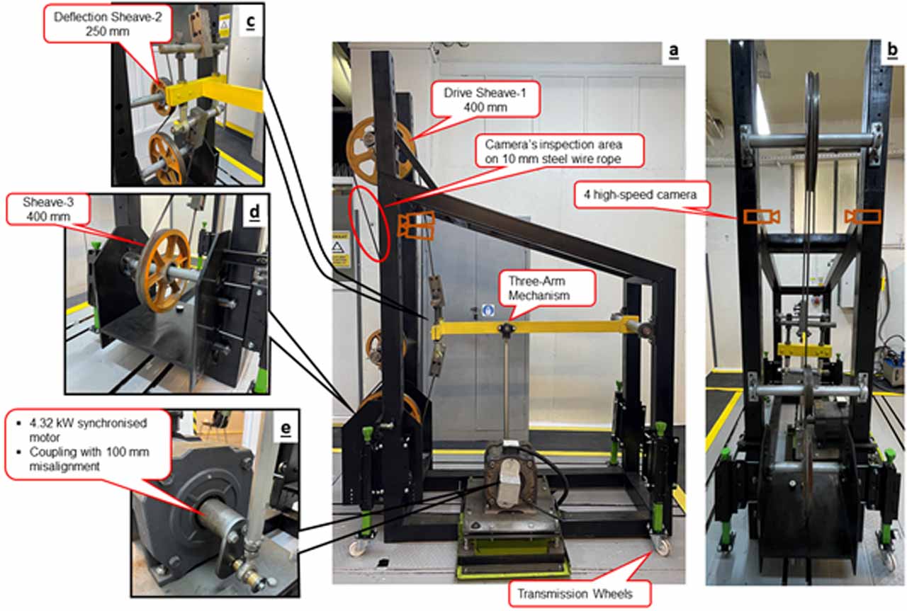
This study aims to determine the fatigue life of steel wire ropes under BoS using image processing and AI simultaneously. The “Rope Fatigue Testing and Analysis Test Setup” located at the Elevator Technologies Laboratory, Faculty of Mechanical Engineering, Istanbul Technical University, is employed for the first time in Türkiye and designed specifically for experimental purposes and assembled with support from the Sanel Asansör company (Figure 1). This research utilizes high-speed cameras and AI for real-time observation, detecting damage that may be missed by the naked eye and allowing for timely interventions.
2. Influencing Factors on Wire Lifetime
Steel wire ropes used in several industrial sectors are subjected to various types of damage depending on their usage. Certain factors influence these damages, which affect the steel wire rope’s lifetime.
2.1 Axial Stress
Axial or normal stresses arise from forces aligned along the rope’s axis. The axial stress is calculated by dividing the tension within the wire rope by its actual metallic cross-sectional area, as depicted in Equation (1). The breaking strength of wire rope is determined by its tensile strength. The formula for axial stress (fa) is:
where:
fa = axial stress (MPa)
T = the tension in the rope (N)
A = actual metallic cross-sectional rope area (mm2)
2.2 Tensile Load
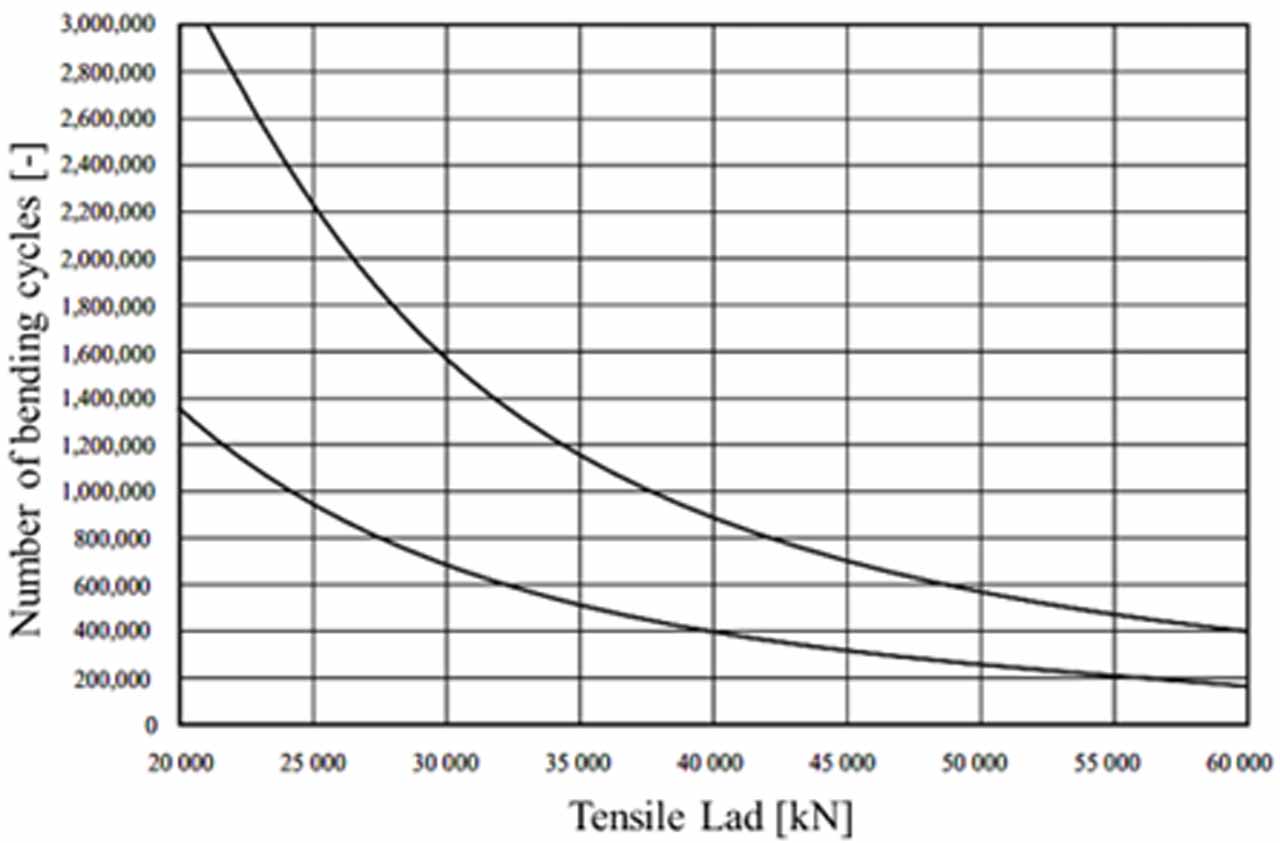
Feyrer[13] has done several experiments on wire rope to relate tensile load to fatigue life. The obtained results show that, by increasing the tensile load (S), the bending lifetime decreases. This can also be concluded from Figure 2.
2.3 Sheave Size
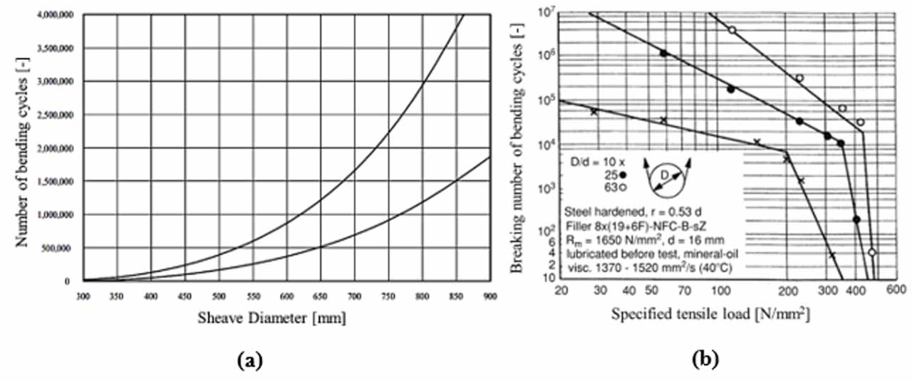
Sheave diameter greatly affects rope strength, causing a loss in effective strength due to bending. Tests show that rope strength efficiency decreases significantly as sheave diameter decreases relative to rope diameter. Manufacturers set sheave size standards based on rope composition.[13] Figure 3(a) shows the relationship between sheave diameter (D) and the number of cycles to discard or complete rupture, indicating that increasing sheave diameter significantly extends rope life. Figure 3(b) demonstrates that, for a 16-mm Filler rope, decreasing the diameter ratio (D/d) reduces the bending lifetime as the specific tensile load (S/d2) varies.
2.4 Bending Principle
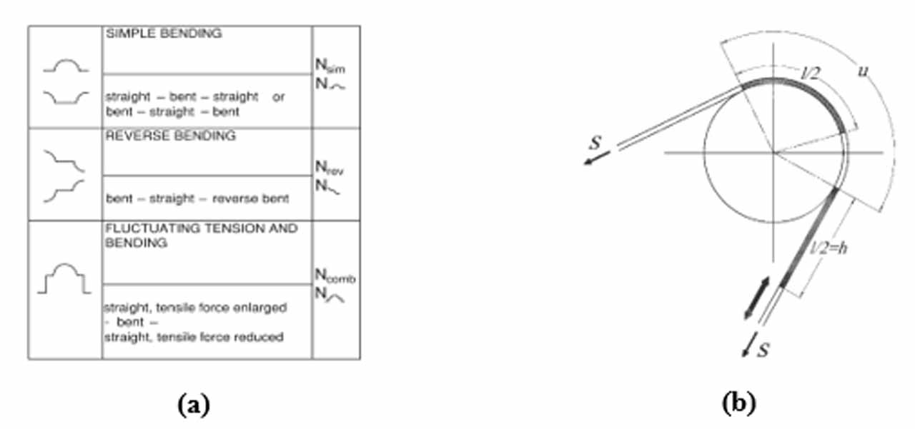
In dynamic working conditions, wire ropes primarily face bending over sheaves, leading to bending fatigue. Understanding the bending mechanism is crucial for realizing bending cycles. Figure 4(a) shows different bending cycles, while Figure 4(b) illustrates the rope stroke (h), the bending length (l) and the contact length (u) between the cable and sheave.
During operation, cables bend either in a simple or reverse shape on the sheaves. In the fatigue test shown in Figure 4(b), the cable undergoes repeated simple bending, with the number of bending cycles denoted as (Nsim). The number of cycles in simple bending depends on the rope’s progression length (h). If h is shorter than u, the cable experiences simple bending each cycle.
The machine designed for this study operates on this principle. During each cycle, the cable bends in both the right and left regions of the test sheave, with a bending length of (h). The number of cycles (Z) and total bending length (l) during the test are calculated using Equation (2).[13] As the rope bends on both sides of the sheave, the total bending length (l) is twice h.
2.5 Shape of the Sheave Groove
The groove shape and material of the sheave significantly impact the lifetime of steel wire ropes. Ideally, grooves should be +6% to +8% of the nominal rope diameter, as tight or wide grooves reduce rope lifespan. Incorrect groove geometry can cause greater reductions in lifespan than predicted by laboratory tests.[14] Proper groove diameter for the rope composition prolongs both sheaves and rope life. Tempered steel grooves prevent changes in groove geometry due to wear, thereby increasing bending fatigue lifetime.[13]
2.6 Rope Composition
Furthermore, the composition of steel wire ropes influences their bending over sheave fatigue life. Ropes are made in various compositions to meet different demands. Coarser compositions with larger wires are suited for abrasion, while flexible compositions with smaller wires are better for frequent bending. Often, a single rope cannot withstand all destructive forces, necessitating compromises in selection. Commonly preferred ropes in lift systems are Seale, Warrington or Filler types with fiber cores and parallel wires of the same pitch. Commonly used steel wire rope constructions are 8×19, 6×19 and 6×25.
2.7 Wire Rope Diameter
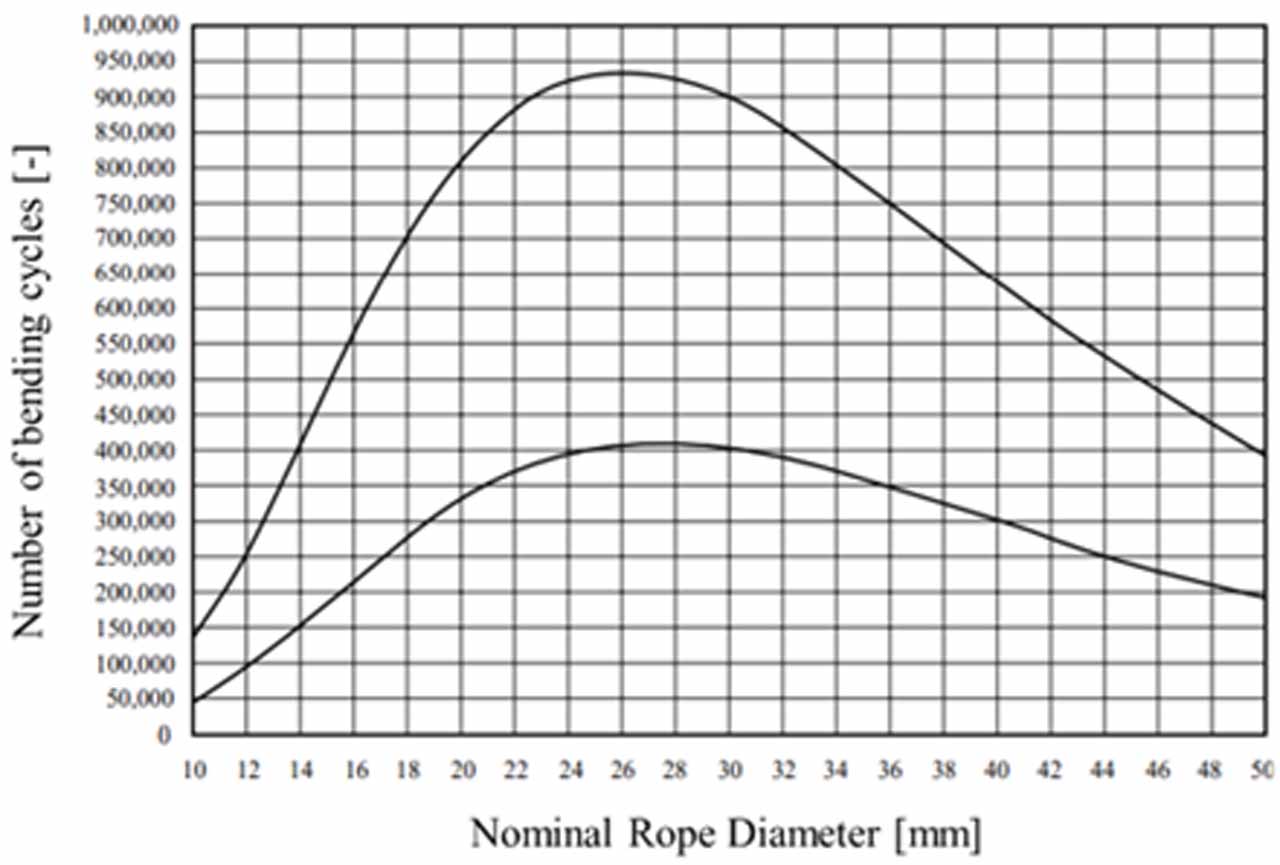
Particularly, wire rope diameter (d) is crucial for fatigue lifetime. Generally, fatigue life increases with the diameter until it reaches the “optimal nominal rope diameter,” after which it decreases. Figure 5 illustrates this experimental finding. Optimal nominal diameter, tensile load and sheave diameter parameters must be considered when selecting wire rope diameter.
2.8 Wire Rope Core
Finally, the core type impacts the fatigue life of wire ropes. Bending tests on ropes with fiber cores showed that sisal and polypropylene (PP) cores had similar results, while polyamide (PA) cores lasted longer due to their superior strength. Increasing the core mass enhances fatigue life. Tests on steel cores indicated that steel cores coated with solid polymer (ESWRC) and those aligned parallel to external strands (PWRC) had longer bending life compared to independent wire rope cores (IWRC).[13]
3. Experimental Procedure
In this section, a description of the test setup design, details of the experiment and the wire rope inspection system are provided.
3.1 Test Setup Specifications
The specially designed test setup, shown in Figure 1, includes sheave-1 with a diameter of 400 mm as the drive sheave, positioned at a height of 2,200 mm from the ground, and a 250-mm sheave-2 as the deflection sheave. Sheave-2 provides necessary pre-tension and maintains the required wrapping angle on the drive sheave. The distance between the drive sheave and the deflection sheave is 1,160 mm. Fatigue occurs in the area moving over the drive sheave with high-speed cameras positioned around the red area of Figure 6 to examine rope damage. The setup uses semi-circular grooved sheaves that can be adjusted vertically to accommodate different diameters, controlling the wrapping angle and contact length between the rope and the sheave. The load mechanism in Figure 6 can hold up to 450 kg to provide the necessary cable tension. The cable drive system uses a three-arm mechanism powered by a 4.32 kW synchronized motor, with an electronic control panel for speed control, ensuring the system operates at the required speed.
3.2 Experiment Samples
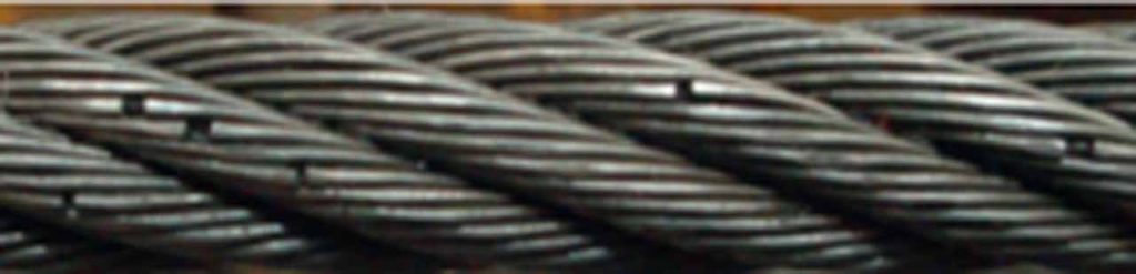
Due to BoS fatigue, steel wire ropes begin to break over time, as shown in Figure 7. This breaking behavior is similar across all steel wire ropes, but the time of occurrence and initiation of fatigue damage varies. Literature on rope fatigue includes studies using different rope types and diameters with sheaves. For instance, Warrington-Seale (IWRC) ropes were used in studies [4, 7]. Both types were used in [3, 5]. Another example is a 109-mm diameter “low-torque, multi-strand” rope in [8, 9]. This project investigates the fatigue life of two rope types, Warrington and Seale, commonly used in the lift industry. Three rope samples of each type, with diameters of 8 mm, 10 mm and 12 mm, are chosen to be tested.
Various discard criteria for wire ropes ensures safe use, varying by system and industry. One key criterion is the number of visible broken wires, based on the rope classification and the number of load-bearing wires in the outer strands. The TS ISO 4309[16] standard presents threshold numbers of broken wires for round-strand steel ropes on steel sheaves. These counts are based on the rope loading condition and operational time as specified in the TS ISO 4301[17] standard.
3.3 Experiment Variables
In previous research studies similar to the planned experiments, different ratios of sheave diameter to rope diameter have been used. These ratios include 10 and 25 D/d ratios in studies by [3, 4], the 25 ratios studied by [2] and [5] and 20 in research by [8, 9]. Additionally, other ratios such as 8, 12, 16, 17, 18 and 23.3 have been used in similar research like [1, 6, 7, 10]. In this project, a sheave diameter of 400 mm will be used as the drive sheave, and three different rope diameters will be considered, which gives ratios of 33, 40 and 50 D/d.
The other parameter to be investigated is the rope’s operating speed because it significantly affects rope life.[3] For this reason, the improved test setup will be operated at speeds of 2,400 rev/s (Hz) and 4,800 rev/s (Hz).
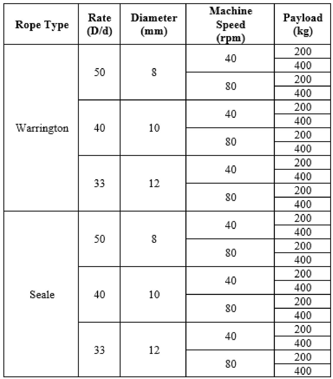
The third and final parameter is the payload to be subjected. During the fatigue test, 200 kg and 400 kg payloads will be applied. After applying these loads, the tension build-up in the rope will be measured and recorded using load cells. During the experiments, ambient temperature and humidity will also be observed and registered. Based on the literature survey, the parameters selected for the experiment can be seen in Table 1.
3.4 AI Embedded Image Processing System
Traditional visual inspection methods for wire ropes are inadequate for many reasons. This paper proposes an alternative approach using high-speed cameras and AI. Four high-speed cameras, each covering a 90° segment of the moving rope, must have at least 2 MP resolution, a 2-mm lens and a frame rate of 249 fps for accurate data capture. These cameras continuously record the rope’s condition, sending footage to a computer with an AI-image processing module. Due to high-speed motion, a powerful graphics card is needed for real-time analysis.
The research aims to detect cracks and determine the discard time of wire ropes. This involves training the AI to classify different types of broken wires, requiring a comprehensive dataset of annotated images. Broken wires identified during experiments enhance the training dataset. The process is time-consuming, depending on the dataset size, but for demonstration, a robust training method was used, taking 4 h for 73 images, which has been augmented to 2,926 images automatically.
Then, the AI-image processing system’s user interface to handle four video inputs from the cameras will be prepared. The generated AI model then analyses the footage, autonomously identifying and classifying anomalies such as cracks or broken wires. The sample of AI-embedded crack detection, which is captured from the software where the AI detected 24 out of 30 cracks with a minimum similarity of 80%, is shown in Figure 8.
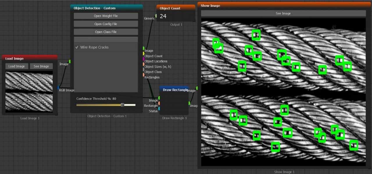
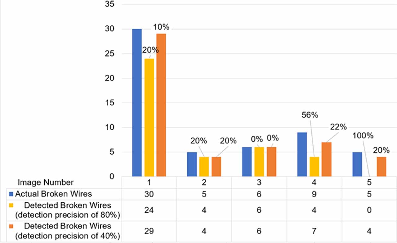
In this AI system, the precision of the detection can be varied from 0 to 100% similarity to the collected dataset. The results of the crack detection process of five different wire rope samples with two detection precisions (80% and 40%) are tabulated for comparison in Table 2. It can be seen that with lower detection precision, the system detects more cracks. Additionally, the error percentages are shown on each bar in the table. This method enhances inspection efficiency and reduces reliance on manual labor and subjective judgment. It allows real-time monitoring, minimizing catastrophic failures and optimizing maintenance schedules. Combining advanced imaging with AI analysis has significant potential for improving industrial maintenance practices and ensuring operational safety.
4. Conclusion
After conducting an in-depth analysis of the experimental data, including observations on the first wire break, discard lifetime and complete failure cycles, an examination of the impact of various experimental variables on these outcomes is warranted. By scrutinizing factors such as wire diameter, rope type, test rate, machine speed and preload, we aim to elucidate their respective influences on the critical performance metrics of wire ropes.
This comparative analysis will shed light on the nuanced interactions between experimental parameters and the resulting mechanical behaviors of the wire ropes. Insights gleaned from these comparisons will not only enhance our understanding of wire rope failure mechanisms but also inform future design considerations and operational practices.
To facilitate clarity and comprehension, graphical representations will accompany the discussion, providing visual insights into the comparative effects of experimental variables on the observed outcomes. Through this multifaceted approach, we endeavor to present a comprehensive and insightful exploration of the experimental findings, paving the way for advancements in wire rope engineering and maintenance practices.
References
[1] D. Battini, L. Solazzi, A. M. Lezzi, F. Clerici, and G. Donzella, “Prediction of steel wire rope fatigue life based on thermal measurements,” International Journal of Mechanical Sciences, vol. 182, p. 105761, Sep. 2020, doi: 10.1016/j.ijmecsci.2020.105761.
[2] Z. Hu, E. Wang, and F. Jia, “Study on bending fatigue failure behaviors of end-fixed wire ropes,” Engineering Failure Analysis, vol. 135, p. 106172, May 2022, doi: 10.1016/j.engfailanal.2022.106172.
[3] Y. A. Onur and C. E. İmrak, “The influence of rotation speed on the bending fatigue lifetime of steel wire ropes,” Proceedings of the Institution of Mechanical Engineers. Part C, Journal of Mechanical Engineering Science, vol. 225, no. 3, pp. 520–525, Aug. 2010, doi: 10.1243/09544062jmes2275.
[4] Y. A. Onur and C. E. İmrak, “Experimental and theoretical investigation of bending over sheave fatigue life of stranded steel wire rope,” Jun. 2012, [Online]. Available: nopr.niscair.res.in/bitstream/123456789/14448/3/IJEMS%2019%283%29%20189-195.pdf
[5] Y. A. Onur and C. E. İmrak, “Experimental determination of degradation influence on bending over sheave fatigue life of steel wire ropes,” Feb. 2013, [Online]. Available: nopr.niscair.res.in/bitstream/123456789/16150/1/IJEMS%2020%281%29%2014-20.pdf
[6] I. M. L. Ridge, C. R. Chaplin, and J. Zheng, “Effect of degradation and impaired quality on wire rope bending over sheave fatigue endurance,” Engineering Failure Analysis, vol. 8, no. 2, pp. 173–187, Apr. 2001, doi: 10.1016/s1350-6307(99)00051-5.
[7] O. Salman and C. E. Imrak, “Experimental investigation of corrosion effect on bending fatigue of the wire ropes,” Indian Journal of Engineering & Materials Sciences, vol. 27, pp. 770–775, 2020.
[8] O. Vennemann, R. Törnqvist, and I. Frazer, “Bending Fatigue Testing of Large Diameter Steel Wire Rope For Subsea Deployment Applications,” The Eighteenth International Offshore and Polar Engineering Conference, Jan. 2008, [Online]. Available: onepetro.org/ISOPEIOPEC/proceedings/ISOPE08/All-ISOPE08/ISOPE-I-08-065/10597
[9] O. Vennemann, R. To¨Rnqvist, B. Ernst, S. Winter, and I. Frazer, “Bending Fatigue Tests Using a Suitable NDT Method to Determine Lifetime of Large Diameter Wire Ropes for Offshore Lifting Applications,” Jan. 2008, doi: 10.1115/omae2008-57128.
[10] D. Zhang et al., “Bending fatigue behaviour of bearing ropes working around pulleys of different materials,” Engineering Failure Analysis, vol. 33, pp. 37–47, Oct. 2013, doi: 10.1016/j.engfailanal.2013.04.018.
[11] X. Huang, Z. Liu, X. Zhang, J. Kang, M. Zhang, and Y. Guo, “Surface damage detection for steel wire ropes using deep learning and computer vision techniques,” Measurement, vol. 161, p. 107843, Sep. 2020, doi: 10.1016/j.measurement.2020.107843.
[12] K. Minagawa and S. Fujita, “Application of Image Processing to Health Monitoring for Wire Rope of Lift systems,” Transportation Systems in Buildings, vol. 2, no. 1, Nov. 2018, doi: 10.14234/tsib.v2i1.143.
[13] K. Feyrer, Wire ropes: Tension, endurance, reliability. Springer Berlin Heidelberg, 2015. doi: 10.1007/978-3-642-54996-0.
[14] D. -Ing., R. Verreet, “Calculating the service life of running steel wire ropes,” 1998. Available: ropetechnology.com/downloads/brochures/bro_calculating-the-service-life-of-running-steel-wire-ropes.pdf
[15] E. Gorbatov et al., “Steel rope with longer service life and improved quality,” Metallurgist, vol. 51, 2007, doi: 10.1007/s11015-007-0052-y.
[16] TS ISO 4309, “TS ISO 4309 Cranes-Wire ropes-Care and maintenance, inspection and discard,” 2017. [Online]. Available: iso.org
[17] TS ISO 4301, “TS ISO 4301-Cranes and lifting appliances – classification – Part 1 : General,” 2016. [Online]. Available: standards.iteh.ai/catalog/standards/sist/9512d298-4f37-45bf-b96a-
Get more of Elevator World. Sign up for our free e-newsletter.
![]()


![]()