Computer-Aided Structural Analysis of the Lift Car-Frame System Under Emergency Arrest Operational Conditions
Jan 1, 2022

Your authors describe CAA model regarding cab-stress predictions.
by Mohammad Ghaleeh, Stefan Kaczmarczyk, Shafqat Rasool, Jonathan Adams and Nawar Al-Esawi
![]() This article was first presented by the Online Symposium on Lift and Escalator Technologies, September 23-25, 2020, by the University of Northampton, U.K.; for more information, visit liftsymposium.org.
This article was first presented by the Online Symposium on Lift and Escalator Technologies, September 23-25, 2020, by the University of Northampton, U.K.; for more information, visit liftsymposium.org.
Keywords: Car, Frame, Buffering, Dynamics, Bending, Deflections, Permissible Stress
Abstract. The paper presents Computer-Aided Analysis (CAA) model of a lift car-frame system. Structural analysis is carried out by the application of the Finite Element Method (FEM) to predict the responses and stresses arising in the system under the emergency conditions. The emergency scenario presented in the paper involves a buffer strike event that occurs during the car overtravel. The model can then be used to optimize the design to ensure safe operation of the system.
Introduction
Vertical transportation systems (VTS) such as lifts (elevators) are key elements in the built environment, especially in the high-rise building environment. It is extremely important that the design of VTS provide efficient and safe service to building occupants and users.[1]
The dynamic loads act upon components of the lift system during normal operation and emergency conditions. High levels of dynamic stresses in the lift car-frame structure might then occur. To satisfy the requirements of safety standards and to meet the criteria for acceptable service, thorough understanding of engineering principles and models applied is of paramount importance in conducting the system calculations.[2]
The aim of this work is to demonstrate a computer-aided solution and analysis of the dynamic responses that arise during an emergency scenario. The emergency arrest is initiated when the car overtravels the designated terminal floor at the bottom of the hoistway. The dynamic loads that arise during the event are determined and applied in FEM structural analysis of the car frame structural components.
Car Overtravel and Emergency Arrest
The overtravel arrest mechanism consists of buffers beneath the car (and often beneath the counterweight).[2] Three types of buffer are permitted by safety codes[3]: linear, energy accumulation type buffers; non-linear, energy accumulation buffers; and energy dissipation buffers. Consider a scenario when the car is striking an energy dissipation buffer (Figure 1).

The equation of motion describing the dynamics of the system when the car traveling at speed V has engaged an energy dissipation buffer (buffering event) is given as

where g is the acceleration of gravity, x is the displacement, M is the mass of the car-frame assembly, c represents the coefficient of damping and k denotes the coefficient of stiffness of the buffer. The buffer acting at the buffer striking plate is determined as

In this model of the car-frame, buffer dynamics is represented by the fundamental mode with the car-frame treated as a rigid body. By solving the equation of motion (1) the buffer force can then be readily evaluated from equation (2).
Structural Analysis of the Car-Frame Assembly
To determine the dynamic deformations and stress levels of the car-frame assembly, the system can be analyzed by the application of Finite Element Method (FEM). The behavior of the structure is then represented by the following equation[4]

where [M] is the mass matrix, [C] is the damping matrix, [K] is the stiffness matrix, ![]() is the load vector and
is the load vector and ![]() denotes the displacement vector.
denotes the displacement vector.
CAD Model
The lift car-frame assembly is a combination of three distinct components: car bodywork (enclosure), sling (frame) and car platform. A CAD model used in the study is shown in Figure 2.

Fundamental Mode Analysis of the Car-Frame Buffer System
Equation (1) can be re-formulated in terms of the fundamental mode parameters as

where ![]() is the damping ratio and
is the damping ratio and ![]() represents the fundamental frequency of the car-frame buffer system.
represents the fundamental frequency of the car-frame buffer system.
Equation (4) is then solved considering the car speed of 2 m/s, the damping ratio z = 0.25, 0.75, and the fundamental frequency assumed as 1.63 Hz, respectively. The results are shown in Fig. 3.
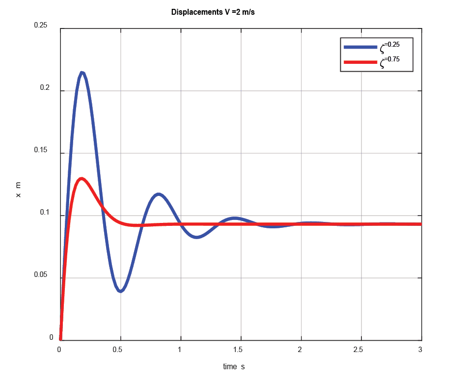
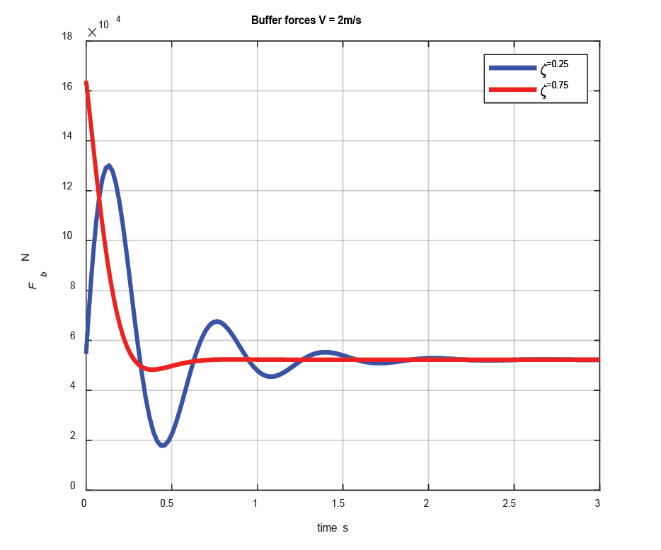
The dynamic deflections are shown in Figure 3 (a) and the buffer forces are illustrated in Figure 3 (b), respectively.
The rating of buffers is based on arresting the car from 115% rated speed (the overspeed governor electrical trip speed). Safety codes[4] stipulate that the total possible stroke of energy dissipation buffers shall be at least equal to the gravity stopping. Considering that the car strikes the buffer at rated speed and the gravity stopping distance, for the rated speed of V = 2 m/s, is calculated as ![]() = 0.2696 m, it is evident that the maximum deflections of the buffer are smaller than the minimum buffer stroke.
= 0.2696 m, it is evident that the maximum deflections of the buffer are smaller than the minimum buffer stroke.
FEM Simulation and Results
In the FEM simulation of the car-frame assembly, the buffer channel beam structure is selected. The bending stresses (Figure 4) and the deflection levels (Figure 5) are determined under the maximum load conditions as illustrated in Figure 3 (b).
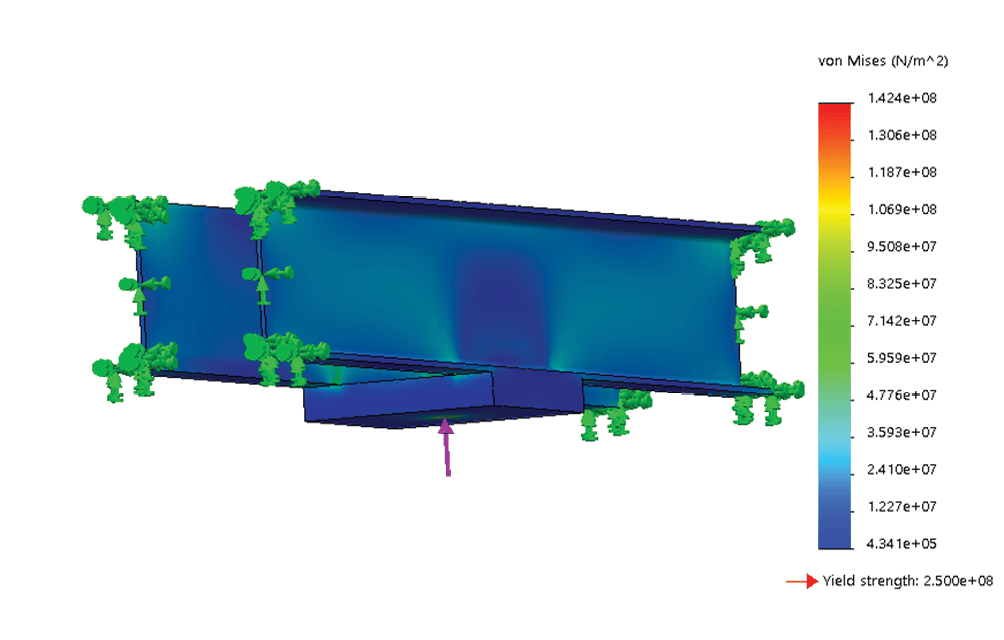
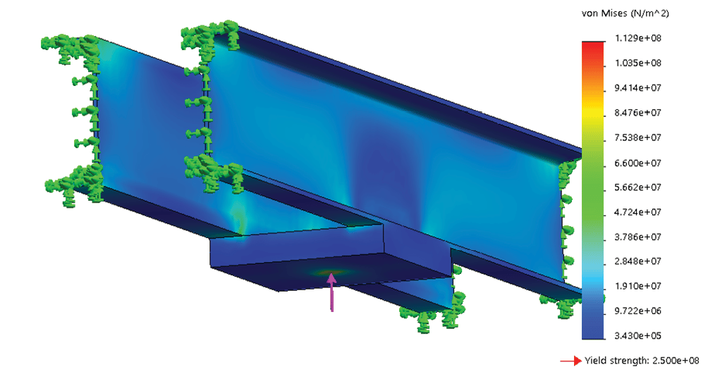
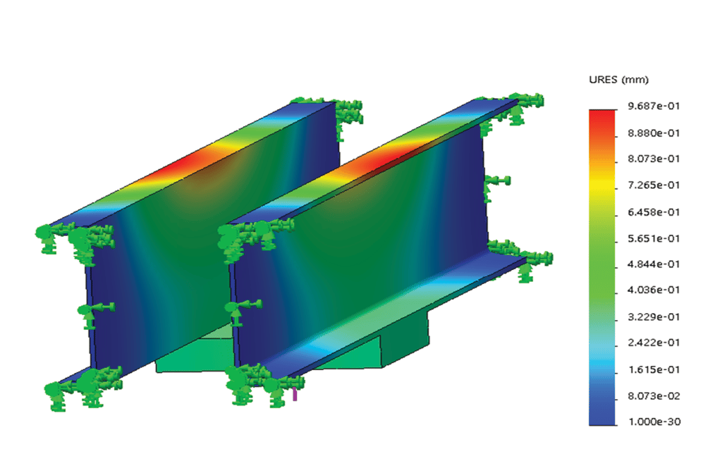
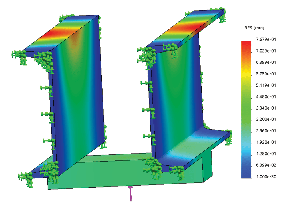
Maximum permissible stresses in car-frame buffer plank under buffering conditions specified in ASME A17.1 are given as 189.6 MPa (27,500 psi). It is evident that under the loading conditions considered, the maximum stress levels (determined as 142.4 MPa and 112.9 MPa, respectively) do not exceed the permissible value. Normal practice for dealing with loads that act at the buffer channel beam (safety plank) structure is to ensure that the deflections shall be no more than ![]() th of the channels’ span. Considering the span length of 2350.7 mm, the maximum deflections (determined as 0.9687 mm and 0.7679 mm, respectively) are within the acceptable range.
th of the channels’ span. Considering the span length of 2350.7 mm, the maximum deflections (determined as 0.9687 mm and 0.7679 mm, respectively) are within the acceptable range.
Conclusions
The analysis and results presented in this paper demonstrate that large deformations and stress levels may occur in a lift system during an emergency arrest event triggered by the car overtravel. The stress and deflection in the buffer channels need to be assessed in the worst case of operation. This might be during buffering events, as demonstrated in the paper.
References
[1] S. Mirhadizadeh, S. Kaczmarczyk, N. Tongue, H. Al-Jelawy, P. Feldhusen, W Delk, K. Anderson, F. Dudde, “Modelling and Computer Simulation of aerodynamic Interactions in High-Rise Lift Systems.” Proceedings of the 5th Symposium on Lift and Escalator Technologies. Volume 5, September 2015, Northampton, UK, pp. 117–123.
[2] J.P. Andrew and S. Kaczmarczyk, Systems Engineering of Elevators. Elevator World, Mobile, AL (2011).
[3] British Standards Institution, Safety rules for the construction and installation of lifts — Lifts for the transport of persons and goods Part 20: Passenger and goods passenger lifts. BS EN 81-20:2014.
[4] S.S Rao, Mechanical Vibration. Prentice Hall, Singapore (2005)
Editor’s note: The authors are members of the Faculty of Arts, Science and Technology (FAST), University of Northampton, University Drive, Northampton NN1 5PH, U.K.
Get more of Elevator World. Sign up for our free e-newsletter.


