Early Electric Elevator Controllers, Part One
Feb 1, 2015

The first of a two-article series on Cutler-Hammer’s 1913 catalog bulletins that offer a unique glimpse into the world of early electric elevator controllers
The inventors of the electric elevator faced one of the fundamental problems earlier inventors had faced in their design of steam- and hydraulic-powered systems: how to control the engine or motor that drove the elevator machine. An effective means of control needed to ensure a smooth start, a steady (and rapid) acceleration to the elevator’s optimum operating speed, and an equally smooth deceleration and stop at the end of the run.
In the beginning, almost all manufacturers of electric elevators built specific controllers for their unique machines; however, advancements in electric motors eventually restricted much of the R&D in controller design to larger elevator companies or to firms that specialized in electric-motor components and accessories. The latter group included Cutler-Hammer Manufacturing Co. of Milwaukee, which became a leader in the development of electric elevator controllers in the early 20th century. These controllers became standard features of machines manufactured by numerous regional elevator companies. In 1913, Cutler-Hammer produced an extensive catalog of its products — divided into individual bulletins — that provides a unique glimpse into the world of early electric elevator controllers.
The 1913 catalog featured 25 bulletins on controllers for DC motors, 15 bulletins on controllers for AC motors and 29 bulletins on accessories for electric elevator systems. The bulletin sets for DC and AC controllers featured indices that described the critical features of each controller type. Bulletin 7099, “Index and General Description: Direct Current Elevator Controllers,” also included a brief rationale for the use of electric elevators, which serves as a reminder that, at this time, hydraulic elevators dominated the market, and the relatively new electric elevator was still an up-and-coming rival. Cutler-Hammer promoted the use of electric elevators (and their controllers) by highlighting the advantages of electric motors:
“The development of electric motors suited to the work of operating passenger and freight elevators, and of systems of control also designed with special reference to these classes of service, make it possible to employ the motor drive today with all types of elevators and to secure results fully equal to the best results by any other system of operation. The motor drive possesses a number of inherent advantages, among which are low first cost, economy of maintenance, simplicity of equipment and operation, compactness, and great flexibility of control. Add to these the fact that, owing to the possibility of installing safety devices at all points, the motor drive is incomparably the safest system, and it is not difficult to understand why electric elevators are generally preferred to all others.”
However, a manufacturer’s ability to employ electric motors “with all types of elevators” did not mean the application of an electric motor to elevator service was a simple task.
The complexity of this task was outlined by Cutler-Hammer in a section titled “Information We Should Have,” which referred to information that should accompany orders for controllers. The section consisted of a list of 21 questions, divided into two sections that addressed the elevator and motor separately (Table 1). Potential customers were asked to “answer as many questions as possible” to aid in the selection of the controller best suited to their need
Cutler-Hammer also provided detailed information on electric-motor specifications, which was keyed to the bulletin numbers of specific controllers (Figure 1). An additional tool provided to customers was a “Ready Reference Chart” that was designed “for determining the power required in any elevator installation” (Figure 2). The chart, which assumed an overall system efficiency of 50%, was accompanied by the following instructions: “To determine the proper size motor to use in any case, follow the diagonal line corresponding to the unbalanced load up to the point where it crosses the vertical line corresponding to the speed desired.”
Bulletin 7099 concluded with three “Tables of Useful Information” that provided data (based on the power supplied) on the horsepower rating of the motor; full current load; fuse size in mainline circuit; and copper-wire sizes in the mainline, armature, series field, shunt field (shunt brake) and control circuit (Figure 3).
In 1913, Cutler-Hammer manufactured 24 different controllers for DC motors, which were divided into four categories: full-magnet controllers (for slow-, moderate- and high-speed passenger elevators and slow- and moderate-speed freight elevators), semi-magnetic controllers (for slow-speed passenger or freight elevators), semi-magnetic controllers (for belt-driven freight or sidewalk elevators) and push-button controllers (for passenger elevators and dumbwaiters). Within each category, controller types were differentiated by speed; starter type; and optional features, such as dynamic brake systems and reverse switches. Bulletin 7110, “Direct Current Reversible Two Speed Full Magnet Controllers for High Speed Passenger Elevators,” was the longest bulletin in this set (12 pages) and included a thorough overall description of DC controllers and their related options and accessories. The bulletin’s cover featured an illustration of the controller and a detailed price list. It included a line drawing of the controller’s front and side elevations that included approximate dimensions (Figures 4 and 5). The controller consisted of an “iron-angle frame,” which supported a series of dull-black slate panels that carried the requisite solenoid switches, fuses, etc. The controller was designed:
- “To disconnect in the off position both sides of the line from the armature, series field, resistance and brake magnet
- To accelerate the motor automatically by cutting out the armature starting resistance step by step, and also the series field with the last step of armature resistance (this by means of individual series relay control), giving smooth acceleration under all load conditions
- To control the speed of the elevator by cutting resistance in or out of the shunt-field circuit of the motor, affording positive speed control under widely varying loads
- To bring the elevator quickly, but smoothly, from high to low speeds, regardless of load, making accurate stops at landings an easy matter
- To open the circuit to the motor should an overload current flow
- To apply the dynamic brake in the off position
- To operate the elevator at normal speed from the switchboard for test purposes
- To open the shunt-field circuit in the off position of the controller”
Not surprisingly, Cutler-Hammer stated that safety was its “primary consideration.” The company claimed its controllers were designed such that the “instant” a problem occurred “in the elevator mechanism, the motor or the controller,” the latter would “disconnect the motor from the line, apply the brake and bring the car safely and smoothly to rest.”
A common problem associated with electric-motor use in the early 20th century was current overload due to fluctuations in the power supply. While circuit breakers were employed to ensure motors were not damaged, a tripped breaker on an elevator motor and the associated time required to reset the breaker meant an elevator could be out of service for a prolonged time. Cutler-Hammer’s solution to this potential problem was to link the “circuit-breaker relay. . . with the car switch in such a way that, should the motor be stopped by the action of the circuit-breaker relay, the relay can be reset from the car by merely moving the lever of the car switch to the off position.”
The operator’s ability to quickly reset the breaker ensured there was a minimal disruption in service, and, according to Cutler-Hammer, ensured “the maximum of protection, since it is possible to keep this relay set very close to the safe maximum load of the motor.” This feature was also seen as eliminating a problem associated with manually operated circuit breakers, which required “the operator to leave his car. . . or to signal the engineer to reset the breaker.” The delay in service and inconvenience in resetting the breaker was perceived as a “sufficient annoyance” to tempt the operator or engineer to “readjust the circuit-breaker relay so that it will not trip so easily.” This statement is of interest, because it implies the operator played a role in the operation of the elevator beyond simply “driving” the car.
The responsibilities of the operator were also a factor in another controller feature. The 7110 controller was designed to provide three operating speeds: “slow down,” “normal” and “high” speeds. The first was designed to facilitate more-accurate landings. In 1913, only push-button elevators used in residential settings (homes or small apartment buildings) employed automatic floor-leveling devices. In most buildings, the operator manually leveled the elevator car with the landing, which was characterized by Cutler-Hammer as an activity requiring considerable skill:
“Even with the older forms of two-speed, full magnet, elevator controllers the normal speed of the car is fairly high, often attaining 150 fpm, and the coasting when attempting to stop from this speed is considerable, in spite of the retarding influence of the mechanical and dynamic brakes. To make an accurate landing under these conditions requires careful calculation on the part of the operator. If he throws the lever of the car switch to the off position an instant too soon or too late, the car misses the landing, and it then becomes necessary to inch it up or down, involving a loss of both time and energy.”
Cutler-Hammer’s solution to this problem was its “slow down” speed, which was equal to approximately 30% of the “normal” operating speed. At this slower speed, it was perceived to be “very easy to make an accurate landing,” with “the tendency of the car to coast. . . practically eliminated.” The “slow down” speed was also used in conjunction with the “mechanical brake and. . . limit switches so that the car will be brought to a full stop at the last landing, instead of coasting past the limits. . . and hitting the bumpers at the top or bottom of the hatchway.” Part Two of this article will conclude the examination of Cutler-Hammer’s 1913 elevator controllers. The conclusion will address additional controller features, car equipment, the role of the operator and the application of these controllers to elevator machines built by various regional companies.
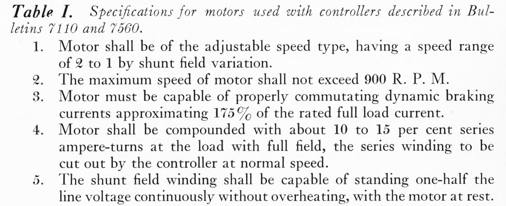
Figure 1: “Motor Specifications,” Cutler-Hammer Bulletin 7099, “Index and General Description: Direct Current Elevator Controller” 
Figure 2: “Ready Reference Chart,” Cutler-Hammer Bulletin 7099, “Index and General Description: Direct Current Elevator Controller” 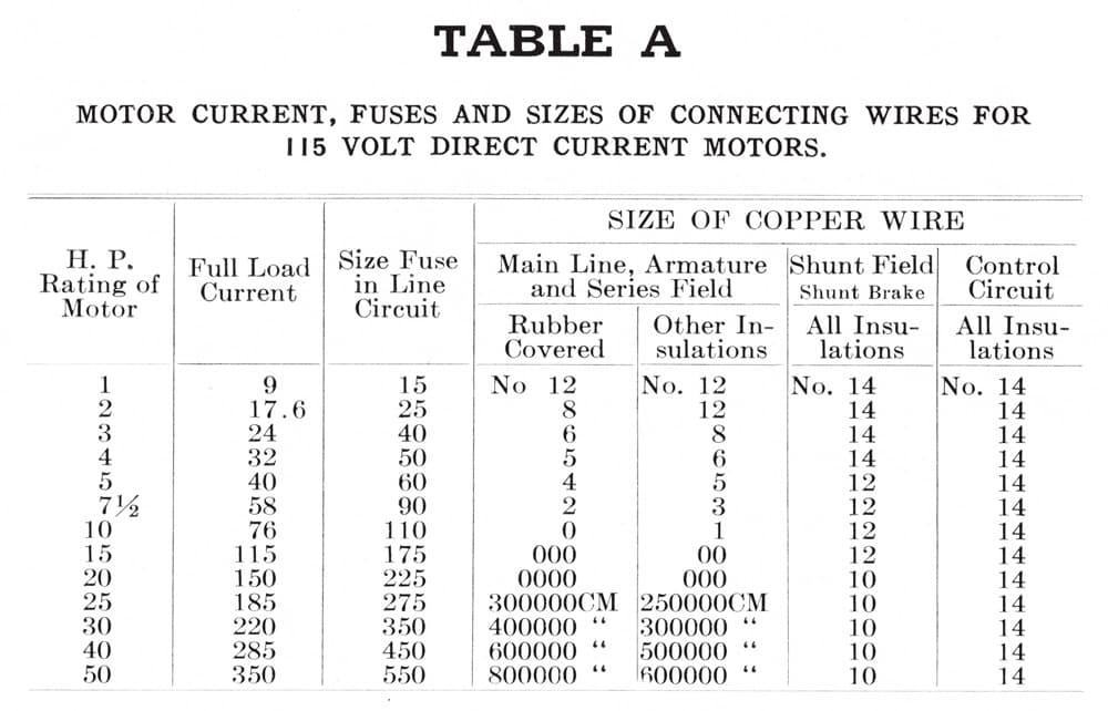
Figure 3: The first of three “Tables of Useful Information,” Cutler-Hammer Bulletin 7099, “Index and General Description: Direct Current Elevator Controller” 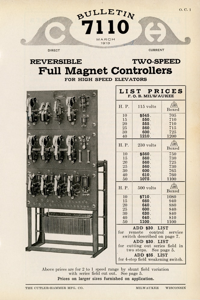
Figure 4: Cover, Bulletin 7110, “Direct Current Reversible Two-Speed Full Magnet Controllers for High Speed [Passenger] Elevators” 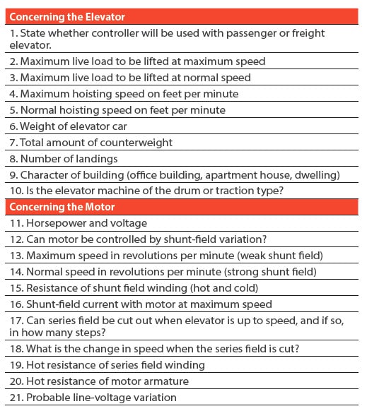
Table 1: Cutler-Hammer’s “Information We Should Have” section

Get more of Elevator World. Sign up for our free e-newsletter.