Elevator Drive Maintenance
Oct 1, 2018

How to extend the life of VFDs, including an overview of maintenance inspection points and procedures
Everyone in the elevator industry knows how complex an elevator system is. There are many moving mechanical parts, as well as electronic power-transmission components. Obviously, maintenance is required to maximize the lifespan of the elevator machine and minimize the possibility of failure during service. At the heart of the elevator control system is the inverter, or variable-frequency drive (VFD). A VFD provides power and control to the elevator hoist motor, yet it is a maintenance item that may be overlooked. This article will provide some tips for VFD maintenance. First, however, a word of caution: When performing maintenance on a drive, make sure power has been removed and that the drive’s DC bus capacitors have fully discharged. Failure to do so may result in injury or death.
The environment in which the drive is placed needs to be considered. Ambient temperature, power quality, airborne contamination and even altitude will all have an impact on the drive’s internal components. Most drive manufacturers will specify the operational limits of these variables — always follow the manufacturer’s recommendations.
Heat is the enemy, and it can damage sensitive electronic components. Over time, heat can cause almost any VFD’s internal components to fail if action is not taken to mitigate its effects. During normal operation, the VFD is required to provide high peak currents to generate enough torque to accelerate the car up to speed and to control the deceleration, leveling and stopping. This means a considerable amount of heat will be created by its output transistors, which are insulated-gate bipolar transistors (IGBTs). The drive’s other power-stage components, like input rectifiers, also create heat.
The drive’s cooling system is crucial; without it, the power-stage components would go into thermal overload and fail. The typical VFD cooling system is composed of fans and a heatsink designed to disperse the heat. But, it is also important that the control cabinet, where the VFD is housed, is well ventilated. High ambient temperatures will compound the stress to drive components, so, if possible, the machine-room temperature should be regulated.
One drawback of the VFD’s cooling fans is that they pull in airborne contaminants. In time, the contaminants build up and can contribute to failure. The first step to reducing contamination buildup in the VFD is to keep the control cabinet closed as often as possible. Keep the VFD’s fans free of contamination buildup to prevent clogging by periodically checking and cleaning them. This is particularly important in environments where excessive amounts of dust are generated (i.e., drywall dust during construction). The heat sink should also be cleaned if it has accumulated a lot of dust to allow for better heat dissipation. Compressed air can be used to safely blow out the fans and heat sink. It would also be a good idea to remove the drive housing to inspect the interior for excessive contamination and blow it out if necessary. If the drive is triggering overheat errors, it is likely that one or more of the cooling fans has failed and needs replacement.
Conductive contaminants, such as carbon dust created by the friction between the ropes and sheave, are detrimental to a VFD. Over time, if enough carbon dust builds up in the VFD, a short- circuit condition could be created. Again, keep the control cabinet closed as much as possible. Periodically inspect the VFD and clean it out as necessary. Rewiring and drilling in the control cabinet can also introduce conductive contaminants into the VFD. In scenarios like this, it is very important that the VFD is covered so that nothing can fall into its interior.
When maintenance is performed on the elevator system, it is often necessary to turn power off to the control cabinet. Whenever power is cycled back on, the VFD’s input is subjected to high inrush current as the DC bus capacitors begin to charge up. The VFD utilizes a charge resistor, connected between its input and intermediate circuits, to limit the inrush current during power up. Care should be taken not to cycle power too frequently, as this can lead to damage to the VFD’s charge resistor. Drive manufacturer KEB recommends waiting a minimum of 2 min. between power cycles.
Spare VFDs may be kept on hand in case of failure in critical locations such as hospitals. In such cases, the spare units could be sitting on a shelf for an extended time. When the drive’s electrolytic DC bus capacitors sit deenergized for a long period of time, the oxide film formed inside the capacitors deteriorates. When full power is finally applied to the drive, this oxide film builds up too rapidly, producing internal pressure from heat and gas, which can destroy the capacitors.
To avoid this, the inverter’s DC bus capacitors need to be “reformed.” Reforming is a simple process and should be performed if the drive is going to sit for over one year without being powered. After one to two years, just power the unit up with full voltage, and let it sit idle for 1 hr. without modulation; do not run the drive. If it sits for more than two years, the process is a little more involved. A variable power supply will be required so the applied incoming voltage can be ramped up in smaller increments. Start powering up at 50 V and let the capacitors charge in 15-min. intervals, raising the voltage by another 50 V at each interval until full voltage is applied. Then, let the drive sit powered up at full voltage for 2 hr. Again, do not run the drive. Add one hour of charging time for each additional year the drive has been sitting.
Sometimes, the maintenance of other system components will directly affect the VFD. For example, check all wiring at terminal connections, including ground connections. Over time, these connections can become loose due to vibration. Loose wire connections can result in voltage or current spikes reflected at the drive, resulting in component failure. Sometimes, arc damage on the terminals will be visible, indicating a loose connection. It is recommended to check all connections for tightness from time to time. Also note the condition of the wire insulation. Stiff, brittle or discolored wire insulation can indicate sustained, excessive current draw. If this is noticed, its cause should be investigated.
Inspect the motor contactor: the internal contacts wear down due to arcing that occurs with normal usage. Often, a worn or damaged contactor will result in overcurrent errors on the VFD and even damage to its IGBTs.
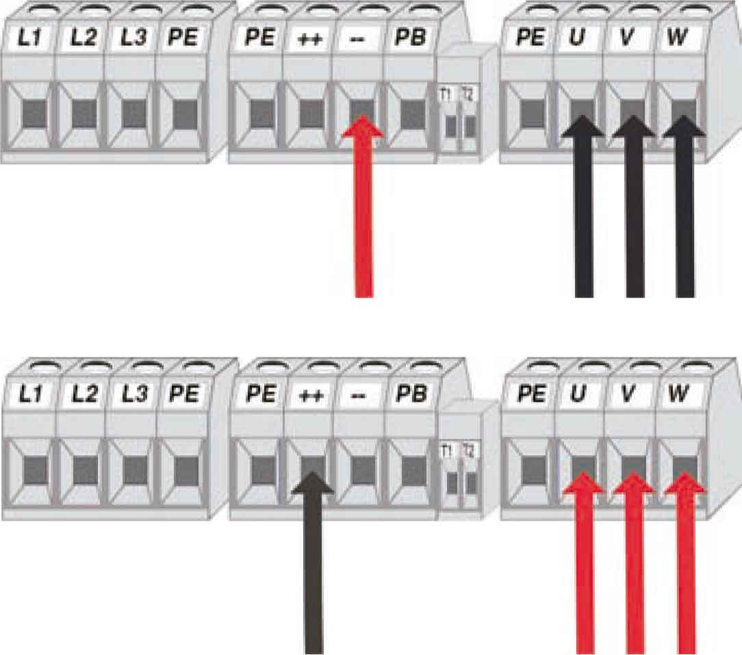
Pay attention to error codes displayed on the drive and try to determine the cause of the errors. Overcurrent and overvoltage errors can be caused by loose connections, a bad contactor or a bad motor. But, they can also be caused by internal drive issues. A diode check can be done to check for shorts or opens if it is suspected that one of the VFD’s power-stage components (like the IGBTs, braking transistor or input rectifiers) have failed. This is a test that can be performed using a multimeter with diode checking functionality. The diode test measures the voltage drops across the diodes of the components. Be sure the drive is powered down and allow the DC bus to discharge. Remove the wiring from the specific drive terminals to be tested. The measurements are taken with respect to the positive and negative sides of the DC bus. There should be a small voltage drop across each component, measuring in the tenths of a volt (approximately 0.3 VDC). If the meter reads “0 V” or “OL/open,” then it is very likely the component has failed.
It should be noted that the test does not always indicate a failure; there are cases (depending on the physical condition of the component after failure) in which the measured voltage drops will be normal, even though one of the power-stage components has failed. At this point, if it is unclear through troubleshooting whether a failure has occurred, a repair evaluation would be necessary.
There are many system components that can fail at any time. Although it may not be possible to prevent every failure, vigilant inspection and proactive measures will most certainly reduce the number and frequency of them. The reliability and service life of an elevator system is only as good as the maintenance plan that is implemented. The cost to repair or replace a VFD can be expensive. A thorough maintenance plan that includes the VFD can help delay that eventual cost significantly.
Get more of Elevator World. Sign up for our free e-newsletter.


