Finite Element Analysis of Fixed Bolts Used in Escalator Motors
Jan 1, 2012

This report analyzes the connective strength and displacement of split and integral bolts.
by Yu Zetao and Feng Kai
Abstract
According to the joint forms between the head and studs, fixed bolts used in escalator motors can be divided into two forms – split and integral. Using finite element analysis software ANSYS Workbench, this paper analyzes the connective strength and displacement of these two kinds of bolts to provide a reference for the selection of fixed bolts on the escalator motor. The results show that the bearing capacity of the integral bolts is 1.8 times higher than those that are split.
Introduction
The power and braking of an escalator is transmitted by the motor through the drive chain to the step system. To ensure the chain wheel sprocket and drive chain mesh properly and reliably, the drive chain should have certain tension degrees. If the displacement of the motor led to the change of the original tension degrees, escalators would reverse and serious accidents would occur, such as passengers falling or stepping on each other. Therefore, the well-fixed escalator motor is extremely important for the operational safety of the entire unit.
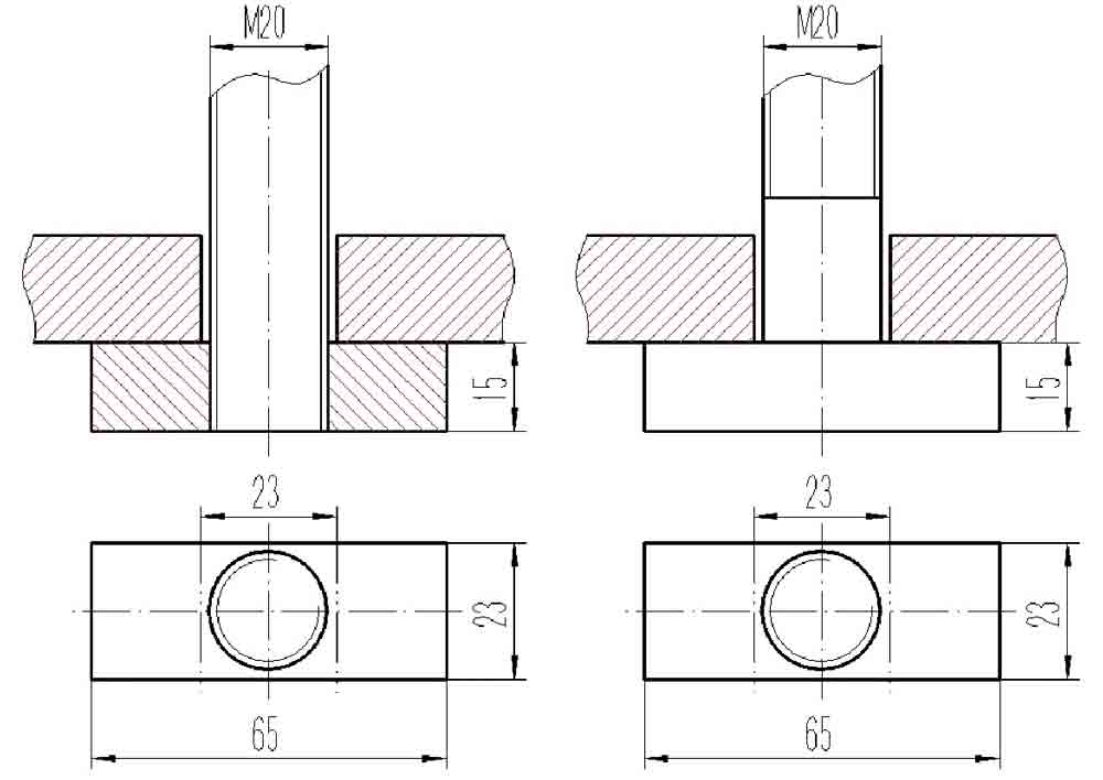
Connection types between the base of a drive motor and its frame can be divided into reaming-hole and through-hole connections. The through-hole connection can be divided into two forms – split and integral, according to the joint between the head and studs of the bolt (Figure 1). Currently, there are many detailed force analyses on the connections between bolts and double angle,[1] double channel[2] and flange.[1] However, a study on the force and strength analysis of these two kinds of bolts, as well as comparison research, has not yet been performed.
The connective function of these two kinds of bolts has no difference, but, because of the different internal structures, the connection strengths are different. This article examines one type of fixed bolt as the research object and establishes two kinds of entity unit models. Workbench then analyzes and compares the connection strength results based on the actual situation of the forces and constraints. This provides the reference for the selection of the fixed bolts on the escalator motor.
ANSYS Workbench Analysis The Split Bolt Model
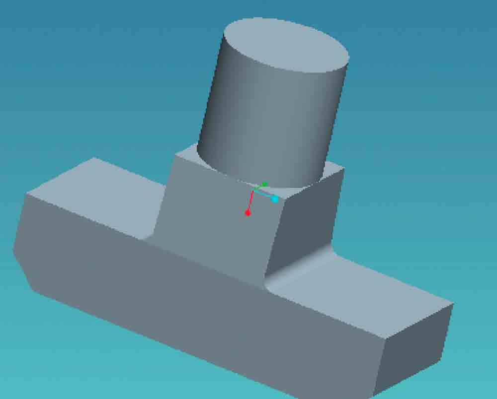
The model of the contact surface between the head and the studs of an M20 bolt is complex. To obtain accurate stress data and precisely reflect their interaction, we must establish the actual size of the 3D entity model for the studs and head of bolts with the Pro/Engineer 3D CAD program’s modeling function. After assembling, we get the model of a split bolt in Pro/Engineer (Figure 2).
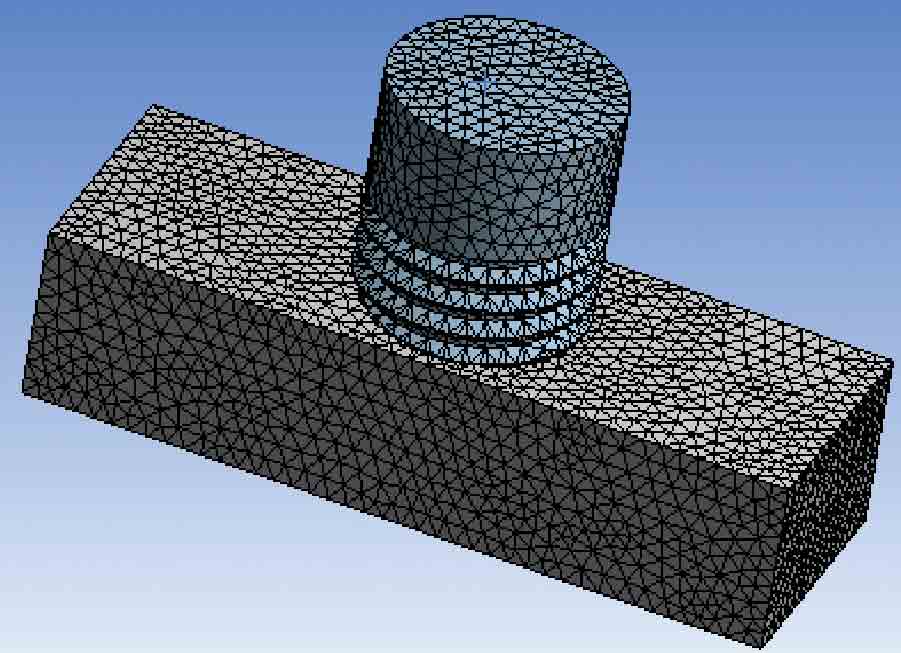
Next, we import the model into Workbench to perform a finite element analysis. To avoid direction and mesh size sensitivity,[3] we define all entities as solid45 units, which is an eight-node hexahedral-structure entity unit. The property of material is shown in Table 1.[4] We choose an automatic approach to mesh, while keeping the element midsize node[5] and setting the element size at 1.6 mm. After meshing, the finite element model is complete, with the number of the model’s nodal points being 110,223 and units at 72,744 (Figure 3).
To ensure the model can simulate the actual contact state when the whorls interact, we define the whorls’ surface interface. The type of contact is frictional, and the factor is 0.15. The formulation is pure penalty.
The Integral Bolt Model
The process of building an integral bolt model is similar to that of the split. First, build the bolt model in Pro/Engineer (Figure 4), then transfer the model into Workbench. The difference is that there is no assembling process for the whorl and interface definition process. We also define all entities with solid45 units. The material property is shown in Table 1. We choose an automatic approach to mesh while keeping the element midsize node and setting the element size at 1.6 mm. After meshing, the finite element model is complete, with the number of the model’s nodal points being 49,817 and the units 30,434 (Figure 5).
Load and Restriction
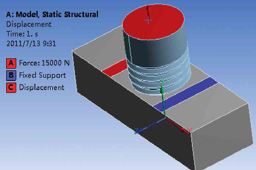
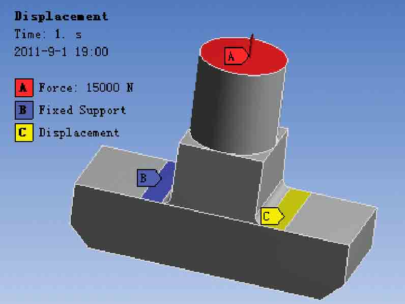
The maximum force of each bolt is about 15,000 N at the fully loaded working condition when the escalator goes up. In this article, the 15,000 N forces loads on an area, which is 35 mm from the bottom of the bolt; its direction is axial.
Only the bottom of the studs makes contact with the edge of the groove in the actual operation process when pressing the head of the bolt. To simplify the calculation, we insert “compression only support” between the head of the bolt and the T-form groove on the fixed board of the escalator motor, then read the range of contact pressure serving as the restriction range. Its length is 5 mm and the width is 23 mm (the same as the head). Then, we cut two separate 5 mm x 23 mm regions on the surface of the head of the bolt as loading restrictions. One is inserted as fixed support, and the other as displacement, with its Y component free and X and Z components at zero. The loads and the restrictions of the split and the integral bolts are shown in Figure 6.
| Structural Steel | |
| Young’s modulus/Pascal (Pa) | 2.0 x 10¹¹ |
| Poisson’s ratio | 0.3 |
| Density/kg/m2 | 7,850 |
| Tensile yield strength/Pa | 2.5 x 10⁸ |
| Compressive yield strength/Pa | 2.5 x 10⁸ |
| Tensile ultimate strength/Pa | 4.6 x 10⁸ |
Results
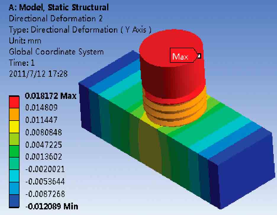
Figure 7 shows the displacement of the split bolt. We can see that the maximum displacement in the Y component is located on the top surface, and its value is 0.018 mm.
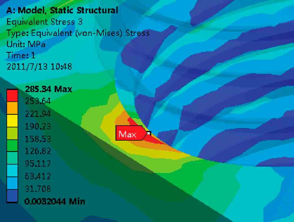
Figure 8 shows the von Mises stress of the split bolt. We can see that the maximum magnitude is 285 mPa.
In Figure 9, we zoom in to where the maximum von Mises stress takes place. The maximum point appears at the joint between the top portion of the head and the bottom section of the studs. Its value is 285 mPa. If the stress value were more than the allowable value of the material, fracture would occur on the head of the bolt.
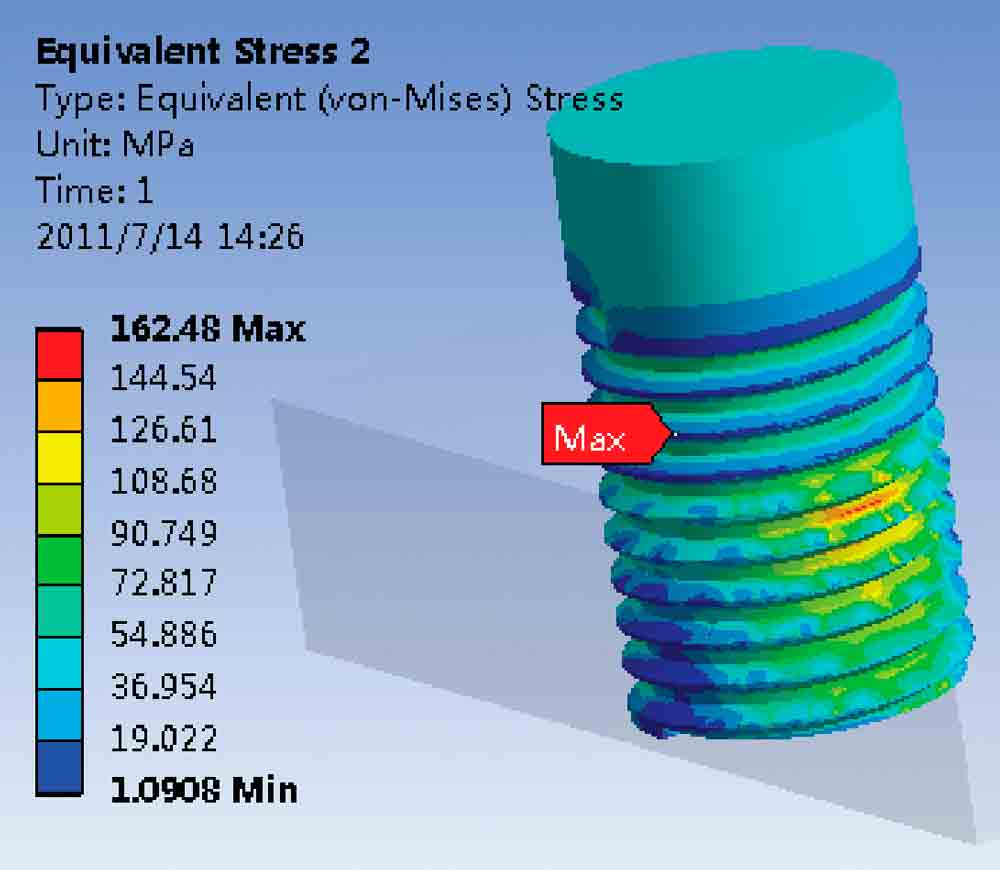
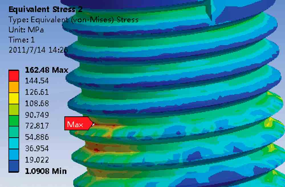
Figure 10 shows the von Mises stress of the studs on a split bolt. We can see that the magnitude of maximum von Mises stress is 162 mPa. The maximum appears in the first circle of studs. With the increase of the lap of the studs, the force decreases gradually, which corresponds to the actual condition.
In Figure 11, we zoom to the area where maximum von Mises stress occurs in the studs.
Figure 12 shows the displacement of the integral bolt. We can see that the maximum displacement in the Y component is located at the top, and the value is 0.011 mm.
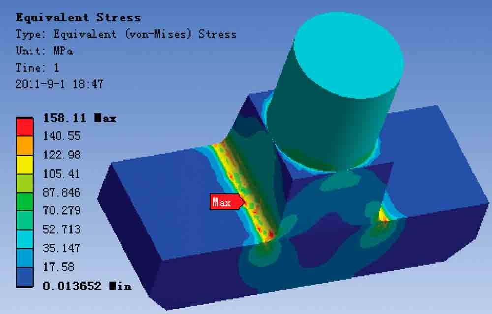
Figure 13 shows the von Mises stress of the integral bolt. We can see that the magnitude of maximum von Mises stress is 158 mPa.
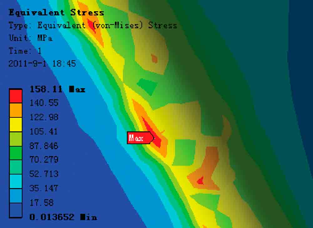
In Figure 14, we zoom to where the maximum von Mises stress occurs on the integral bolt.
Conclusion
After comparing the previous calculations, we can draw the following conclusions: the displacement of the integral bolt in the Y component has little difference with that of the split. The integral is 0.018 mm, while the split is 0.011 mm.
The von Mises stress of the split bolt’s studs is smaller than that of the head of the bolt, and the maximum point appears at the joint between the top portion of the head and the bottom section of the studs. In this place, since the whorl needs to be added and the surface would be the smallest, stress would be concentrated. In conclusion, the strength of the joint between the head of the bolt and the studs is the key factor that determines the strength of the entire bolt. The head of the bolt and the studs are not separated, and, consequently, the smallest surface wouldn’t occur; thus, it has more powerful bearing capacity. The integral bolt is 1.8 times higher than the split from the way of the maximum stress.
References
[1] Yang, J.G.; Murray, T.M.; Plaut, R.H. Three-Dimensional Finite Element Analysis of Double Angle Connections Under Tension and Shear. Virginia Polytechnic Institute and State University; 1999.
[2] Yorgun, C.; Dalc, S.; Altay, G.A. Finite Element Modeling of Bolted Steel Connections Designed by Double Channel. Istanbul Technical University; 2004.
[3] Zhong-he, Chen; Wei-qiang, Wang; Le-wen, Zhang. FEM Analyses of Stress and Deformation of a Flexible Inner Pressure Bolt. School of Mechanical Engineering; Shandong University, 2008.
[4] Bursi, O.S. and Jaspart, J. P. Benchmarks for Finite Element Modeling of Bolted Steel Connections. University of Trento; 1997.
[5] Zhaohui, Zhang. ANSYS 12.0 Resolution Structural Analysis Engineering Application [M]. Beijing: Mechanical Industry Press; 2010.
[6] Wei, Liu. Into a High-Dimensional, in Guangbin: ANSYS 12.0 Collection [M]. Beijing: Electronic Industry Press; 2010.

Figure 1: The joint between the head and the studs A and B 
Figure 3: Meshing the model of the split bolt 
Figure 4: The model of the integral bolt in Pro/Engineer 
Figure 5: Meshing the model of the integral bolt 
Figure 6: Load and restriction A 
Figure 6: Load and restriction B 
Figure 7: The displacement of the split bolt in Y component 
Figure 8: The von Mises stress of the split bolt 
Figure 9: Zoom of the von Mises stress on the split bolt 
Figure 10: The von Mises stress of the studs on the split bolt 
Figure 11: Zoom of the von Mises stress on the split bolt’s studs 
Figure 12: Displacement of the integral bolt in Y component 
Figure 13: The von Mises stress of the integral bolt 
Figure 14: Zoom of the von Mises stress on the integral bolt


Get more of Elevator World. Sign up for our free e-newsletter.


