High-Speed Elevator Machine Design and Development
Mar 1, 2025

An investigation into rope life and bearings’ failure
Key words: High-speed elevators, Permanent magnetic (PM) motor, Torque, Motor size, Diameter of the driving sheave D, Diameter of the ropes d, Ratio of D and d, Worn-out, Bearing failure, Number of ropes, Weight of the suspension ropes, Weight of compensation ropes
Abstract
Nowadays, permanent magnet (PM) motors, instead of AC geared machines or DC gearless machines, are widely used in machine-room-above elevators. The size of a PM motor is determined by the torque applied to it, as Torque = Driving Force x Radius. To minimize torque and thereby reduce manufacturing costs, the radius of the driving sheave should be as small as possible.
Traditionally, the diameter of the sheave is based on the standard for steel ropes, which requires it to be at least 40 times the rope diameter (d). However, the code and standard are the minimum requirement for safety rather than quality, in order to have an acceptable quality for the elevators, for mid-rise or high-rise units, the ratio between D and d must be greater
than 40.
The maximum lifespan of the ropes and minimum diameter of the driving sheave, the maximum weight of the ropes (including compensation ropes) and the minimum diameter of the sheave are two pairs of contradictions. If D/d=40 is applied for all the elevators, massive problems will occur. Therefore, a few suggestions regarding D/d are given by your author:
1. Background
Your author’s article MRL Lift Design and Development was published in ELEVATOR WORLD in August 2020 and EW Middle East in Q4 2020 (in English and Arabic).
Because machine-room-less (MRL) elevator design is based on the PM motor, it is imperative to select the right PM motor as the first consideration. Thus, I have undertaken massive research on PM motors since 2004; the key points to select the PM motors are:

- The size of the PM motor is determined by applied torque rather than power.
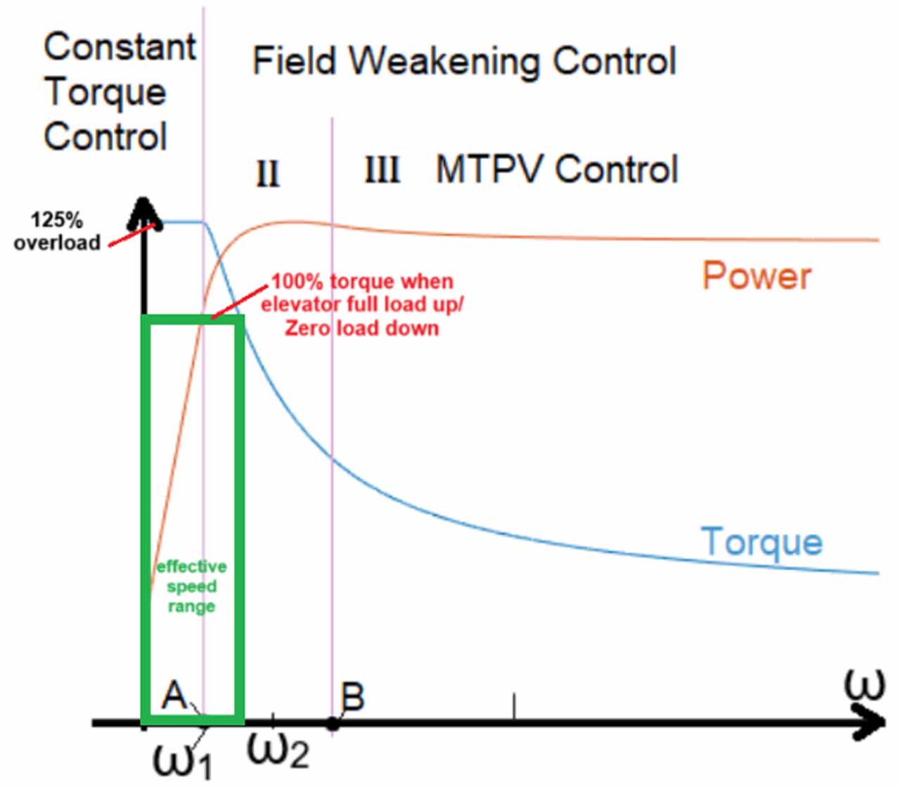
- The power of the PM motor is variable in the effective speed zone (Figure 7) unlike the conventional AC motor.
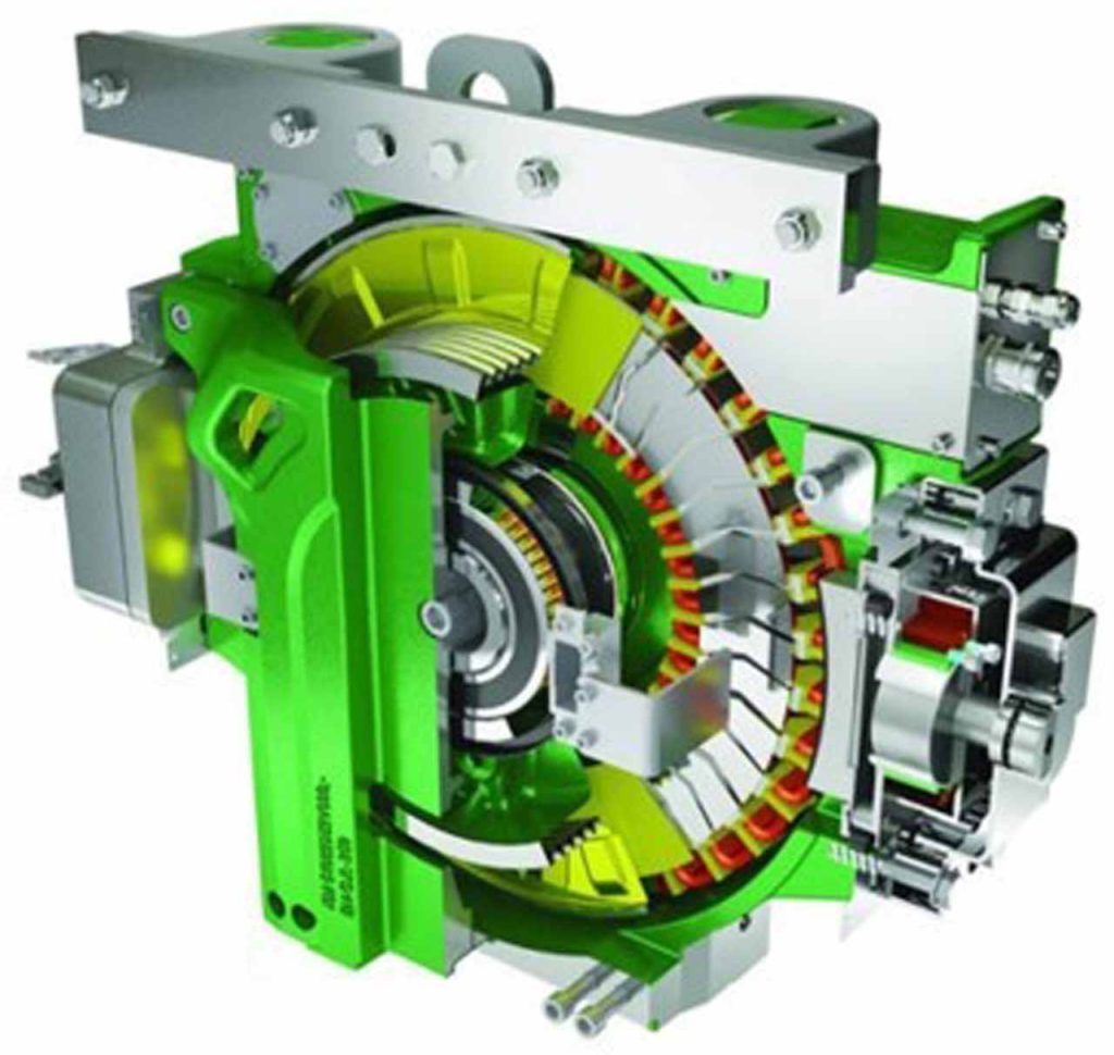
- Compared to a pencil-style conventional PM motor, a disc/flat PM motor is always the first choice for MRL elevator design.
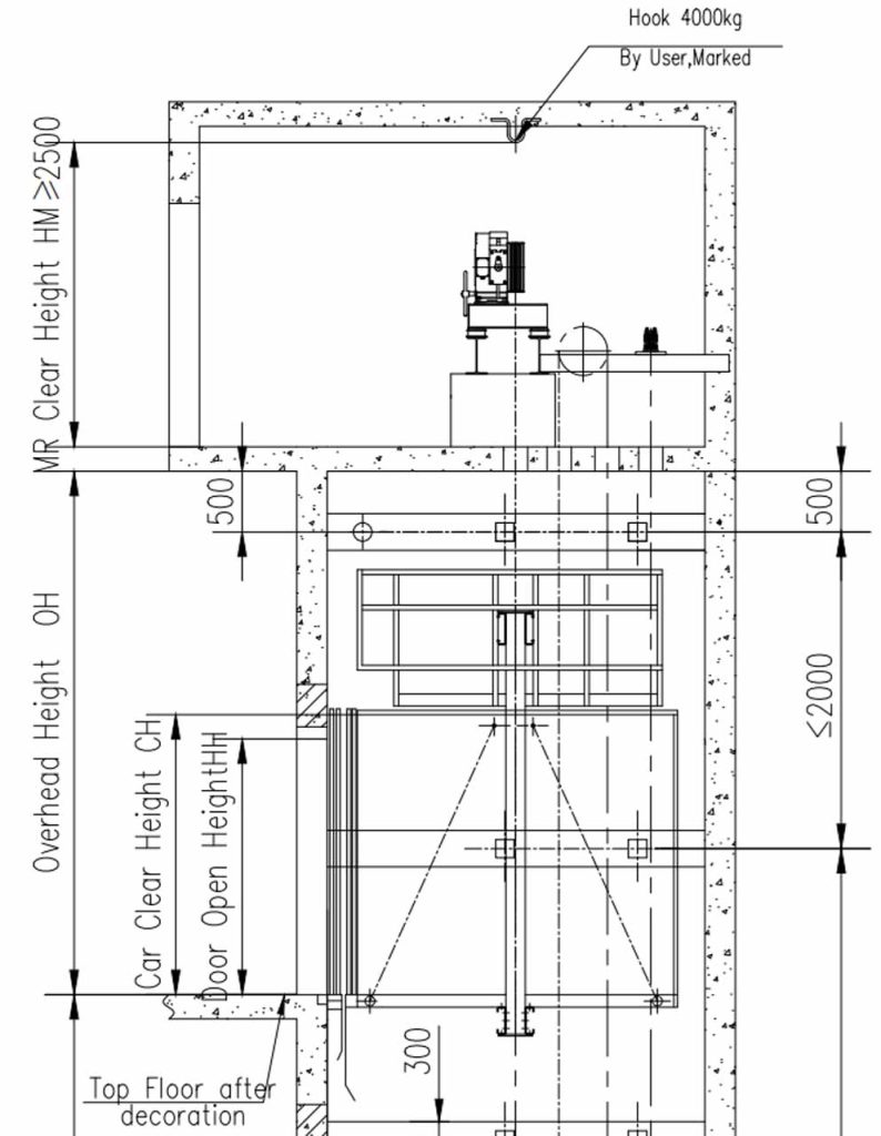
Also, your author has experienced some tender submissions that used MRL elevator solutions for machine-room-above elevators in order to reduce cost to a minimum, particular attention must be paid to those “small machine room” elevators for mid-rise buildings. Simply moving the machine of an MRL elevator out of the shaft to the machine room to build a machine-room-above elevator is not acceptable.
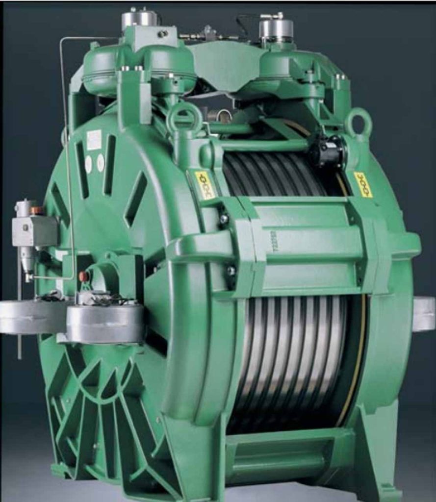
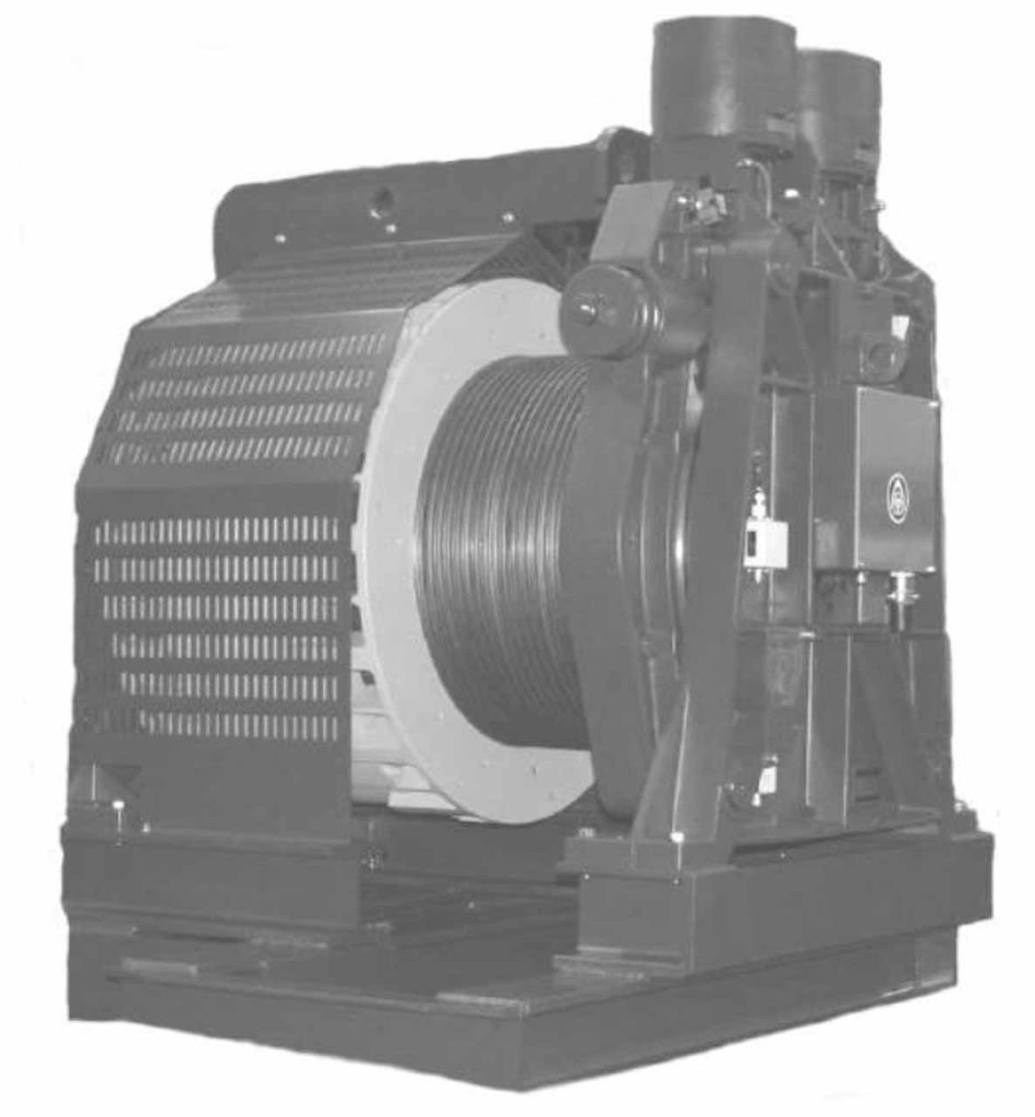
Figure 2 is a tender submission for a 2500 kg service elevator in an 18-floor office building. The specifications require the elevator to have a speed of 1.6 m/s, and the machine must be flat style with a minimum diameter of the driving sheave D/ diameter of the rope d to be not less than 45, and the roping shall be 2:1. But the tender submission was that the machine had the D/d=40 with 4;1 roping at a maximum speed of 1.0m/s.
2. The Issues
Your author was invited to investigate a problem with passenger elevators in a luxury hotel in China in March 2024. The travel height is 330 m, and the four 1600-kg passenger elevators, with a speed of 10 m/s, had already had two rope replacements since the hotel opened 14 years before.
Besides this, I was told that not only the driving sheaves were badly worn, but also the bearings in the machines had been replaced at least once in less than a decade. In addition, some of the driving sheave shafts were seriously damaged due to the failures of the bearings.
The ropes’ diameter, d=19 mm, was found on the name plate of the machines and the number of the ropes was 10. The driving sheaves have a diameter D= either 900 or 760 according to the O&M manual, but it should be 760 by visual measurement. If so, D/d=760/19=40, which just met the minimum requirement of the code and standard.
In contrast, there were two service elevators with the same capacity, but the speed was 7 m/s. They had exactly the same machines, but the number of the ropes was nine instead of 10. Those two service elevators were very busy, working all the time every day, but they didn’t have the above-mentioned issues.
Checking with other elevator manufacturers’ data, manufacturer A has the 1600 kg lift with a speed of 10 m/s, using nine d16 ropes and the driving sheave has diameter, D=900mm, D/d=900/16=56.25. Alternatively, manufacturer B has the 1600 kg lift with a speed of 10 m/s, using 10 d16 ropes. The driving sheave has a diameter of D=860mm, D/d=860/16=53.75. From here, it can be seen: If D=900, the rope diameter d=16 mm with nine ropes is the best option, as the total weight of the ropes is the least.
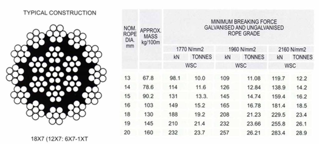
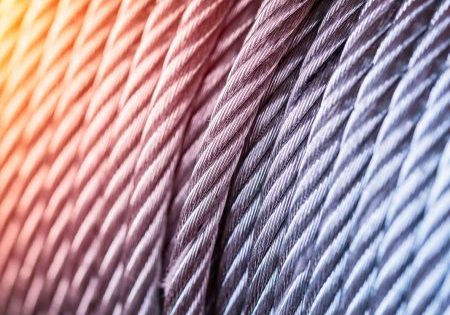
From Figure 3, d16 rope has a mass of 1.03 kg/m. If the travel height is 330 m, including the compensation ropes. The total weight of the 10 d16 ropes is 6798 kg and the total weight of the nine d16 ropes is 6118 kg.
The d19 rope has a mass of 1.45 kg/m. If the travel height is 330 m, include the compensation ropes. The total weight of the 10 d19 ropes is 9570 kg. The total weight of the nine d19 ropes is 8613 kg; the difference (the weight of a single rope) is 957 kg.
The difference between 10 of the d19 ropes and 10 of d16 is 9570 kg-6798 kg=2772 kg. As the ropes are double wrapped, the static loads caused by the 10 d19 ropes on the driving sheave is 4026 kg greater than 10 d16 ropes. The static load caused by the 10 d19 ropes on the driving sheave is 6904 kg (nearly 7 t), greater than nine of the d16 ropes.
3. The Reasons
The MRL elevator is the consequence of the innovation of PM motors. Nowadays, PM motors, instead of AC geared machines or DC gearless machines, are widely used in machine-room-above elevators. Though the PM motor is small, it can produce high torque to directly drive the car and counterweight via the ropes in an effective RPM range of one thousandth to 100 thousandth versus traditional inductive motor 10 thousandth to 1,000 thousandth of nominal rotary speed under 50 Hz AC power supply. Therefore, the gear box can be removed from the lift machine.
3.1 PM Motor Characteristics
T = BLR2πRA = 2BA(πR²L) = 2BAV[1]
where T=torque (total), B=magnetic field strength, L=conductor length in the magnetic field, R=equivalent radius of the motor, and V=motor volume (motor equivalent section of X length L).
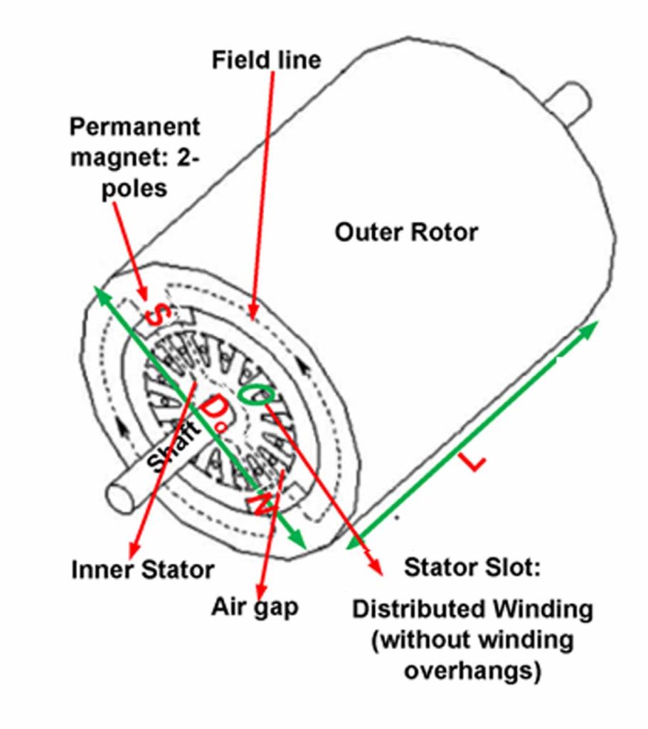
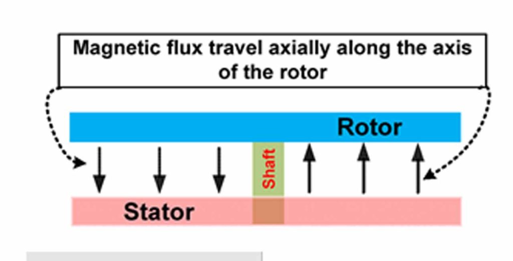
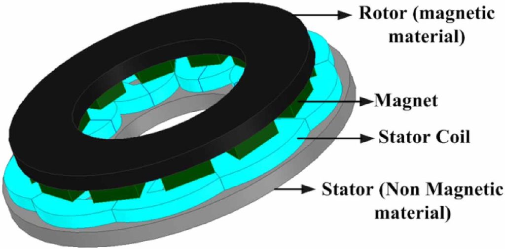
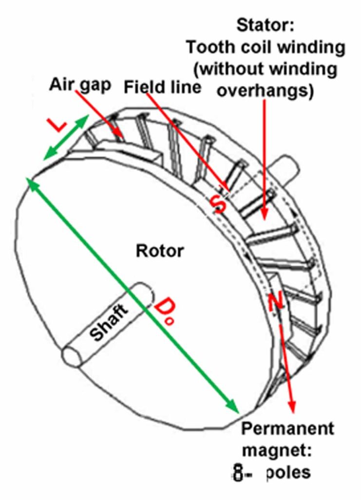
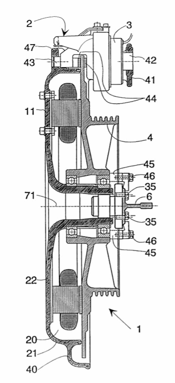
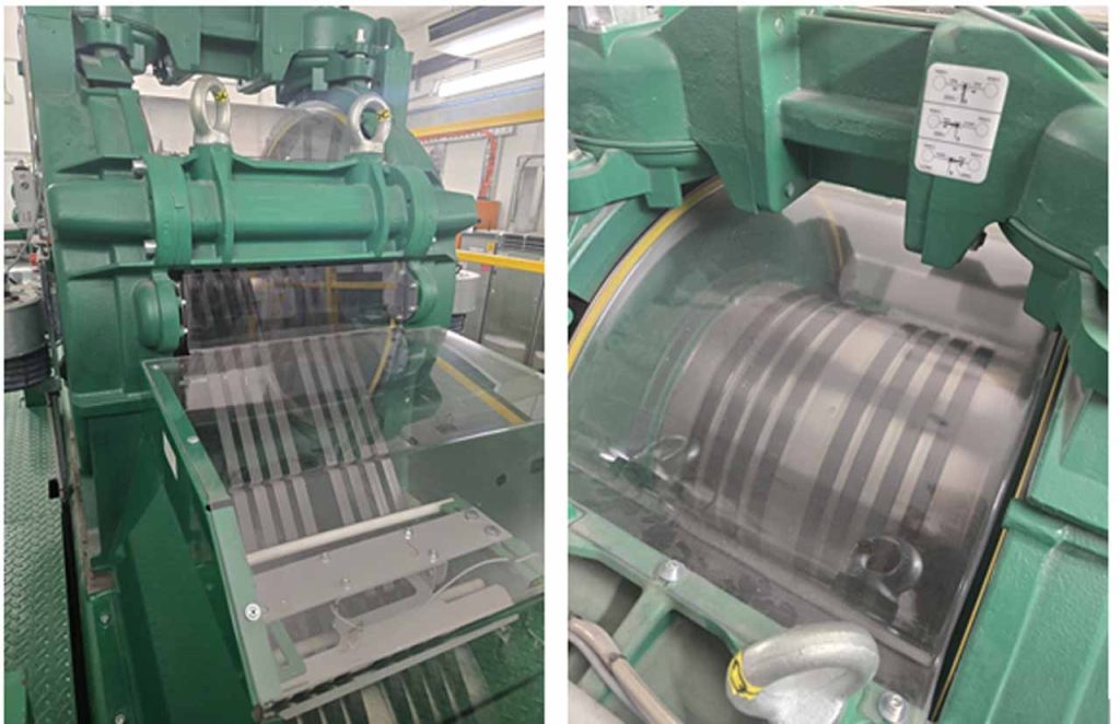
Due to magnetic saturation, magnetic field strength cannot be increased infinitely. To increase torque, only two ways are available: increasing the motor’s diameter and/or increasing the motor’s length. That is why PM motors are usually made flat (skinny but with large diameter) to obtain the highest possible torque. Another purpose of a large-diameter rotor is to obtain a larger ratio between the rotor and driving sheave as shown Figure 12.
As the torque is proportional to the square of the radius, it is imperative to begin with a (flat) PM motor when designing MRL lifts.
3.2 Relationship Between D/d and Rope Life
F = T/r
where F = driving force, T = torque, and r = radius of the driving sheave. One way to have enough F is to make the radius of the driving sheave as small as possible. However, according to the code and standard for elevators, the ratio between the pitch diameter of sheaves, pulleys or drums, and the nominal diameter of the suspension ropes shall be at least 40, regardless of the number of strands of the suspension ropes.
With a pencil-style PM motor, D has to be as small as possible, which is why some elevator manufacturers have chosen to use belts instead of ropes to drive the car and counterweight. It is important to note that D/d should be at least 45; otherwise, the ropes will be worn out very quickly — possibly reduced to less than two years for a very busy elevator.
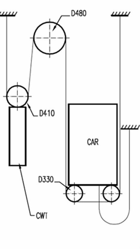
Figure 4: A typical six-rope arrangement: rated load=1000 kg, speed=1 m/s, car weight=1150 kg and rope diameter=8 mm
The results of calculations of different (D Driving Sheave Diameter)/d (Rope Diameter) using a rope lifecycle calculator supplied by PFEIFER Drako:
- When D = 320 mm, d = 8mm, and D/d = 40, average lifecycle = 542,000.
- When D = 360 mm, d = 8 mm, and D/d = 45, average lifecycle = 1,393,000 (2.57 times that of #1 above).
- When D = 400 mm, d = 8 mm, and D/d = 50, average lifecycle = 2,011,000 (3.71 times that of #1 above).
- When D = 480 mm, d = 8 mm, and D/d = 60, average lifecycle = 3,526,000 (6.5 times that of #1 above).
- There are many MRL elevators in low-rise residential buildings in Europe for which D/d = 40 may be acceptable. As the machines of modern MRL elevators normally use PM motors, some manufacturers may use D/d as close to 40 as possible. If so, particular attention must be paid to the rope lifecycle calculation, especially for lifts to be installed in office buildings.
4. Solutions
Your author consulted on a 20-floor office project in the past. The diameter of the driving sheave was D=600 mm, the ropes diameter d=13, then, D/d=600/13=46.15. The capacity was 2500 kg at the speed=3.5 m/s with 2:1 roping. The rope life was the biggest concern at that time. Finally, the elevator contractor agreed that the comprehensive maintenance would include 10 years’ rope life guarantee.
In this case, replacing the machine is impossible. As the roping is double wrapped, it is also impossible to use flat carbon fiber ropes instead of round steel ropes. As a result, reducing the speed from 10 m/s to 7 m/s with nine ropes is the only feasible solution.
Without a proper traffic analysis, just from your author’s experience, the four 1600 kg passenger elevators at 7 m/s serving the hotel floors at the top of the mixed-use building should be good enough, and the performance should be able to meet the design criteria.
5. The Two Types of Elevator Machines
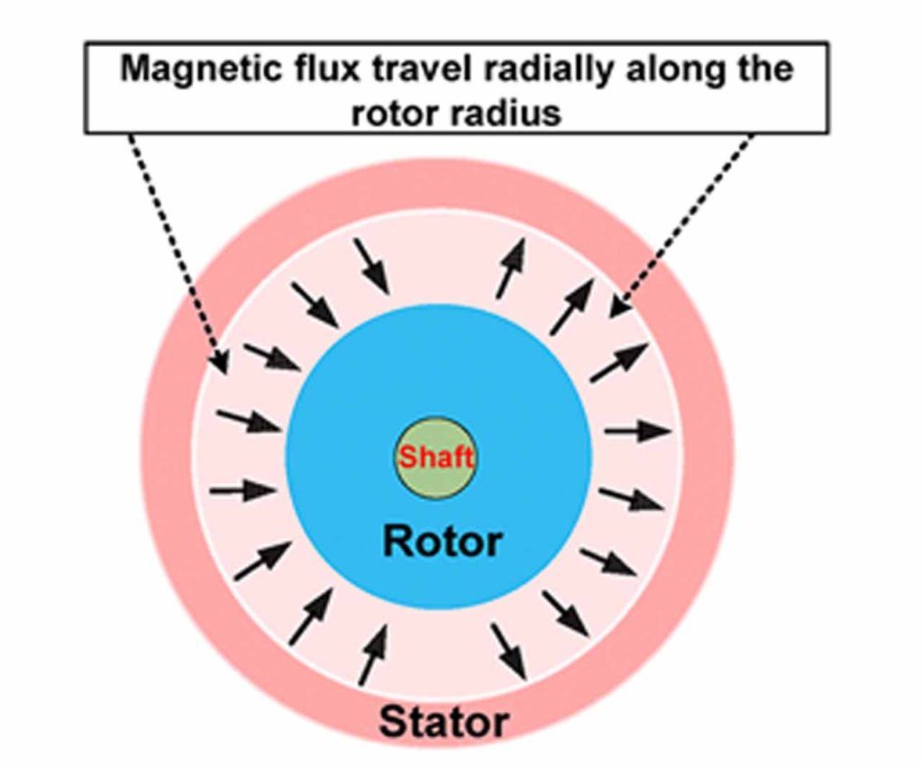
As your author had to search for information about high-speed lift machine design, a lot of lessons have been learned from this investigation, especially about the types of PM motors: Two types of electric machines are used in various applications; they are radial-flux permanent-magnet (RFPM) machines and axial-flux permanent-magnet (AFPM) machines, each with its own advantages and disadvantages.
Advantages of RFPM Machine
- High Power Density: They can generate more power in a smaller volume, making them suitable for applications where space is limited.
- Mature Technology: RFPM machines have been in use for a longer time and are more mature technology, which means there is a well-established supply chain for components and a larger body of knowledge available for design and optimization.
- Lower Manufacturing Cost: In some cases, RFPM machines can be less expensive to manufacture compared to AFPM machines, especially for lower power applications.
- High Efficiency: RFPM machines can achieve high efficiency levels, especially when optimized for specific applications.
Disadvantages of RFPM Machine
- Higher Weight
- Lower Torque Density: They may require larger dimensions to achieve the same torque output.
- Limited Cooling Options: Cooling the rotor of an RFPM machine can be more challenging compared to AFPM machines, potentially leading to thermal management issues in high-power applications.
The basic formula for AC motor speed: RPM = 120*F/P. F is the electrical supply frequency in hertz (Hz), and P is the motor’s pole number. The maximum speed of a PM motor under 50 Hz AC power supply can be regarded as the nominal or reference speed. The power of a rotating body can be expressed as P = T ω, T = torque or “moment” (Nm), ω = angular velocity (red/s)(Figure 7) and the power output is a constant; therefore, the effect range of a PM motor is one to 100 thousandth of nominal speed (under 50 Hz).
Advantages of AFPM Machines
- Compact Design: It can be advantageous in applications where space is limited or where weight reduction is critical.
- Higher Torque Density: They can achieve higher torque output in a smaller package.
- Efficient Cooling: The axial arrangement of the flux path in AFPM machines allows for more efficient cooling.
- Flexible Installation: AFPM machines can be easily integrated into various configurations, which can simplify installation and reduce maintenance requirements.
Disadvantages of AFPM Machines
- Higher Manufacturing Cost
- Limited Supply Chain: The supply chain for components specific to AFPM machines may not be as well-established as it is for RFPM machines, which can lead to longer lead times and higher costs for specialized components.
- Complex Design: The design of AFPM machines requires careful consideration of factors such as magnetic flux paths and cooling channels.
In the addition to the axial-flux PM motors, a Chinese expert asked your author a question: “For those 2250 kg/2250 kg double-deck elevators at the speed of 10 m/s, why does one manufacturer’s machine have a weight of 7500 kg, while its competitors’ machines normally have a weight of at least 15,000 kg?” My answer was that the machine has double-side axial-flux PM motors instead of single-side radial-flux PM motors.
Actually, checking with the manufacturer’s sales brochure, the 2250 kg/2250 kg double-deck elevators at 10 m/s with an output power of 330 kW and D=1200mm, the weight is 6150 kg rather than 7500 kg. The ropes are 14 X d18, 13 x d19 mm or 12 X d22. I think 13Xd19 is the best option, where D/d=1200/19=63.15.
| The problematic RFPM with Inter Rotor | TKE DAB 530L RFPM with Exter Rotor | KONE AFPM EcoDisc MX40 | |
| Traction Sheave D | 900/760 mm | 800 mm | 1,000 mm |
| Maximum Power | 110.4 kW | Not given | 125.0 kW |
| Maximum Speed | 7.0 m/s* (10 m/s N/A) | 8.0 m/s | 8.0 m/s |
| Maximum Loads | 1600 kg (1:1) | 1350 kg (1:1) | 2250(1:1) |
| Maximum Nominal Torque | Not given | Not given | 6500 Nm |
| Maximum Load | 393 kN (D wrapping) | 450 kN (D wrapping) | Single wrapping |
| Max Acceleration Torque | Not given | Not given | 19000Nn |
| Travel Height | ≤ 500 m | ≤ 220 m | ≤500 m |
| Rope grooves | 9 X d19 (7.0m/s) 10 X d19 (10.0m/s) | 10 X d16 | 10 X d16, 9 X d18, 9 X d19 |
| Weight | 7200 kg | 5500 kg | 2700 kg |
Figure 13: Comparison table of the three elevator machines for 1600 kg at 8 m/s
6. Conclusion
Your author believes that the flat steel ropes, carbon fiber rope and axial flux elevator machine will be the direction of product development for high-speed elevators in the short-term future. From this investigation against the rope life and bearings’ failure, the following conclusions can be drawn:
- As the total weight of the 10 d19 ropes (including compensation) is 9570 kg, which is 5.98 times the capacity of 1600 k, reducing the capacity from 1600 kg to 1350 kg will only be able to reduce the total weight of the whole assembly by 250+0.5X250=375 kg. It will be of little help to improve both the life of ropes and the life of the bearings.
- The elevator manufacturers didn’t have the right machines for 10 m/s single-deck passenger elevators. As a result, “a dog was employed to draw a horse carriage” (Figure 1).
- When using a lower-rated machine for the elevator with a speed of 10 m/s, in order to have enough driving force as (F=T/r), the diameter of the driving sheave will have to be as small as possible, which is not 900 mm but 760 mm. Otherwise, 9Xd16 rope would have been used for the machines.
- Because a 760-mm diameter of driving sheave has shorter contact length than a 900-mm diameter for the d16 ropes, the friction will not be enough. As a result, the rope diameter will have to be increased to d19 instead of d16, but 10 d19 ropes will considerably increase the weight of the ropes (including compensation); therefore, the bearings were seriously overloaded. Also, as D/d is just equal 40, the 10 d19 ropes are very likely worn out within five years.
- The speed of 10 m/s is 42.8% faster than 7 m/s, along with the speed increasing and the excessive rope weight. The 42.8% longer acceleration and deceleration time will cause the bearings to fail in a few years. On the other hand, 10 m/s speed may be out of the effective speed range of 7 m/s PM machine (Figure 7).
- The biggest disadvantage of the Axial flux machine is the manufacturing cost as a result of limited supply chain. However, compared with the huge benefit brought into the high-speed elevator machines, the additional cost can be ignored. On the other hand, the technology of the Axial flux machine has been well established, and the patent of the axial flux elevator machine (Figure 12) had been expired since 2016, so the manufacturing costs of Axial flux machines are expected to become lower and lower.
The Axial flux single-wrapping elevator machine is the first choice for high-speed elevators, especially for double-deck elevators, because they are simplest in construction, and the weight of the machine is less than half of the traditional radial flux machine.
When the travel height is greater than 500 m, the Axial flux l elevator machine with the lightweight carbon fiber ropes should be seriously considered.
7. Author’s notes
The codes and standards are the minimum requirement for safety rather than quality. For elevator manufacturers (such as the one in Figure 2), just matching the minimum requirement of safety to supply their products to the market is not acceptable.
D/d of at least 40 is the minimum requirement of safety, but it is not suitable for all elevators. Therefore, a few suggestions are given by your author:
- When the speed of an elevator is less than (including) 1.6m/s, D/d is allowed as a minimum at 40.
- When the speed is greater than (including) 2 m/s and less than (including) 3.5 m/s, D/d shall be at least 45.
- When the speed of an elevator is greater than (including) 4 m/s but less than (including) 7 m/s the D/d shall be at least 50.
- When the speed of an elevator is greater than (including) 8 m/s, D/d shall be at least 55.
- The friction coefficient between steel ropes and iron driving sheave is typically 0.15-0.3, and it is very stable. But the friction coefficient between the coated steel belts is not only very wide (0.176-0.784).[6] Also, the longer it is in service, the bigger the coefficient. This will cause over traction. Non-metal rope is believed to have similar friction coefficient with coasted steel belts. It is why metal to metal is used for the friction as the traction force in vertical transportation (VT). When the elevator car is going up at high speed but an emergency stop occurs, if the friction is too big the non-metal ropes and the driving sheave will have little sliding friction. This will cause a huge force to stop the counterweight going downward. As the impulse F×Δt=M×(V2-V1), because the Δt is too short, F will be very big, and it will cause big problems in the whole system. That is why your author thinks ultralight ropes are not feasible for high-speed elevators. However, putting ABS (anti-lock braking systems) on the brakes on the elevator machine might be a solution.
References
[1] MRL Lift Design and Development, ELEVATOR WORLD August 2020 Issue and EW Middle East in Q4 2020.
[2] A systematic review on current research and developments on coreless axial-flux permanent-magnet machines – Habib – 2022 – IET Electric Power Applications – Wiley Online Library
[3] PMSM Drive Characteristics and Constraint Curves, uk.mathworks.com
[4] KONE Sales Brochure
[5] THYSSENKRUPP DRIVE DAB530 OPERATING MANUAL Pdf Download | ManualsLib
[6] Report Investigation Report and Technical Appraisal Report on the “8.26” Elevator Failure Injury Accident in Zhong-Fang Ruizhi International Community, Fu-Rong District.
[7] Linkedin.com
Get more of Elevator World. Sign up for our free e-newsletter.
