Accessibility, Comfort, Aesthetics and Safety
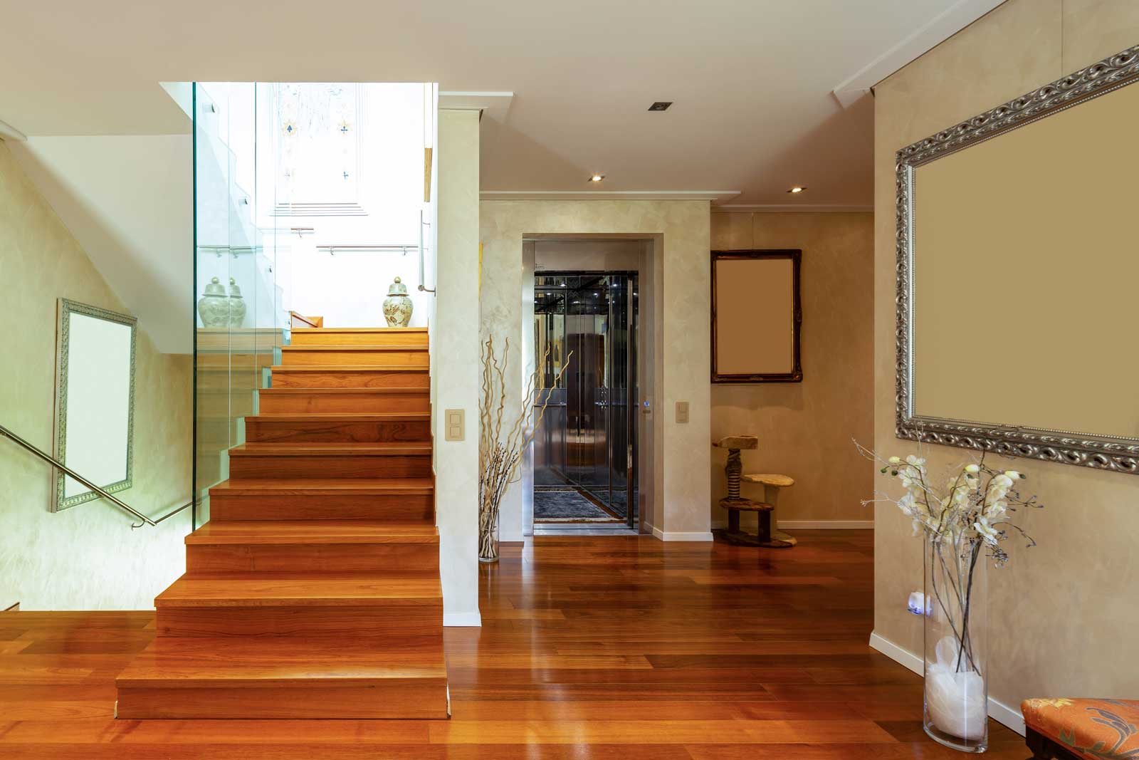
The rapidly changing dynamics of living spaces have brought about the need for domestic comfort and accessibility. Technological systems developed to improve people’s quality of life by providing safe and efficient vertical-transportation (VT) between floors — especially for the elderly and disabled — have begun to play an important role in this regard. Home lifts are among the most preferred technologies for independent living spaces. These VT systems provide domestic comfort and accessibility.
They are typically small-sized lift systems designed for in-home use. These lifts enable individuals or items to move easily and quickly between different floors within the home. They generally have a compact design and occupy minimal space. Additionally, they have advantages such as being easily integrated into existing structures and adapting to various types of homes.
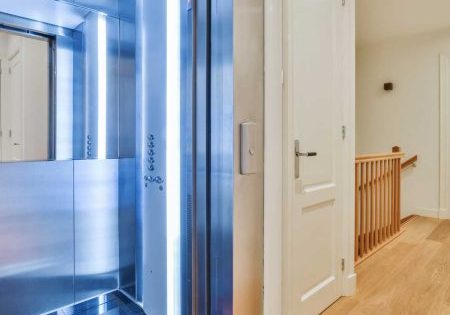
Home lifts provide great convenience, especially for the elderly and disabled, and enhance quality of life by combining aesthetics and functionality. Home lifts prioritize accessibility, but it’s also extremely important to not overlook their luxury features. Wealthy homeowners are increasingly investing in high-quality home lifts that add elegance and sophistication to their living spaces beyond mere functionality.
Homes with lifts are generally perceived as more prestigious and technologically advanced, appealing to a wider range of potential buyers. Moreover, comfort and accessibility can be important selling points, especially for buyers who particularly appreciate these features. Therefore, installing a lift in a home is not just an investment in your current lifestyle, but it can also be a wise financial decision for the future.
Home Lifts for Low-Rise Buildings
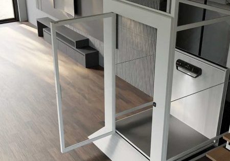
Besides meeting VT needs in low-rise buildings, a home lift adds value to the space with elegant and minimalist design. Wide glass panels and transparent doors with modern lines offer a look that harmonizes with other decorative elements inside the home. The aesthetic value stands out with the choice of materials and color options used. Different cladding options can be used to match a home’s style and decoration. The cladding, color and design chosen to suit the space ensure the lift’s integration with a building’s atmosphere.
In addition, a quiet operation feature and smart control systems significantly improve the user’s quality of life. Thanks to these features, a lift becomes preferable not only for aesthetics, but also for comfort of use. Home lifts can be built in many different design combinations. The most important design variation is the type of drive. The most commonly known drive systems are:
- Hydraulically driven systems:
They usually offer a quieter and smoother ride. Hydraulic systems feature an oil pump, oil tank and hydraulic cylinder. In this method, the movement of the car/platform is achieved through hydraulic pressure applied to the piston.
- Electric (rope-chain-driven systems:
These are powered by an electric motor. Electric home lifts use either gearless machines or geared machines. Gearless machines are the most preferred. In these systems, the movement of the car/platform is provided by ropes or chains driven by the motor.
- Screw systems:
They generally use an endless screw shaft system to provide movement. Rotation is provided by means of an electric motor. The mechanism that carries the lift car up or down is wrapped around this screw shaft. The rotation movement enables the car or platform to move up or down.
- Pneumatic (vacuum) systems:
These types of systems operate with air pressure. They can operate without the need for a shaft and offer an aesthetically pleasing appearance. In these systems, the car moves with the pressure difference created by a vacuum pump.
Each drive type has its own advantages and disadvantages. Additionally, the advantages and disadvantages of the systems vary for each project, depending on the technical specifications of the building and the desired lift (dimensions of the installation area, power/energy, lift capacity and safety). For this reason, the location of the installation and the technical specifications of the desired lift are the most important data in system selection.
Technical Standards and Safety
The design, installation, market release, usage, maintenance, health and environmental impacts, safety and accessibility requirements of home lifts are defined by specific directives and standards. These include:
Related Regulation: Machinery Directive 2006/42/EC(1).[1] The purpose of this Regulation is to establish the fundamental safety requirements that must be followed during the design and manufacturing stages, as well as the conformity assessment procedures that need to be followed and the minimum criteria to be considered when appointing notified bodies to conduct conformity assessments. This is to ensure that machines, when properly installed, maintained and used for their intended purposes, do not harm human health and safety, or, where applicable, domestic animals and property, and can be placed on the market and put into service.
Related Standards: TS EN 81-41:2010 Lifts — Safety rules for the construction and installation of lifts — Special lifts for the transport of persons and goods — Part 41: Vertical lifting platforms intended for use by persons with impaired mobility. The EN 81-41 standard was prepared by the Technical Committee to guarantee both safety and performance by CEN/CENELEC (the European Committee for Standardization). This standard not only specifies the essential health and safety requirements of the Machinery Directive, but additionally outlines the minimum rules necessary for the installation of lifting platforms in buildings/structures.
Machinery Safety Regulation
It includes regulations on the safe design, manufacture and use of machinery. This regulation was established with the aim of protecting the health and safety of users and other people. It outlines the following topics:
- Fundamental health and safety rules concerning the design and construction of machinery
- Placing on the market and putting into service
- Conformity presumption and harmonized standards
- Special measures
- Conformity assessment procedures of machines
- Installation and use of machines
This regulation comprehensively defines all the measures that need to be taken during the design, production, marketing and usage processes to ensure that machines operate in a way that does not harm human health.
Hazards Specified in the TS EN 81-41 Standard
Important hazards are listed in a table in the standard. The main titles of these hazards are:
- Mechanical hazards
- Electrical hazards
- Thermal hazards
- Radiation-induced hazards
- Hazards caused due to neglect of ergonomic principles in machine design
- Hazard combinations
- Hazards arising from malfunctioning of the energy supply, breakdown of machine parts and other functional disorders
- The impossibility of halting the machine under the best possible conditions
- Power supply failure
- Control circuit malfunction
- Connection errors
- Breakage during operation
- Falling or projecting objects or liquids
- Loss of stability/overturning of the machine
- Persons slipping, tripping and falling (machine-related)
- Mechanical hazards and hazardous events
- People falling off the carrier
- Falling or overturning of the people carrier
- Human error, human behavior
TS EN 81-41 Main Safety Rules and Protective Measures
5.1.4.1 Working Areas on the platform
- During maintenance and inspection, any uncontrolled and unexpected movement of the platform must be prevented by a mechanical device. This device must ensure a minimum clearance of 300 mm between the parts of the platform and the solid parts of the lifting path. The device must be electrically monitored.
- A device for emergency operation and testing should be arranged and located outside the lifting path.
5.1.4.2 Work Areas Under the Platform
- A clearance of 500 mm at the lowest position must be ensured during maintenance and inspection. If this can’t be ensured, a mechanical device must be provided to establish this distance. The device must be electrically monitored.
- The doors providing access to the pit must be opened with a key and should prevent the platform from operating.
- The pit floor must support the weight of two people at any position, with a load capacity of 1000 N.
- It must be possible to easily and safely exit the work area.
- A device for emergency operation and testing should be arranged and located outside the lifting path.
5.1.4.4 Machine Outside the Enclosed Lifting Path
- Machines and components positioned outside the lifting path (e.g., control panels, drive machines) should be housed in a cabinet. The machine cabinet must be free of holes, except for ventilation and fire smoke vents. The cabinet door should not open inward, must have a key-operated lock and must be capable of closing and locking without a key.
5.15. Rated Speed
- The speed must not exceed 0.15 m/s.
5.1.6 Rated Load
- It should not be calculated at a value less than 250 kg/m2.
- The maximum permitted rated load should be 500 kg.
- For a single user in a Type A wheelchair or standing; minimum: 250 kg.
- For a user in a Type A or Type B wheelchair with an attendant; minimum: 315 kg. (Type A or Type B wheelchairs are specified in the EN 12183 and/or EN 12184 standards.)
5.1.7 Load Control
- Excessive load on the platform must be monitored. A load is considered excessive if it exceeds the rated load by 75 kg.
5.1.8 Platform Sizes
- The open loading area of the platform should not exceed 2 m2, excluding handrails.
- To accommodate a Type A or Type B wheelchair, the platform floor dimensions in new buildings should meet or exceed those specified in Table 1. For existing buildings, if sufficient space is not available, alternative dimensions may be considered. Local building regulations should be taken into account.
- In buildings accessible to the public, the platform length should be no less than 1,400 mm to provide sufficient space for an attendant.
5.1.9 Mechanical Strength of the Platform
- The platform and combined suspension attachments must be designed to support the maximum static load specified in Table 2, plus an additional 25%.
5.1.11 Protection of Equipment Against Harmful External Impacts
- All mechanical and electrical components must be protected against harmful external impacts (e.g., ingress of water and solid objects/humidity, temperature, corrosion, atmospheric pollution, solar radiation, etc./effects of flora, fauna, etc.).
- For outdoor use, electrical equipment must have adequate protection. The protection level should be no less than IP54, as specified in EN 60529.
5.3 Safety Brake and Overspeed Governor
- The lifting platform must have a safety brake. This rule is not applicable in cases such as the following:
- Directly operating hydraulic jack systems
- If the platform is driven by a self-sustaining rotary screw or nut with a safety nut
- The safety brake must be mechanically activated by an overspeed governor of the platform before the platform exceeds a speed of 0.3 m/s, except in the case of an indirect hydraulic system where the safety brake is activated by the suspension cable or chain breaking or loosening, or by a safety cable where the suspension elements are independent.
- If the overspeed governor is activated by the main suspension chain or cable, the safety brake should also be operable through a mechanism activated by the breaking or loosening of the suspension elements.
- The safety brake should be electrically monitored.
5.3.2 Overspeed Governor
- Any creeping drive in the overspeed governor must be independent of the main creeping drive in the lifting platforms.
- The overspeed governor should be electrically monitored.
5.4 Drive Units and Drive Systems
- Measures should be taken for traction rollers, drums and chain sprockets. (Hazards: Body injury — drums/sprockets that release ropes/chains, loosening — Objects entering between ropes/chains and drums/sprockets)
- The devices used should be designed so that rotating parts are visible, and these devices should not obstruct maintenance work and inspection.
5.4.2 Brake System
- There should be an electromechanical creeping brake that can bring the lifting platform to a smooth stop, hold it in a 25% overloaded position and support the platform with the maximum static load specified in Table 2.
5.4.2.3 Stopping/Level Accuracy
- The stopping accuracy of the lifting platform should be 10 mm.
- The re-leveling accuracy should be maintained within a precision of 20 mm.
- Stopping distances in response to an electrical safety device operation should not exceed 20 mm.
5.4.3 Emergency/Manual Start
- An emergency control device must be available.
- The maximum time required to move the platform to the nearest landing where the door can be opened should not exceed 15 min.
- This emergency operation should only be possible to perform from an external position of the lifting path by an authorized or expert person, with full control over the movement.
- Alternatively, a standby power supply or device can be used to perform the operation.
- In emergency electrical operation, the maximum speed should not exceed 0.05 m/s.
5.4.4 Additional Requirements for Rack Gear and Pinion (Counter Gear) Drive
- The platform should be supported, raised and lowered by one or more pinions (counter gear) and a rack gear coupling. The drive must be performed by one or more motors. Foreign objects must be prevented from entering between each drive or safety pinion and rack gear.
5.4.5 Additional Rules for Rope and Chain Suspension Drive
- The nominal diameters of the ropes should be at least 6 mm.
- The chains must comply with the rules of ISO 606.
- The safety factor should be a minimum of 12 for ropes and a minimum of 10 for chains.
- The minimum number of ropes/chains should be two. Ropes/chains must be independent.
- To equalize the tension of the suspension ropes or chains, there must be at least one automatic device at one end.
5.4.6 Additional Rules for Screw and Nut Drive
- Measures should be taken to prevent the platform from free falling or descending at excessive speeds.
- The safety stopping device should only operate in the downward direction and should be able to stop the relative rotational movement between the platform carrying the maximum working load and the screw nut at the tripping speed of the overspeed governor, ensuring it remains constant. The stopping device should be electrically monitored.
5.4.7 Additional Requirements for Creep/Traction Movement
Traction wheels must be made of metal, however the working surface may contain rubber made of other material. Wear must not reduce traction coupling.
5.4.8 Additional Requirements for Guided Chain Systems
- The platform must be supported, raised and lowered by means of one or more transmission units. Steps should be taken to prevent foreign objects from entering between the chain and chain-related components.
5.4.9 Additional Requirements for the Scissor Mechanism Drive
- All drive mechanisms detailed in the Standard, including their specifications, should be equally applied for the drive of scissor mechanisms.
5.4.10 Additional Requirements for a Hydraulic Drive
- Two drive methods are permitted: Direct motion and indirect motion. The system elements should be designed to withstand forces at the multiples of coefficients specified in the standard.
- A shut-off valve must be available.
- A check valve must be available.
- A pressure-relief valve must be available.
- The flow cut-off valve/rupture valve must be directly connected to the cylinder outlet, and it should prevent the platform from falling in case of any failure in the hydraulic circuit (excluding the jack).
- A combination of a limiter, down direction valve and check valve should prevent the downward speed of the platform with maximum working load from exceeding the rated speed in case of failure of any part of the hydraulic circuit (excluding the jack).
- A limiter should be directly connected to the cylinder outlet and should prevent the downward speed of the platform with maximum working load from exceeding the rated speed in case of failure of any part of the hydraulic circuit (excluding the jack).
- Pressure control should be provided by a manometer.
- An emergency valve that allows the platform to descend manually in an emergency situation should be available.
- A hand pump that allows the platform to move upward should be available.
5.5 Electrical Installations and Equipment
- The lifting platform should be connected to a dedicated power supply that complies with EN-60204-1, terminated with a main switch and fuse or a device that will keep it locked in the “off” position or disconnected state in case of overload. The power supply for the exits should be provided through a 30 mA RCD. The main switch should not cut off any lighting or the power outlets provided for maintenance purposes.
- The lighting on the platform floor, at the platform control devices, and around the exit doors should be no less than 50 lux. In the event of a normal lighting source failure, a lamp should be equipped with an automatic rechargeable emergency power source with a minimum capacity of 1 W. This lighting should automatically activate in the event of a normal lighting source failure.
- The live parts of controllers and electrical safety contacts should be placed inside a protective cover (housing) with a minimum protection rating of IP2X.
- Any single fault occurring in the electrical equipment of the lifting platform should not, by itself, cause a dangerous malfunction in the lifting platform.
- Electrical equipment should not be connected in parallel with an electrical safety device, except where permitted by the standard.
- Control devices should be available on the platform and at each exit.
- The control devices on the platform used to control its movement must be connected in a “hold-to-run” mode.
- A safety stop device compliant with EN ISO 13850, which directly cuts the electrical safety circuit when activated, should be installed on the platform.
- To call for external assistance, passengers on the platform should have access to a clearly recognizable and easily reachable device designed for this purpose. This device should allow for continuous two-way audio communication with a rescue service.
- The emergency alarm device should be equipped with a standby power source (such as a backup and rechargeable battery) that will activate in case of normal power supply failure. The standby duration should be at least 1 h.
- The emergency alarm device must remain operational even in the event of an electrical power supply failure. When connected to the public telephone network, there should be no need for backup power.
5.6 Special Rules for Lifting Platform Enclosures
- When the lifting platform is in contact with the upper mechanical stop, the vertical clearance between the platform floor and the lowest part of the overhead obstacles should not be less than 2 m.
- The lift shaft and platform glass should have the following characteristics based on the outer circumference diameter:
- Tempered, multi-layered: 4+4+0.76 mm (Rmax:1000mm)/5+5+0.76 (Rmax:2000mm)
- Multi-layered: 5+5+0.76 mm (Rmax:1000mm)/6+6+0.76 (Rmax:2000mm)
- The glass panels used in doors should have the following characteristics based on the outer circumference diameter: Tempered: 8 mm (Rmax:100mm); Tempered, multi-layered: 4+4+0.76 mm (Rmax:1000mm); Multi-layered: 5+5+0.76 mm (Rmax:1000mm)
- Glasses that do not meet the requirements must be tested in accordance with EN 81-1:1998 and EN 81-2:1998, Annex J.
5.7 Fire Protection
- Exit doors must comply with the fire protection regulations of the relevant building. EN 81-58 defines the fire testing method.
5.8 Closed Lift Shaft Entrances
- Closed lift shaft entrances should be protected with exit doors.
- The clear width of the platform, its entrance, and exit openings should not be less than 800 mm. However, entrances of 500 mm are permitted by national regulations only for private access buildings for the use of single users (not designed for wheelchairs of type A and B).
- The clear height of the entrance should not be less than 2,000 mm. (In existing buildings, the minimum clear height of the landing door can be reduced, but it should be at the maximum level allowed by the building’s constraints. However, it should not be less than 1.80 m.)
- At the entrance, there should be a threshold or ramp surface to prevent the passage of loads with specified quantities from the platform. A door sill difference greater than 10 mm is not permitted. For differences exceeding 10 mm, a ramp must be provided. Ramp slopes should not be more than the following.
- 1:4 for vertical elevations up to 50 mm
- 1:6 for vertical elevations up to 75 mm
- 1:8 for vertical elevations up to 100 mm
- 1:12 for vertical elevations of more than 100 mm
- During normal operation, the landing door should not be able to open when the platform is more than 50 mm away from the threshold level of the door.
- Each landing door’s lock should be accessible to open from the outside with a special key or tool.
5.9 Platform
- Where movement, steering or lifting mechanisms create a hazard at the edges of the platform, these mechanisms should be protected for user safety. The protection should be unobstructed, solid and continuous.
- Platforms should have a sensitive edge, a photoelectric sensor and a light curtain placed at the base corner of any open side.
- The following equipment should be located on one side of the platform:
- Control devices
- An emergency stop device
- An emergency alarm system control device
- A railing should be installed on at least one wall of the platform. The gripping part of this railing should have a minimum radius of 10 mm, with cross-sectional dimensions between 30 mm and 45 mm. The gap between the gripping part and the fixed wall should be at least 35 mm. If this gap is adjacent to a movable surface of the railing, the minimum size should be increased to at least 100 mm. The height of the upper corner of the gripping part should be (900 ± 25) mm from the platform floor.
- If there is a folding-type seat present, the seat should have the following characteristics:
- The seat height from the floor should be 500 mm ± 20 mm.
- The depth should be between 300 mm and 400 mm.
- The width should be between 400 mm and 500 mm.
In conclusion, home lifts offer an excellent solution for the comfort and accessibility needs of modern homes. They enhance quality of life while ensuring safety and ease of use thanks to their advanced technologies and stylish designs. Lifts provide significant benefits for the elderly and disabled, as well as enhance the value of homes. By paying careful attention to important details when choosing a home lift, it becomes a worthwhile investment that can be safely used for many years.
References
[1] The new Machinery Directive, EU 2023/1230, which has been published. The validity of 2006/42/EC will expire on January 14, 2027.
[2] TR Ministry of Industry and Technology — Machinery Safety Regulation – 2006/42/AT**Official Gazette dated 03.03.2009 and numbered 27158; https://mevzuat.gov.tr/mevzuat?MevzuatNo=12907&MevzuatTur=7&MevzuatTertip=5
[3] TSI Turkish Standards Institute — TS EN 81-41:2010 Lifts —Safety Rules for the Construction and Installation of Lifts — Special Lifts for the Transport of Persons and Goods – Part 41: Vertical Lifting Platforms Intended for Use by Persons With Impaired Mobility.
Get more of Elevator World. Sign up for our free e-newsletter.
