Importance of Thermal Balance for Hydraulic Elevators
Feb 1, 2011
Thermal balance temperature of hydraulic elevators is assessed and recommendations to achieve lower balance temperature are given.
by K. Ferhat Celik and Murad Kucur
This paper was presented at ElevcoN Lucerne 2010, the International Congress on Vertical Transportation Technologies and first published in IAEE book Elevator Technology 18, edited by A. Lustig. It is a reprint with permission from the International Association of Elevator Engineers Iaee (website: www.elevcon.com). This paper is an exact reprint and has not been edited by ELEVATOR WORLD.
Key Words: Heat transfer, thermal balance, hydraulic elevators
ABSTRACT
Heat generation of hydraulic elevator power units is a very important phenomenon and should be kept under control for good ride performance and longer service life. Very low and very high oil temperatures decline ride quality of the elevator. Very low oil temperatures cause sluggish behaviour of control valves and may also lead to cavitation problem whereas, high oil temperatures, apart from declining travel performance, deteriorate lubricating properties and increase contamination level. If it is not cared, a cyclic heat generation process develops, which decreases component life, results in frequent servicing and increases annual cost of the elevator.
A true power unit design should consider thermal balance of the elevator at an acceptable oil temperature as one of the main design constraints. In most cases, coolers can be avoided by a proper design, which reduces energy consumption accordingly.
In this paper, thermal balance temperature of hydraulic elevators is assessed with respect to type of elevators, suspension ratio and various environmental conditions through a derived theoretical model. Recommendations to achieve lower balance temperature for hydraulic elevators are also given.
1. INTRODUCTION
In a hydraulic elevator system energy must be added to the hydraulic oil in order to elevate the car to its destination. An electric motor is needed to drive a pump to convert the mechanical energy into flow. Resistance to flow in the hydraulic system creates pressure whose energy actuates the cylinder of the elevator system. Hence, the complete hydraulic elevator system is actually an energy transfer system. As the energy is simultaneously transformed from one form to another, some of the energy in the system is converted into heat which increases the temperature of the oil in the tank. The oil then naturally dissipates its heat energy to the environment until the temperature gradient between the oil and the ambient temperature equalizes.
Utilisation of mechanical valves (approximately 70%) dominates hydraulic elevator applications because of their inherent advantages on low usage elevators, where oil temperature variation is moderate. On the other hand, ride quality of mechanical valves lowers as working oil temperature range expands. Thus, under expected working conditions, temperature variation of hydraulic oil should be determined prior to the design of the power unit. In industry, some empirical formulae are used to determine whether a cooler is required at the up most working conditions. However, such calculations do not give the complete view for oil temperature variations with respect to the usage of the elevator and environmental conditions such as, air ventilation, ambient temperature, power unit size etc. The present work considers all applicable design parameters and gives a complete picture for a suitable thermalbalance condition, which may not necessitate a cooler.
2. CAUSES FOR OIL TEMPERATURE VARIATIONS
High oil temperature can be caused by internal and external factors. The principal internal sources of heat are the pressure losses (or pressure drops). Excessive pressure losses can occur from flowing through inadequately sized valves or piping, kinked or sharp bends in hose or tubing. Every component added to the hydraulic system introduces a new pressure drop that is converted into heat. Pressure drop of hydraulic components increases as the flow-rate and oil viscosity rise. (It can be shown that the temperature of mineral oil will increase by 0.56°C for every 10bar pressure drop that exists across a flow passage). Heat is also generated by friction losses in the pipework, pump, motor, cylinder seals and in other components. Entrained air in the oil also largely influences the high oil temperature. Additionally, low oil viscosity can contribute to excessive heat generation because it inherently fails to maintain a crucial lubrication film between moving surfaces, resulting in wear and eventually increased leakage. In Figure 1 heat generation cycle is given.
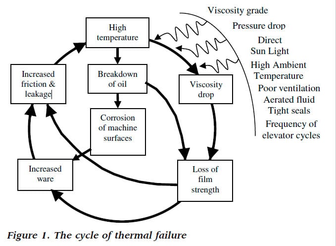
In the up travel, all kind of pressure drops are converted into heat. If the motor is submersed then oil is additionally heated due to the efficiency rate of the motor. Furthermore, longer bypass, acceleration, deceleration and levelling times increase heat generation to a great extent. This is because some of the pressurized oil in these periods by-passes to the tank, i.e., the pressure energy is converted into heat, instead of raising the potential energy of the car. In the down travel, (generally motor is de-energized) potential energy of the car is mostly converted into heat.
Inadequately adjusted pressure relief valves, improper oil viscosity grade, high ambient temperature, incorrect tank location, poor ventilation or/and no external window in the machine room, insufficient tank size and tank design, power units that are exposed to the sun light etc, are some of the external factors that reduce the hydraulic system’s capacity to dissipate heat.
3. EFFECTS OF OIL TEMPERATURE VARIATIONS
Main concerns for variation of oil temperature are; change in oil viscosity and possible breakdown of hydraulic oil at elevated temperatures.
Mechanical valves are adjusted at a mid-value of the working (oil) temperature range. When the elevator usage is low (below 20 cycles/h), working temperature variation will be limited and the elevator would serve satisfactorily. As working temperature range widens with the usage of the elevator, mechanical valves then react differently at very low or high oil viscosities. When oil viscosity is very high, i.e., oil is cold, system operation becomes sluggish and unsatisfactory. For example, start of the elevator may be jerky, acceleration and deceleration times become longer. Thus heating the oil will have a beneficial effect when oil is cold.
Low oil viscosity, on the other hand, makes oil thinner and elevator operation becomes erratic and poor. In this case, acceleration and deceleration times become shorter, speed of the elevator decreases (due to lower volumetric efficiency of the pump) which results in prolonged levelling and longer travel time with mechanical valves (Figure 2). As the travel time extends a cyclic chain reaction initiates between heat generation of the power unit and prolonged travel time. Continued system operation often requires an oil change, seal replacement, and repair of components.
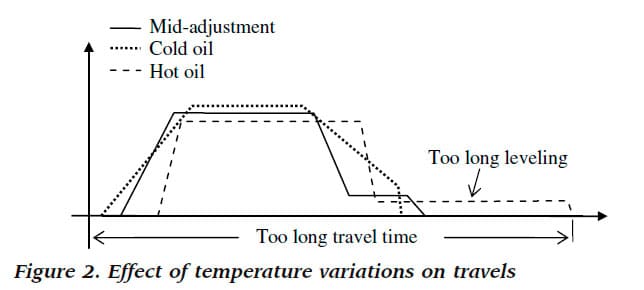
With electronic valves the change of oil viscosity does not normally affect the trip times (deceleration, acceleration, etc) and the elevator speed. Thus, they can be utilized for much higher working temperature ranges than the mechanical valves.
Mineral oil oxidizes even at room temperature but its oxidation rate increases dramatically at elevated temperatures. Oxidization rate of mineral oil normally negligible below 80° and it doubles for every 10°C rise above 80°C. In a hydraulic elevator application normally oil temperature stays below 55°C, however temperature in the pump and in the motor bearings will be higher than the measured oil temperature in the tank. Thus the upper temperature limit of the oil should be kept as low as possible otherwise, service life of the oil as well as system components may deteriorate earlier.
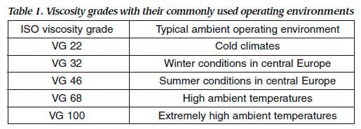
A true selection of the oil viscosity grade considers the average ambient temperature and the usage of the elevator. From the ambient temperature the minimum and from the usage of the elevator the maximum working oil temperatures can be predicted. Viscosity grade numbers that are most commonly used in elevator applications
are listed in Table 1. It is important to note that recommended viscosity grade could be improper as the ambient temperature varies.
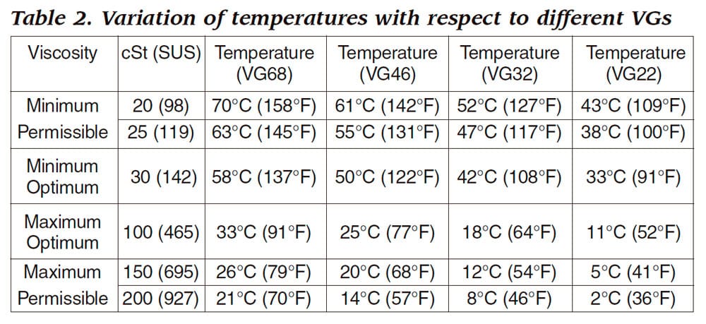
As a general guideline, mechanical valves provide good riding performance at a working oil temperature range of 12 – 15°C and electronic valves at about 35°C (ISO VG 46, VI 100). As the VI increases (>130) these temperature ranges reach 20°C and 40°C respectively. Although it is highly desirable to maintain the oil temperature range as small as possible, the specified temperature limits is not abnormal and can be tolerated with the hydraulic valves that are properly adjusted. In Table 2, optimum and permissible viscosity ranges with corresponding temperature limits are shown for various VGs for VI of 100.
4. HEAT BALANCE CALCULATION
One of the main objectives of the power unit design is to balance heat losses at an acceptable oil temperature by natural transfer from the oil to pipes, actuators and reservoir, and subsequent dissipation to the air. The heat balance calculation requires a true mathematical summation of heat entering and leaving the hydraulic system. In order to obtain a realistic estimate many internal and external factors are to be considered simultaneously. Some of these are;
Average load factor (kload) is chosen as 0.50 (0.4 – 1) to calculate the average load.
Average load = Pay load * kload (1)
Average trip factor (ktrip) is selected as 0.7 (0.5 – 1) to obtain the average trip distance.
Average trip distance (TD) = Max trip distance * ktrip (2)
Average motor starts per hour (z) is the time between two consequent travel cycles (up + down), including door opening-closing, loading-unloading and travel times. It can be given by;
z = 60/(2 * Trip time [min] + 1) (3)
Total trip time (ttotal) can be calculated by using appropriate times in Table 3 and eqn (4).


4.1 Heat Generated by the Elevator
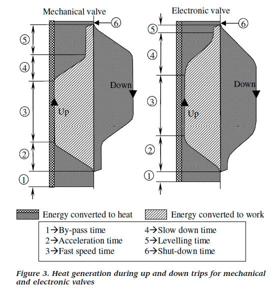
In Figure 3, heat generation cycle of a hydraulic elevator is illustrated. In the up direction, during by-pass, acceleration, slow down and levelling stages the complete or some of pressurized oil is sent to the tank, which generates a lot of heat. In the case of electronic valves, 5 to 7 percent of flow is also by-passed to the tank during travelling at fast speed. This is necessary for controlling the speed of the elevator. However, constant by-pass, acceleration, slow down and levelling times make electronic valves generate a reduced amount of heat in general. Efficiencies of motor and pump also affect the amount of heat generated during the up travel. This is shown with a thin band in Figure 3. In the down trip, the potential energy of the car is mostly converted into heat. The amount of heat load transferred into oil can be calculated as below;
Electric motor and pump efficiencies (hM, hP): Efficiency of electric motors increases with their power ratings. Submersible motor efficiency varies between 75 to 80%. On the other hand, non-submersible motors can have efficiency of 85 to 93%. The screw pump efficiency can be taken between 75 to 81%. The electric motor and the pump heat up the oil in accordance with their efficiencies as below;
WM,P = Motor power * (1 – hM * hP) (6)
Pressure drop (dP): Pressure losses of the hydraulic components in the hydraulic circuit such as control valves, rupture valves, silencers, piping etc, can be obtained from manufacturer’s data sheets. The heat generated due to pressure drops can be calculated as below;
WPressure drop = ∑ Pressure drop * Flow rate (7)
Heat generation due to by-passed oil: This can be calculated as follows;
Wby-pass = ∑6i=1 Wi (8)
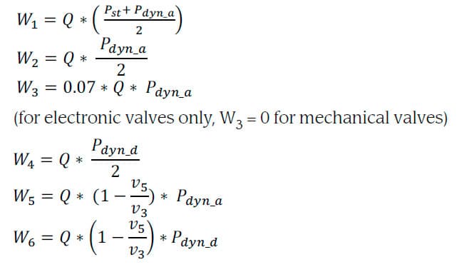
where, v3: fast speed, v5: levelling speed, Pst: static pressure, Pdyn: dynamic pressure (_a: acceleration, _d: deceleration), Q flow rate, and Wi power loss.
Calculation of the static and dynamic pressures can be performed as below:
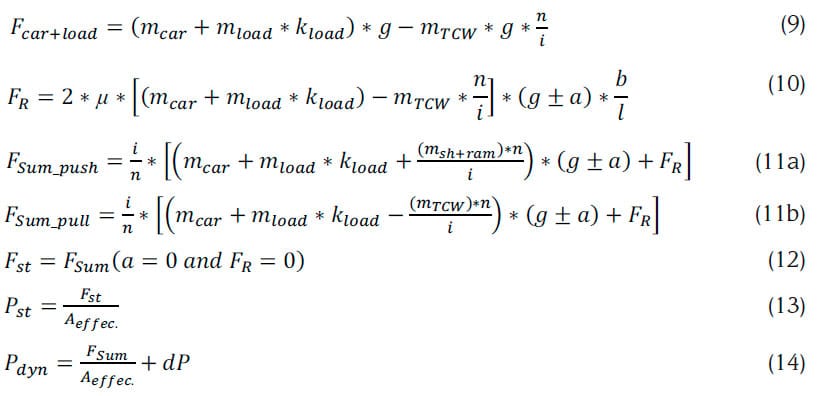
where, m represent masses, F represent forces, g: gravitational acceleration, a: acceleration rate, m: friction factor, kload: average load factor, dP: pressure losses, n: number of cylinders, i: 2 for indirect and 1 for direct system, mTCV: total counterweight mass. When the elevator is push type then mTCV = 0.
Then the total amount of heat generated during up trip;
Wup = WMotor, Pump + Wby-pass + Wpressure drop (15)
Heat generation during down trip: A general equation in the down direction becomes;
Wdw = M * g * h * ktrip (16)

4.2 Heat Dissipated by the Power Unit
Heat dissipates from a hydraulic system in two ways: through natural convection and through forced convection. Natural convection takes place as heat moves from the various system components to the surrounding air because of the temperature gradient. When a heat exchanger becomes necessary the second heat dissipation mode, forced convection, occurs. Radiation, another mode of heat dissipation, is in action too, but its effect is essentially negligible.
4.2.1 Heat Dissipation from the Tank and Exposed Cylinders
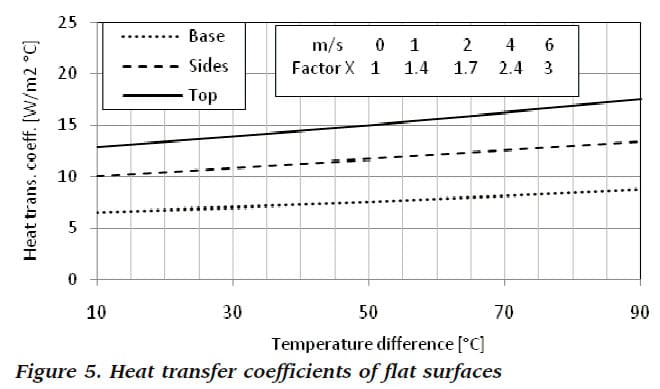
Heat will only be transferred provided there is a temperature difference between the surface and the ambient air. Heat dissipation calculations are much more complex, usually derived from empirical data, or tables based on several assumptions have to be relied upon. Figure 5 provides some typical overall heat transfer coefficients for ‘still air’ conditions from bare steel flat surfaces to ambient air. In there, the multiplication factor is also given when surfaces are in air draft.
The amount of cooling provided by the tank and the cylinder are primarily dependent on their surface area, emissivity, location and the surrounding temperature. The effective coefficient of heat transfer is calculated by using the graphs and the table in Figure 5.
It can be assumed that most heat is transferred from cylinders and from the tank by convection. Thus following formulas for heat dissipation can be written;
Wdis_tank = h * Atank * (Toil – TM.room) (17a)
Wdis_cylinder = h * Acylinder * (Toil – TShaft) (17b)
where, W: dissipated heat power, h: coefficient of overall heat transfer (0.0090 – 0.012 kW/m2°C), A:surface area, T: temperature.
4.2.2 Heat Dissipation by Blowing Air onto the Tank
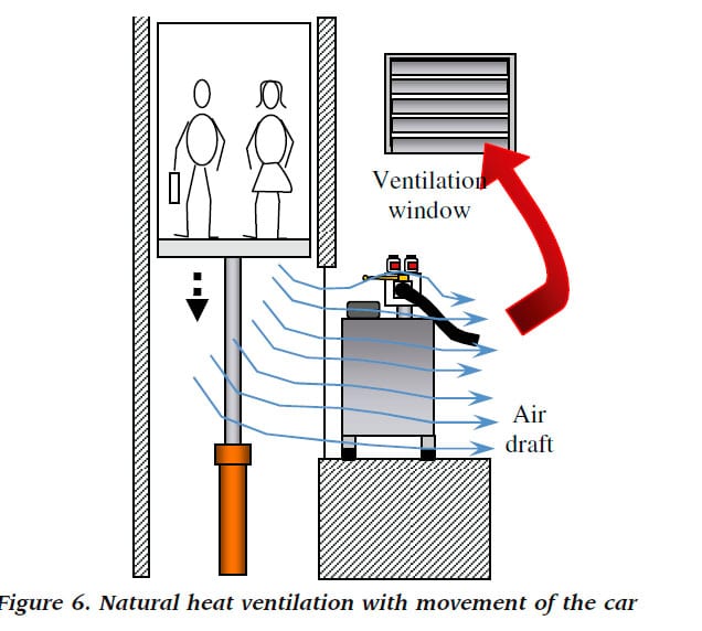
In most cases the elevator shaft is just behind the machine room. Each time the elevator car moves, it conducts a pumping action in the shaft i.e., pushes the air in front of it and sucks the air underneath or vice versa. The pumping action of the elevator car in the shaft can help cooling the oil in the tank and ventilate air in the room. This is schematically shown in Figure 6 where the tank is placed in front of an opening on the shaft wall. The top window in the shaft allows fresh air to enter the shaft and the air under the car is pushed out of the machine room window as the car is doing a down trip. Conversely, fresh air is sucked from the machine room window into the shaft and the air above the car is pushed out of the shaft window. This is called as natural air blow.
4.3. Time Based Calculation for Heat Balance
The heat calculations are normally performed with respect to number of round trips in an hour at a critical condition, where the oil and the ambient temperatures are selected at their limit values such as 55°C and 30°C respectively. If the generated heat power is higher than the dissipated one then a heat exchanger with cooling capacity of that difference is selected. This calculation however, does not consider the temperature variation with time, which is also important to decide on the cooler. Therefore, more comprehensive solutions can be obtained from the below formula based on time parameter. In a true balance what goes in must be accounted for either as a temperature increase or as a transfer of heat out of the system. Thus,
Energyloss = Eloss = Energyabsorbed + Energydissipated (18)
The general relationship is;
Eloss * dt = (∑ c * MTotal) * dTD + (∑ k * A)TD * dt (19)
where, t: time, c: mean specific heat, MTotal: combined mass, TD: temperature difference, k: overall heat transfer coefficient and A: surface area.
If the differential equation is arranged and integrated between limits of TDi (initial TD) and TD;

The steady-state temperature is reached when t approaches infinity, thus max. TD is obtained by;

5. RESULTS
In order to show simulations of balance temperatures, an indirect elevator was modelled as a standard push type and also as a pull type with counterweight. For both types, simulations were run, using mechanical and electronic control valves, under varying design conditions. In these simulations, tank oil volumes were taken to be the same as the pump flow rate (Q) or double of that (2Q). Effects of travel cycles, submersible or external motors, and natural air blow (cooling) onto the tank have been examined. The data used for the simulations are shown in Tables 4 and 5.
It can be seen from Tables 4 and 5 that motor power and pump flow rate of the pull type elevator are 40.6% and 30.1% lower than the push type respectively (due to the existence of counterweight), which results in lower heat generation from the power unit.
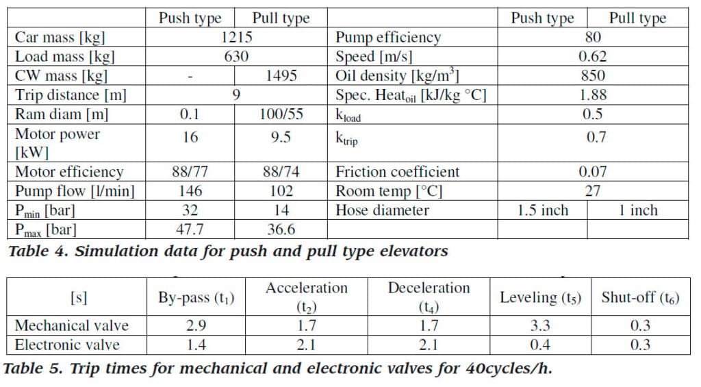
Simulations were performed at the highest (40 cycles/h) and moderate (20 cycles/h) working cycles using submersible and external motors. External coolers were not used and room temperature was assumed to be constant at 27°C. Using above data and applying aforementioned formulations, various heat balance curves were obtained, as shown in Figure 7. Figures 7 (a) to (c) were obtained with tank oil capacity of Q and (d) to (e) of 2Q.
It should be mentioned that the average trip times, given in Table 5 for mechanical valves, may be higher above 50°C, where longer by-pass and levelling times could be applicable due to the reduction in volumetric efficiency (increased leakage) of the pump and unavoidable cyclic temperature effect.
For high-usage elevators (z = 40), doubling tank oil volume decreased the balance temperature 8 – 10 percent for submersible units and 6.7 to 9 percent for external units. Whereas, for mid-usage elevators (z = 20), these percentages became 5.8 to 7.6 and 4.7 to 6.6 respectively. Assuming that 60% of air volume was blown onto the tank by the movement of the elevator car resulted in 2.3 to 3.7 percent drop in balance temperature when elevator usage was high (z: 40) otherwise, the percentage was below 1.2.
Power units with external motor could decrease the balance temperature 13 to 16 percent. Pull type elevators provided 17.3 to 21.5 percent decrease in balance temperature.
Electronic valves, which assured 6 to 10 percent drop in balance temperature, are advisable for high usage elevators. In general, for the pull type elevator the electronic valve could be used without a cooler whereas, the push type
elevator with submersible motor required a cooler or higher oil volumes.
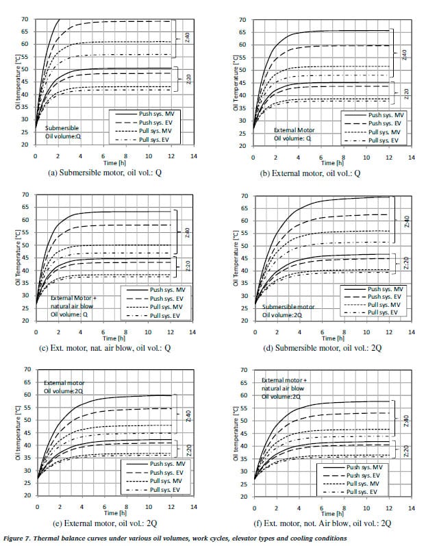
Mechanical valves are generally suitable for low usage. When the pull type elevator with external motor and/or 2Q oil capacity is used then the mechanical valve could also serve to elevators with middle usages.
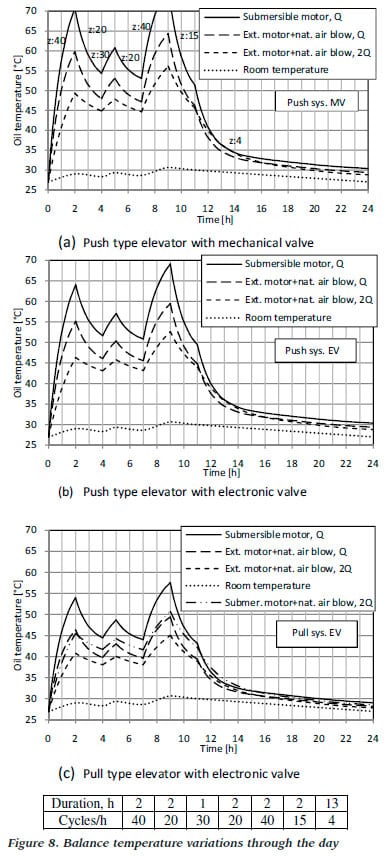
Since it is very rare that elevators are used at their maximum cycle capacity, it is more logical to evaluate the balance temperature according to a utilization scenario throughout the day. In Figures 8 (a) to (c) resulting balance temperatures of such a scenario is given with varying room temperature.
Figures 8 (a) to (c) illustrates that under the scenaric condition the push type elevator with mechanical valve could be used with the external motor, cooler and 2Q oil capacity (8-a). Swapping the mechanical valve with the electronic one may eliminate the use of cooler with the external motor (8-b). The pull type elevator, on the other hand, could be utilized with a submersible unit with the help of a cooler or with 2Q oil capacity (8-c). However, use of external motor, preferably with 2Q oil capacity provides the best solution.
6. CONCLUSIONS
It is felt that the best way to avoid heat related problems or at least to minimize them is to design heat-efficient hydraulic power units. Therefore, adequate importance should be given to heat balance evaluation to avoid undesirable thermal effects on the elevator system. Such an approach obviously takes the life-cycle, technological and environmental parameters into consideration.
High quality rides can be obtained by narrowing working oil temperature range. The most economical way of carrying the heat away is through natural dissipation without a cooler. When necessity of a cooler is not clearly justified, a low power fan blow over the tank should be considered.
Power units with the external motor decreased the balance temperature 13 to 16 percent. Pull type elevators with counterweight drastically lower motor power and pump flow rate. As a result of that, 21.5% decrease in balance temperature was obtainable.
Utilization of pull type power unit with electronic valve and external motor, preferably 2Q oil capacity could be safely used at higher working cycles without coolers.
If the choice is a push type elevator, mechanical valves serves very well for low-usages otherwise electronic valves should be preferred. However, when the pull type is used, mechanical valves can also be used with external motor units at mid-usages.
REFERENCES
Brenden, C., (2002). Insider secrets to hydraulics, Hydraulic supermarket, West Perth.
Celik, K. F. (2008). Design and control of electronic valves. Proceedings of Elevcon 2008, IAEE, pp. 34-45.
Celik, K. F. & Körbahti, B. (2006). Why hydraulic elevators are so popular? Part 2. Asansör Dünyasi, Vol.51, pp. 48-53.
Hehn, H. A., (1995). Fluid power troubleshooting, Dekker, New York, pp. 347.
Majumbar, S. R., (2003). Oil hydraulics systems, McGraw Hill, New York, pp. 318.
McRee, G. (2007). Measuring the heat from hydraulic lifts. Report for George Floth Consulting Engineers.,pp. 6-11.
Yeaple, F., (1996). Fluid power design handbook, Dekker, New York, pp. 37.
Get more of Elevator World. Sign up for our free e-newsletter.

