InterContinental Danang Sun Peninsula Resort, Danang City, Vietnam
Jan 1, 2013
Category 6: Inclined Elevators
submitted by Mark Galvin, Access Automation, Ltd.
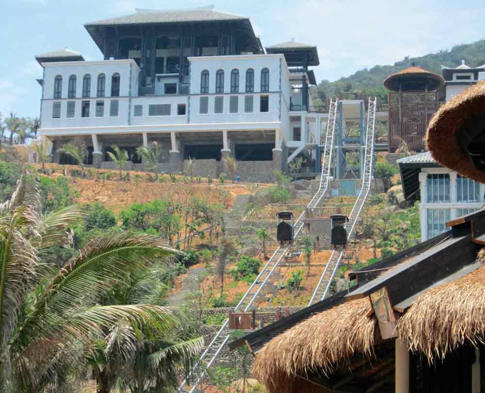
The InterContinental Danang Sun Peninsula Resort is located in an isolated cove a few kilometers north of Danang City, Vietnam. The resort comprises a large complex of beachfront villas, 192 rooms, conference facilities and restaurants built over a north- facing slope, which provides views of the private cove and the South China Sea.
The challenge for Access Automation, Ltd. was to design, manufacture and install an inclined-elevator system for guests and resort staff to access the steep topography. The solution involved developing two custom-designed, multi-gradient inclined elevators that run through the center of the resort. The two elevators are named the “Nam Trams.” Created by the architect, the name reflects how the installations were blended into the contemporary/Asian architecture that characterizes the resort.
Both the aesthetic and engineering challenges of the project were substantial. From a functional viewpoint, the elevators needed to run through the heart of the resort to provide convenient access and connection between the villas and facilities. Being such a central feature of the resort, the elevators needed to be designed to blend with the environment. Working closely with the architects, Bensley Design Studios, Access Automation designed the cars to look like traditional Vietnamese fishing boats gliding through the resort. The car’s exteriors are handcrafted rattan-skinned boats that sit unobtrusively in their surroundings. Embodied under the rattan skins are modern control systems and features that allow the cars to safely and smoothly negotiate the three gradients of the 130-m-long tracks.
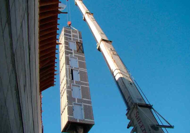
The project layout required the top section of the rail structure to be elevated 12 m above ground. This presented a challenge, because crane access was unavailable, and the structure needed to be robust enough to withstand wind speeds in excess of 200 kph. The marine environment, temperatures and monsoon rains also required demanding specifications. To meet the demands, Access Automation completely re-engineered several structural elements. The pair of 130-m-long multi-gradient rail structures needed to maintain a high level of geometric precision but had to be able to safely deflect, in a controlled manner, in typhoon winds and during thermal cycling. The tall rail sections under construction give an idea of the scale of the structural elements involved. To be able to install such a massive structure without a crane, a large zip-line was built.
Self-Leveling Technology
At the center of each inclined elevator is Access Automation’s self-leveling bogie system. It is a mechanical-based leveling system that uses rail geometry to keep the car level as it operates on different rail gradients. The rail gradients vary from 48° to 22°, with 15-m radius transition sections. The large radius bends and carefully calculated rates of change of curvature at the entry and exit of the bends allow the cars to negotiate the changes in gradient at the full design speed of 1.5 mps without any destabilizing accelerations imposed on the passengers. The use of high-speed, self-leveling cars was essential on this project to allow the developer to connect the required levels and meet the elevator capacity. The rail geometry incorporates both concave and convex bends. On the convex gradient changes, the towing rope drops into the sheave rollers. However, on the concave gradient changes, the rope needs to be captured to keep it parallel with the rail line. The mechanical design of this detail is complex, as there is minimal room to mount the sheaves between the floor of the car and the rail. The sheave assemblies are monitored by safety switches to check for correct rope engagement.
Structural Design of Rail and Foundations
The design of the rail structure also presented challenges. The top section of the rail is elevated 12 m above ground and must withstand 200-kph wind speeds. In addition, the thermal cycling between cold and wet weather and the height of summer temperatures means the rail structure can expand and contract by as much as 60 mm. Further complicating matters was the fact that crane access was not available on site, limiting the maximum weight of any component to 450 kg (the limit of the zip-line system). The first challenge of stabilizing the 12-m-tall foundations was achieved by connecting the east and west cable-car frames into a common structure with diagonal braces. Finite element analysis was used to optimize the weight of critical foundation components, and tower lengths were broken into bolt-together sections of appropriate weight. Considerable research was required to develop a movable rail joint to accommodate smooth, quiet and serviceable thermal expansion. The pairs of rail joints are all herringbone cut, so there is no perceivable bump as the wheels pass over the gap in the joins.
3D CAD
Crucial to the success of this project was the use of 3D computer-aided design (CAD) modeling, both in the initial marketing/concept presentation phase and manufacture. The methodology used for manufacture was to obtain accurate topographical data from the project surveyor. From this data, the detailed design was carried out using SolidWorks 3D design package to ensure the structure would fit on site. The CAD models are also used to generate the laser cutting files for the prefabricated rail-transition sections. Next, the rail structure was manufactured in New Zealand as a kit set that could be broken down to 5-m-long modules for sea freighting to Vietnam. These rail modules were bolted together on site over an eight-week construction period.
Range of Involvement
Access Automation was closely involved with various aspects of the elevator project over a limited timeframe. It made the initial site visit and worked with the client’s architect and engineer to develop the project layout and specification that met the resort’s needs. In addition, it provided rail and foundation structural designs, R&D and construction design of the mechanical parts, manufactured all electrical and mechanical elevator components, and installed and commissioned the equipment.
In many ways, the most interesting challenge of the project was turning the architect’s vision of the Vietnamese fishing boat into a safe and functional elevator cab. The dilemma was for the exterior of the car to have a rustic, hand-finished appearance, while not compromising passenger comfort or safety. The cars were fabricated in New Zealand using stainless-steel frames that form the boat shape. The car interiors are clad with embossed stainless-steel panels and feature modern controls and safety features. The connection between the boat and the supporting chassis below is via rubber pads to act as a final step to maintain ride smoothness.
Due to the complexity of the rope-management system around the various sheaves and bends, it was more practical to use a single rope with a high factor of safety. Even so, when the car is at the bottom, there is approximately 160 m of rope deployed. To prevent the cab level from creeping up or down as passengers enter or exit, an active control system is used to keep the car aligned with the deck level. A closed-loop control system is used on the motor inverter so subtle changes in motor/winch drum position are possible while the car is being loaded. Communication between the car and main control system is via a failsafe radio link.
Specifications
- Number of inclined elevator systems: Two
- Rail length (per elevator): 130 m
- Dual rails structure: Two off
- Rail gradients: Three (48°, 22.5° and 48°)
- Bogie system: Access Automation self leveling
- Design wind speed (structural): 56-mps ultimate design state
- Car speed: 1.5 mps
- Elevator capacity (per elevator): 300 people per hour
- Car maximum payload: 750 kg
- Number of landings per elevator: Four
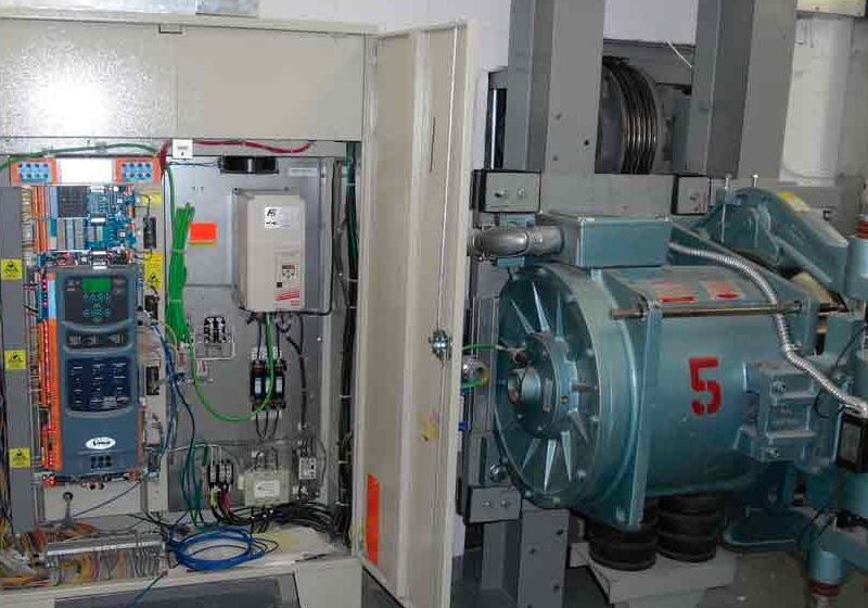
- Winch system: Drum winch with 30-kW motor and variable-speed drive
- Rope: 16 mm, 160 kN MBL
Credits
- Installer: Access Automation
- Hotel operator: InterContinental Danang Sun Peninsula
- Owner and developer: Sun Group, Vietnam
- Architect: Bensley Design Studios
Get more of Elevator World. Sign up for our free e-newsletter.

