King of the Hill
Oct 1, 2018

thyssenkrupp inclined elevators make life easier for commuters who use Spanish metro line.
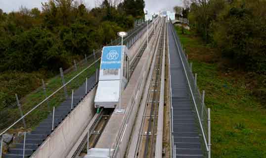
The Bilbao Metro Line 3 is a Spanish metropolitan railway line operated by Euskotren that serves about 71,000 people from various districts in the north of Bilbao and connects them with the municipality of Etxebarri. The line goes out in the open air in its final section, near the station of Kukullaga in the district of San Antonio de Etxebarri. The station, on its mezzanine level, connects with the neighborhood of San Antonio by two lifts inclined to the middle hillside through a walkway and access corridor under a national road, an arrangement that achieves its connection with the high district along a hillside of great slope. These two inclined elevators give a quick and comfortable access not only to the Line 3 Station and the future station of the tram, but also to the lower part of the municipality. The elevators were manufactured by thyssenkrupp Elevadores Manufacturing Spain, and the vertical transportation system contractor was thyssenkrupp Elevadores S.L.U. The promoter of the project was the Basque Government and Diputación Foral De Bizkaia; risk prevention was provided by CSP, Coordinación y Seguridad de Proyectos.
These elevators have three stops to make accessibility more effective. The lower one connects with the station at mezzanine level. The intermediate stop, on the hillside, gives accesses to a pedestrian path that connects with a medical center and school. The final stop connects with the highest area of San Antonio.
The location of the elevators took into account the layout of the accesses to the mezzanine of the station, as well as the urban environment and their operation. Their forms and coatings were designed to guarantee the functionality of the system, while maintaining the architectural aspect of the installation.
Project Details
Built with glass and stainless steel, the elevators have a panoramic front, a constant incline of 30°, center-opening side doors and capacity for 25 riders, with a maximum load of 1875 kg per cabin. The elevators travel a distance of 190 m, carrying riders up and down a height of 96 m. Traveling at a nominal speed of 2 mps, the elevators have the capacity to transport more than 780 people per hour. Each has three stops.
Because these inclined elevators operate outdoors, all structural elements were designed to be protected from the weather. They can be classified within the category of electric and outdoor equipment suited for public use and, within this category, are specifically designed for use by people with reduced mobility, in accordance with EN 81-70.
This facility is designed for reliability and constant availability, even in adverse weather conditions. The elevators are designed to provide passengers with a high level of comfort, safety and ease of use. Acceleration and deceleration are smooth, to ensure passenger stability even in case of an emergency stop. The installation includes lateral evacuation ladders along the whole route (except in the area of the tunnel under the road, where the evacuation is by central stairs). Other safety features include evacuation lighting and stretcher accessibility.
Installation
The coordination of the installation of the evacuation ladders in parallel with the assembly of the inclined elevators was a great challenge in terms of logistics and safety, given the outdoor working conditions and the project’s location on a steep hillside. The most critical tasks, including coordination of health and safety efforts, were planned in detail and revised in daily meetings among the installation company, client and Ertzaintza (Basque regional police), who were needed to temporarily close off the national road that runs above the route of the elevators.
thyssenkrupp Elevator’s Project Management and Special Assemblies departments coordinated the project from the beginning to ensure compliance with the highest quality standards that a project of this size requires.
The inclined elevators run through an enclosure consisting of a concrete double open pit, each side with 2.15 m of width and 1.7 m of depth free. The cabin moves on a path composed of metal beams and a tread band fixed on the concrete support.
Both the cabin frame guides and the counterweight guides are located along the gap, have an “H” section and accommodate the displacement of the counterweight. A calibrated T-type guide is available, forming the base for wedging produced by the safety gear.
The maneuver cable is housed in an articulated cable housing that is resistant to mineral oils and saltwater. The electrical cabinet is near the engine in the engine room at the top of the route, below the upper loading level, providing easy access for authorized personnel through an access door. Shock absorbers for the cabin and counterweight are in the pit, as is the limiter tensioner, which is easily accessed by a trapdoor. The pit has sufficient space under the frame for maintenance.
The frame holds the cabin and counterweight and is built with galvanized and painted laminated profiles. It moves along the guides by means of wheels. It has a wedge shape, ensuring that the cabin floor position remains absolutely horizontal, and is formed by main beams on which sit the rest of the structure, as well as the exterior decorative panels. The structure houses a speed limiter, progressive emergency-fall system and connection supports for the maneuvering rope.
It has a direct suspension, in which the speed of the tractor pulley matches the cabin speed. The suspension is 1:1, and the cables used for the counterweight and cabin structure suspension are made of galvanized steel to protect them from the elements, while offering a high resistance and safety coefficient.
Assembly and Maintenance
Inclined elevators have very different construction and operating characteristics than vertical lifts, and have completely different assembly and maintenance procedures. The development of working conditions must account for an outdoor and sloping environment, making it necessary to intensify safety conditions and establish security protocols adapted to the requirements of the project. Once this was done for this project, the procedures were:
- Execution of the civil work of the elevator shafts, carried out by owner Euskal Trenbide Sarea (ETS). The lifeline was then installed by a company specialized in work on steep inclinations. This initial phase included a topographic study that formed the basis for the detailed design of the inclined elevators.
- The placement of rods and fixing plates for the structure was done next. Using the lifeline, numerous holes were made in the concrete, and the supports for the beams were installed. This was a time-consuming process, because the dangers of material falls restricted the number of technicians who could work within the shaft. This stage also coincided with summer’s high temperatures, which further complicated the progress.
- Materials collection: the enormous travel distance of the elevators meant the assembly materials had to be deployed to each of the three stops to allow access by cranes at each point.
- Placement of the tread structure: this part of the assembly involved the temporary blocking of a lane of the adjacent national highway to allow access for a large-capacity crane.
Coordination in this phase was key to optimizing assembly time.
- Installation of elevator elements in engine room and pit: the main elements of the lift were installed in this stage. This work occurred during periods of heavy rain, forcing the constant use of pumps to evacuate the water.
- Installation of slings and cabins: These components were placed directly with the help of cranes. The cabins arrived fully assembled and inspected from the factory to guarantee the highest quality. This milestone was mentioned in many local media outlets, reflecting the community’s great enthusiasm for the project.
- Electrical installation and commissioning: this phase completed the assembly of the lifts and included a strict test protocol, closely followed by the quality department to ensure user safety.
- Installation of evacuation ladders: vegetation was cleared from both sides of the inclined elevators’ shafts to create room for the evacuation ladders. Individual modules of the ladders were designed in detail and transported in 6-m-long pieces to the worksite, where they were installed one by one. Large-capacity cranes were again needed for this stage.
- Installation of lateral closing for the evacuation stairs and nonskid treatment of the steps: to prevent people from accessing the elevator spaces, enclosures were installed around the entire perimeter. These enclosures include rails to facilitate the evacuation of users in case of emergency. An anti-slip paint was applied at the end of the mounting on the steps to avoid possible skids caused by rain or moisture.
The opening event for the inclined elevators coincided with the inauguration of the entire Line 3 of the Bilbao Metro, a ceremony that attracted heavy coverage by the national media. The event was chaired by representatives of ETS, Euskotren and the Basque Government, including Lehendakari (President) Iñigo Urkullu.
Your author served as project manager for the Etxebarri inclined elevator project, one of a number of technically difficult projects thyssenkrupp Elevadores Spain has undertaken in recent years, such as the Palacio Marqués de Salamanca and modernizations in the Adolfo Suárez Madrid Barajas airport and the Castellana 77 tower. Assembly chief was Antonio López Rayo, who has more than 25 years with thyssenkrupp, and has worked on projects in Spain, Portugal, the U.A.E. and South Africa.
Get more of Elevator World. Sign up for our free e-newsletter.


