Applications in elevator systems for the popular LonTalk standard are discussed.
Compatibility, interoperability, interchangeability, and open and standard protocols have been the hottest terminologies in the building-automation industry over the past three decades. Traditionally, protocols used by elevator supervisory controllers have been proprietary in nature, but there have been more recent developments in various standards. In Part 1 of this article, the science of open protocols is discussed, followed by a quick review on different open protocols used in building automation. One popular standard, LonTalk, with applications in elevator systems, will be discussed in detail.
What Are Communication Protocols?
A computer network, wired or wireless, is defined as a group of computers and other devices connected together to exchange information and share resources. One approach for organizing networks is called “client/server,” where one computer serves the storage and processing needs of all the other nodes (devices), called “clients,” on the network. Another approach is called “peer-to-peer computing,” in which every computer or device on the network can act both as a client or server. “Network topology” refers to the layout of computers on a network. There are three common topologies: star, ring and bus. In building automation, devices are often computers by themselves.
Humans use languages to communicate with each other; networked computers exchange data based on standard rules called “protocols.” Each message transmitted by a networked computer has an exact meaning with an intention to stimulate a response from the receiver. Hence, the protocol must define the syntax, semantics, synchronization of communication and others. As computers are not as clever and flexible as humans, protocol must be standardized. An analogy is that protocol for communication is similar to programming languages for computation.
There are various features of a protocol, including but not limited to data format, address format, address mapping between schemes, routing, detection of errors due to transmission, acknowledgement of correct messages, timeouts and retries, direction of information flow, sequence control and flow control.
International Standard on Networking
The Open Systems Interconnection (OSI) model by the International Organization for Standardization (ISO) provides a framework for both designing networking systems and explaining how they work. This model is the only internationally accepted framework of standards for communication between different systems made by different manufacturers. The goal is to create an “open systems” networking environment, in which any vendor’s computer or microprocessor system, connected to any network, can freely share data with any other computer system on that network or a linked one. Here, “open systems” provide such features as interoperability, portability and open software standards. Any vendor or manufacturer has the right to adopt an open system onto its device.
Most of the dominant communications protocols used today comply with this OSI model. It should be borne in mind that OSI is only a model, however — a framework but not a protocol. That means that even though two products may fully comply with the OSI model, they may not be able to freely communicate with each other, unless some agreements have been made during the design stage.
The model consists of seven layers. Each layer has specific functions and provides services for the layer immediately above it. Each time a data packet is received by the hardware, every layer processes the packet and submits it to the layer above. Layers 7-4 deal with end-to-end communications between the message source and the message destination, while layers 3-1 deal with network access (Table 1).

Layer 1 provides the most basic connectivity in terms of the physical media, which could be copper electrical wire, or radio-signal or fiber-optic cable. Devices like repeaters and hubs operate on this layer. Layer 2 is concerned with procedures and protocols for operating the communications lines, responsible for logical link control, media-access control, hardware addressing, error detection and handling. Layer 3 determines how data is transferred between computers by addressing routing within and between individual networks. Routers, which operate on this layer, receive a packet, analyze the destination address and route it. Layer 4 defines the rules for information exchange and manages end-to-end delivery of information within and between networks. Layer 5 is concerned with dialogue management, establishing and managing software process sessions. A device can simultaneously communicate with many other devices by assigning each connection its own session. Layer 6 provides a transparent communications service by masking the differences of varying data formats between dissimilar systems. It could be regarded as a translator between different types of data representation. It also encodes and deciphers encryption. Layer 7 contains functions for particular applications services, such as file transfer, remote file access, virtual terminals, etc.
Not all open protocols are implemented with all seven layers, and very often layers are melted together or collapsed.
Commonly Used Building-Automation Open Communication Protocols
There are many open communication protocols popularly adopted in building automation, such as X10, Modbus, C-Bus, digital addressable lighting interface (DALI), CANbus, ZigBee, TCP/IP, Open Building Information Xchange (oBIX), Konnex, LonWorks and BACnet. Besides the last two (which will be discussed in more detail in parts one and two of this series, respectively), the others will only be briefly introduced.
X10, developed in 1975, is a classical protocol for communication between electronic devices used mainly at home. Signals are injected into the power line as 120-kHz bursts, feeding an individual device during the zero-crossing points of the voltage waveform. However, only one bit is transmitted at each zero crossing, making this a very low-speed protocol. However, it is good enough for turning lamps on and off, or, at most, dimming them. Wireless X10 devices have since become available.

Modbus has its roots in the late 1970s. In 1979, programmable-logic-controller manufacturer Modicon published the Modbus communication interface for a multidrop network based on a master/client architecture. (A multidrop bus has all components connected to the same circuit, and a process of arbitration determines which device can send information.) The physical layer of the Modbus interface is flexible. It was originally on RS-232 but later on RS-485 to allow longer distances, higher speeds and the possibility of a true multidrop network. Modbus is often used to connect a supervisory computer with a remote terminal unit in supervisory-control and data-acquisition systems. Every Modbus message has the same structure (Table 2), which is rather generic across different control protocols used in building and home automation. Modbus was applied in elevator systems for sensing floor, car and door switches,[1] detecting car position optically, indicating floors and interfacing variable-voltage, variable-frequency drives. However, objects, features and functions of elevator systems are not specified by Modbus. Therefore, the application is still proprietary.
C-Bus, originally developed by Clipsal of Australia, is mainly for home automation — lighting control, in particular. Different from X-10 (which operates on a power line), C-Bus needs a dedicated extra-low-voltage (only up to 36 VDC) unshielded twisted-pair (such as category-5) cable, and its effective length is much longer than that of X-10, up to 1 km. Wireless C-Bus devices are also available.
DALI is another well-known control network. In the past, electronic ballasts and dimmers for lamps were controlled by a 0-10-VDC signal. With DALI, IEC 60929 (old version) or IEC 62386 (current version), a controller can monitor and control every lighting device on the network by means of a bidirectional data exchange. Group and scene broadcast messages are available to simultaneously address several devices at the same time, up to 64 in a standalone network. A dedicated bus with a fixed data transfer rate of 1.2 kbps is required.
The Controller Area Network (CAN) protocol is an ISO-defined standard (ISO 11898) for serial data communication at bitrates up to 1 Mbps. It was initially developed for the automotive industry but has become a popular bus in industrial automation. It is a two-wire, half-duplex (communication is bidirectional but unidirectional at any time), high-speed network system well suited for high-speed applications using short messages. The CAN protocol defines the first two layers of the OSI model, and there are four different message types (or frames) on a CANbus: data, remote, error and overload. Of course, the mostly common messages found on a CANbus are of the data-frame type. CANbus was applied in elevator control to deal with dispatching and energy savings.[2] But, again, objects, features and functions of elevator systems are not openly specified by CAN; the application is still proprietary.
As wireless control networks are in demand because of the popularity of Wi-Fi (IEEE 802.11 family of standards), a technology based on IEEE 802.15, called ZigBee, was developed in 1998. Standardized in 2003, it uses small and low-power digital radios. ZigBee devices can transmit data over long distances by passing it through intermediate devices, thus creating a mesh network without a centralized control or high-power transmitter/receiver. Now, ZigBee, with a standard data rate of 250 kbps, has been implemented in building-automation devices, mainly sensors, which can be freely placed in the room, because they require only a low data rate but have a long battery life and secure networking. Another wireless technology, Bluetooth, is mainly for a personal-area network, not suitable for building automation.
TCP/IP, perhaps the most well-known protocol in the world, actually refers to three types of protocols: Transmission Control Protocol (TCP), Internet Protocol (IP) and User Datagram Protocol (UDP). The U.S. Advanced Research Project Agency developed the first version of TCP in 1973. The first formal standard, version 4 (IPv4), was created in 1980. The TCP/IP model uses four layers, merged from the seven-layered OSI. They are the network-access layer (OSI physical and data-link layers), Internet layer (OSI network layer), transport layer (OSI transport layer) and application layer (OSI session, presentation and application layers).
IP is responsible for interconnecting different local-area-network technologies, creating a virtual network that allows all devices to communicate with each other as if they were on the same network. In IPv4, the IP address is a 32-bit binary number, while IP version 6 (IPv6) uses a 128-bit address (eight groups of 16 bits each). There are two versions of transport-layer services: UDP, an unreliable but efficient and fast transport protocol, and the TCP, a full-featured, connection-oriented transport protocol with flow control, and acknowledged transmission and retransmission mechanisms. TCP guarantees reliable and in-order delivery of data from sender to receiver. Unlike TCP, UDP supports packet broadcast (sending to all on a local network) and multicasting (sending to all subscribers). Common network applications that use UDP include the Domain Name System and such streaming media applications as Voice Over IP. Though unpopular, some building-automation devices are now implemented on TCP/IP.
oBIX, almost completed but still under development, is an industry-wide initiative to define Extensible Markup Language (XML), which is both human and machine readable, versus the commonly used HyperText Markup Language (HTML). XML is a web-services-based mechanism for building-control systems. The purpose is to define a standard web-services protocol to enable communications between building mechanical and electrical systems, and enterprise applications at a higher level. This protocol will enable facilities and their operations to be managed as full participants in knowledge-based businesses.
The three most popular and widely accepted open protocols for building automation may be Konnex, LonTalk and BACnet. In the 1990s in Europe, there were three popular network technologies: Batibus, European Installation Bus (EIB) and European Home System (EHS). In the late 1990s, they merged to form the Konnex Association, an organization that represents an open, royalty-free, platform-independent standard for home and building control, approved as both a European (EN 50090 and EN 13321-1) and worldwide standard (ISO/IEC 14543). The Konnex protocol uses only five of seven OSI layers, excluding the session and presentation layers. Major components of a Konnex network are Bus Interface Modules and Bus Coupling Units.
LonWorks
The LonWorks system, developed by Echelon Corp. of San Jose, California, is a networked automation and control solution for markets including the building, industrial, transportation and home ones. The protocol itself is called LonTalk and is certified as national and international standards ANSI/CEA 709.1, IEEE 1473-L, EN 14908 and ISO/IEC 14908-1.
According to Motorola’s LonWorks Technology Device Data Book:
“LonWorks technology is a complete platform for implementing control network systems. These networks consist of intelligent devices or nodes that interact with their environment and communicate with one another over a variety of communications media using a common, message-based control protocol.”[3]
In a LonWorks network, no central control or master/slave architecture is needed. Intelligent control devices, called nodes, communicate with one another using the common LonTalk protocol. Each node contains embedded intelligence that implements the protocol and performs control functions. In addition, each node includes a physical interface (transceiver) that couples the node microcontroller (neuron chip) with the communication medium. Each neuron chip has a unique 48-bit neuron identifier (ID) burned into the hardware, which is a special feature of LonWorks. A device can broadcast this ID across the network to let the network-management tool assign a logical address to commission the device.
LonWorks supports multiple communication media, such as twisted pair, power line, coaxial, infrared, optical fiber and radio frequency, and LonTalk can be channeled through TCP/IP[4] with the help of a device. The most fundamental medium involves the use of 16-AWG unshielded twisted-pair cables with a data rate of 78.1 kbps, either in free or bus topology. The highest rate can reach 1.25 Mbps (still on twisted pairs) but in bus topology only.

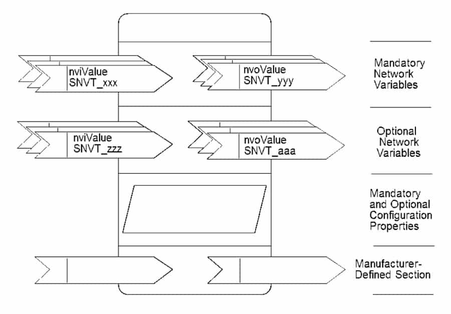
The key elements of LonWorks are network variables (NVs) and configuration properties (CPs), together forming functional blocks (Figure 1). A network variable could be any datum (temperature, a switch value, an actuator position setting, etc.) a particular device-application program expects to get from other devices on the network (an input NV) or expects to make available to other devices on the network (an output NV). NVs are the virtual (fictitious) connections between devices over the network. CPs are like virtual dual in-line package switches on hardware for the user to select particular modes of device operation. They provide standards for documentation and for network message formats used to configure the operation of a device or functional block. If different vendors adopt their own NVs and CPs, devices cannot be interoperable. So, a governing body, LonMark International, acts as the police to enforce standards, and promote and advance the business of efficient and effective integration of open, multivendor control systems utilizing ISO 14908-1 and related standards.
LonMark publishes standard network variable types (SNVTs), standard configuration property types, standard functional profile templates, standard enumeration types and standard program IDs, and certifies products. Only network variables of the same type of two devices can be linked together for interoperation. Therefore, it is of the utmost importance that devices are manufactured to standard functional profiles by vendors for full interoperability. A predefined structure of a functional block for a particular type of device, defining all mandatory network inputs and outputs of a specific function and such configuration properties as rates, limits and defaults, is called a standard functional profile. Having said that, a vendor is still allowed to add optional network inputs/outputs and configuration properties to a device beyond LonMark requirements, thus designing its own control algorithms and functional software within the device.

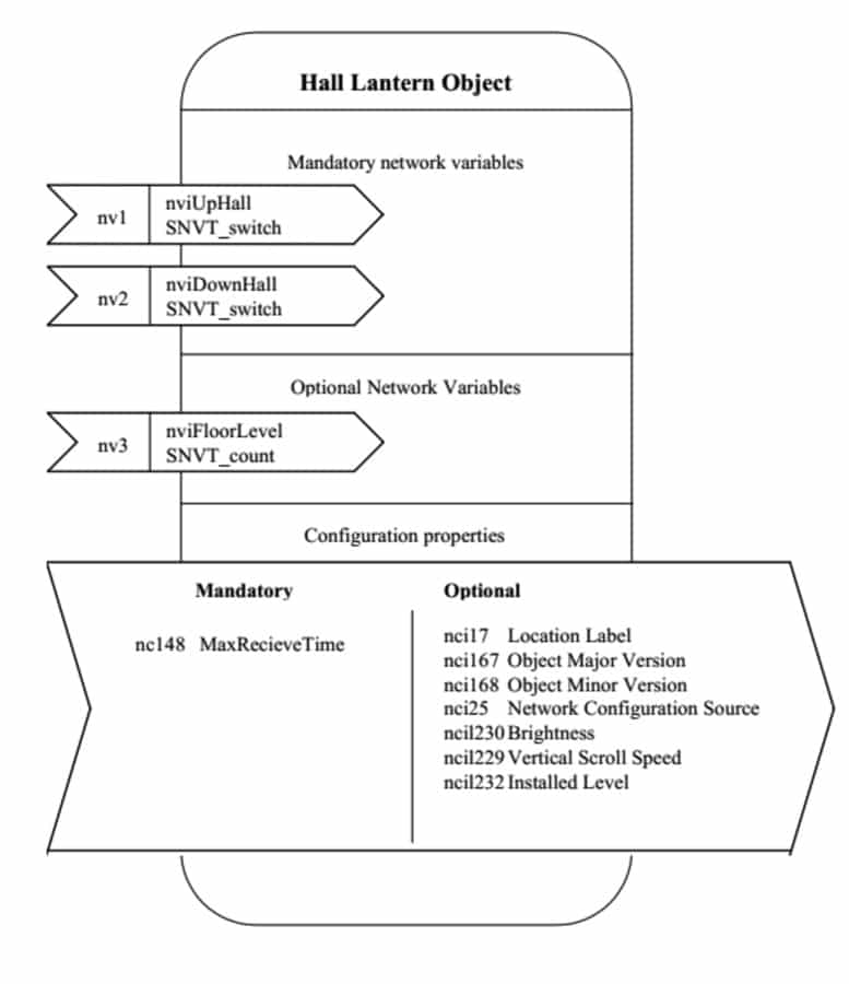
For applications in elevator systems, the following standard functional profiles are available but not limited to:
- Elevator access controller
- Elevator indicator
- Elevator position indicator and message display
- Elevator hall lantern (Figure 2)
- Elevator arrival gong
- Elevator car-direction lantern
- Vertical/conveyor transportation-system interfaces
- Elevator fire-systems port
- Vertical/conveyor transportation communication devices
- Elevator voice announcer
- Existing SNVTs are often employed within these functional profiles. For example:
- Floor name is given by “SNVT_str_asc,” which is a character string up to 30 characters.
- Directions of travel (“UpCar” and “DownCar”) are given by “SNVT_switch,” which is mainly a Boolean function indicating on and off but with grey levels.
- Car position is given by SNVT_count, which is an “unsigned long” of 2 bytes in size with a minimum value of 0 and maximum value of 65536.
Other SNVTs, such as “SNVT_motor_state,” “SNVT_power,” “SNVT_amp” and “SNVT_elec_kwh,” can also be used in an elevator system.
Conclusion
The science of open protocols has been discussed, followed by a quick review on different open protocols used in building automation. Though ModBus and CANbus have been employed in elevator systems, they are still considered proprietary, because the objects and messages for communication of different manufacturers are not open to the general public. One popular standard, LonTalk, was discussed in more detail. Standard network variable types and standard function profiles for use in elevator systems have been highlighted. They are open protocols, as different manufacturers can integrate them in their control systems. In Part 2 of this article, another popular standard, BACnet, will be discussed, as your author has been involved in the development of some specific objects for elevators.
References
[1] Shabarinath, B.B. and Gaur, N. “Modbus Communication in Microcontroller Based Elevator Controller,” Proc. 2013 Int. Conf. on Control, Automation, Robotics and Embedded Systems, IEEE, Jabalpur, India, Dec. 2013.
[2] Jian Chu and Qing Lu. “Research on Elevator Intelligent-Card Control System Based on CAN Bus,” Prof. 2012 Int. Conf. on Systems and Informatics, IEEE, Yantai, China, May 2012.
[3] Tiersch, Friedber. LonWorks Technology: An Introduction, -2. Aufl. –Erfurt: Desotron-Verl.-Ges, 2002.
[4] Shahnasser, H. and Wang, Q. “Controlling Industrial Devices over TCP/IP by Using LonWorks,” Proc. Global Telecommunications Conference, Sydney, 1988.
Get more of Elevator World. Sign up for our free e-newsletter.


