Revisiting History
Dec 1, 2021

In this Readers’ Platform, your author reflects on a lift modernization undertaken 30 years ago.
by Colin Craney
In a paper for ELEVATOR WORLD UK a few years ago, I looked at the restoration of a historic lift. I have since revisited the lift (which is still in service 30 years after the restoration), and I reflect upon how we approached the restoration back then.
The site, Victoria Square House, was the former head post office in Birmingham, and was to be redeveloped to include a modern office structure. The post office hall formed the front section of the building, which was constructed in 1891 to a design by architect Sir Henry Tanner and which was to be retained with the new development abutting its rear elevation. The architect nicknamed the retained building “the Chateau,” reflecting its French Renaissance architectural style (Image 1).
Its refurbishment was a key condition of planning approval for the development. The post office contained the postmaster’s lift, which was scheduled to be replaced with a modern, six-person lift. The historical architect viewed the lift and surrounding stairwell and determined this should be retained and restored. The brief was basic: anything could be changed so long as it did not encroach upon the visual aesthetic of the lift and stairwell. The lift had not functioned for many years and was equipped with a DC mains electrical supply motor (Image 2) and collapsible gates, so this appeared to be a tall order. The exact date of installation is uncertain, but was most likely in the 1920s or early 1930s.
The lift had a 1350-lb (600 kg), nine-person capacity and originally served five landings traveling a distance of 17.5 m at 0.7 m/s. A geared machine with a DC drive motor was located in a motor room directly below the lift pit (Image 3). The lift shaft was circular with a six-sided lift car (Image 4). Whilst the machine is roped for four-rope traction, only two ropes of 13-mm diameter were actually provided. These were looped back at the lift car top rope termination with both ends terminated at the counterweight, providing for four-rope traction at the sheave grooves (Image 5). Two overhead diverters were located at the top of the lift shaft, diverting the ropes from the car and counterweight to the lift machine (Image 6).
The lift car and counterweight are the original equipment and, unusually for an installation of this age, operate in “T” profile guide rails. The car has the original serrated cam safety gear, with a Dewhurst overspeed governor located at the top of the lift shaft replacing the original Dewhurst governor. As well as providing for the diversion of the two suspension ropes, the car top rope anchorage included a device to equalize tensions in the two ropes and was such that an excessively unequal tension or failure of either rope caused the safety gears, both car and counterweight, to engage. The car was attendant-controlled and had two manually operated collapsible car gates. The landing gates were of similar design. The gates were interlocked with early Dewhurst design interlocks.
The counterweight is the original cast-iron construction and operates within “T” profile guide rails and was equipped with a rope equalization/tension operated by serrated cam instantaneous safety gear.
The shaft was open, with a 2-m-high steel mesh screen at the landings and in the interior of the circular stairwell (Image 7). The building was to be office accommodations, and the lift was to provide passenger service to a board room, with no public access. This assisted in relation to the retention of the collapsible lift car and landing gates, although it was necessary to replace the original gates which incorporated excessive gaps. New mid-bar design collapsible gates of similar design and construction, but with reduced gaps, were installed (Image 8).
The survey of the installation proceeded, and we determined that the lift car and counterweight, lift machine gear and guide rails could be retained and modified to provide further service. The design was to meet, so far as reasonably practicable, the standards prevailing at the time, BS5655-1:1986 (EN81-1:1985) and BS5655-11:1989.
In negotiations with the local authority inspector, it was agreed that the mid-bar car and landing gate design could be retained and that the lift car and counterweight instantaneous safety gears could be inspected and tested and, if satisfactory, could also be retained. Despite protests of the historical architect, the inspector insisted upon a full height steel mesh enclosure for the lift shaft (Image 8).
The lift machine was overhauled with a new AC drive motor and what was, at the time, a modern Dewhurst brake (Image 9). A microprocessor controller was installed. Cost restrictions prohibited the inclusion of a variable-frequency drive, and the drive was to be two-speed AC. Car and counterweight safety gears were retained with overspeed governor operation for the car and broken rope operation for the counterweight. The rope anchorages at both car and counterweight were modified to accommodate rope suspension. New polymer buffers replaced the original volute springs. New mid-bar gates, complete with new interlocks, were provided. The car was refurbished to its original condition with new operating fixtures sympathetic to the original design (Image 10).
The architect required the attendant control handle and lever emergency stop handle be retained, albeit nonfunctional (Image 11). Originally, operation of the emergency stop handle whilst the lift was in motion locked a small-diameter wire rope which was connected to a mechanical trip of the main power supply isolator to open the lift drive circuits. Whilst the handle and attendant control features were retained for aesthetic purposes, modern automatic control and emergency stop switches were added.
The car had two entrances located side by side in two of its six sides. One of these became redundant, as access to a mezzanine floor was no longer required and the car enclosure was modified (Image 12). A car refurbishment contractor was engaged to remove the redundant car entrance and reinstate the sidewall. An additional emergency-stop switch was installed, as the redundant car entrance had been directly adjacent to the car operating panel that incorporated the original emergency stop switch. (The British Standard relating to the use of collapsible car gates required an emergency stop switch be positioned within easy reach of the car gate). The architect would not consider lift shaft fascias, so a solenoid released car gate interlock prevented opening of the car gate between floors.
Overall, it was a successful project. On reflection, what would we do differently today? Well, for a start, a modern EN 81-20-compliant brake, together with unintended car movement protection in the controller and a governor-operated counterweight safety (rather than the broken rope operation that was compliant at the time), could be installed.
“Overall, the lift is still in good condition and in service almost 100 years after the original install and more than 30 years after the restoration.”
Current condition is good. There is a minor oil leak from the machine gearbox, but otherwise, it is fine. The controller is dated, but also fine. We might now consider an infra-red screen across the car entrance to detect the intrusion of foreign objects and mitigate entrapment risk. We might also consider:
- A variable-voltage/variable-frequency drive, rather than the cost-reduced two-speed drive
- Fixtures retained to meet the architectural requirement, but with EN 81-70 buttons and signals together with an emergency autodialer
- A guard for the governor tension frame and a modern pit ladder design
- Paint décor for the machine room (another concession to the quantity surveyor’s cost plan)
- Improved access to the overhead pulleys
- Mechanical retaining protection to mitigate the risk of overhead pulley shaft failure
Overall, the lift is still in good condition and in service almost 100 years after the original install and more than 30 years after the restoration. In this sense, the restoration — and additional cost incurred at the time — seems worthwhile. And, the lift could readily be updated to provide a further 30 years of service.
I have had the good fortune to be involved in a number of projects involving the restoration of historic lifts. Whilst this one presented its particular challenges, another involved a 1908 vintage electric drum-drive passenger lift with travel distance in excess of 87 m, which may feature in a future paper.
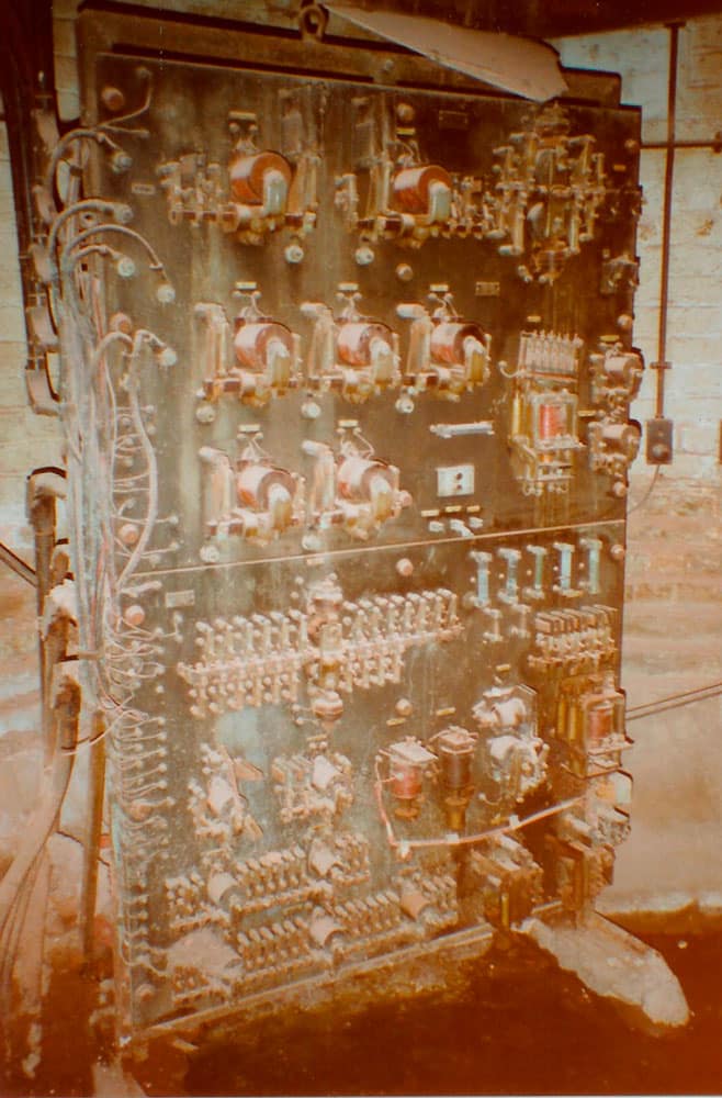
2. Original DC electrical supply controller 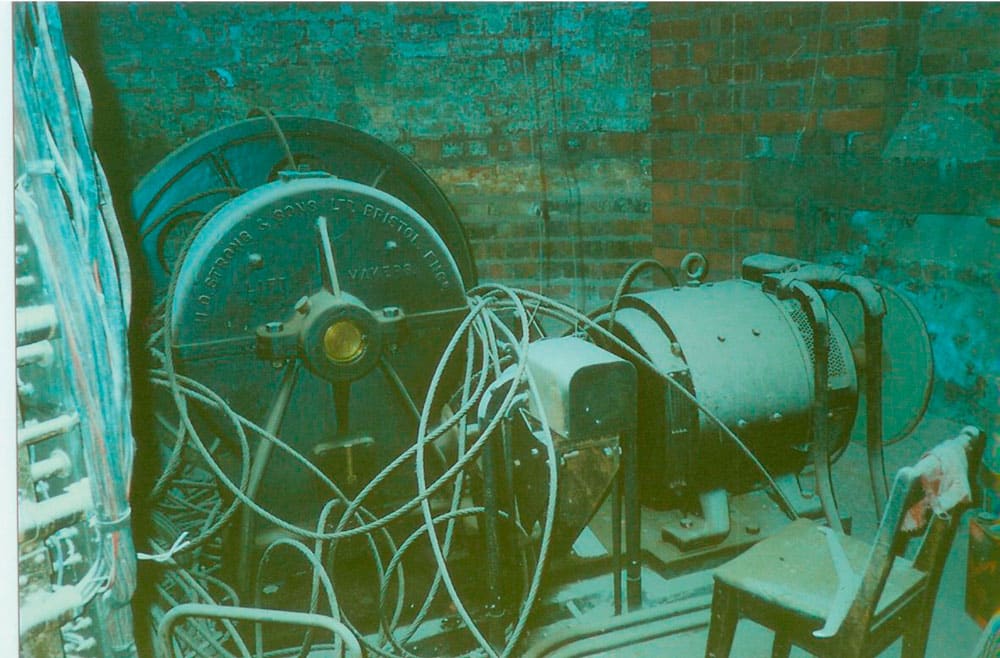
3. Original lift machine with DC motor 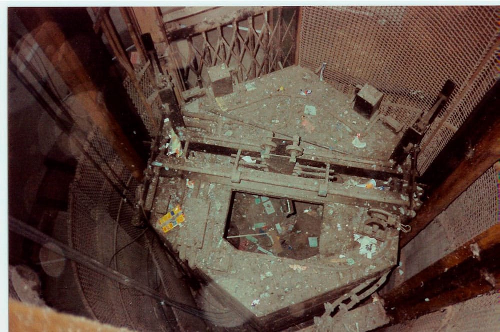
4. Six-sided car in circular shaft 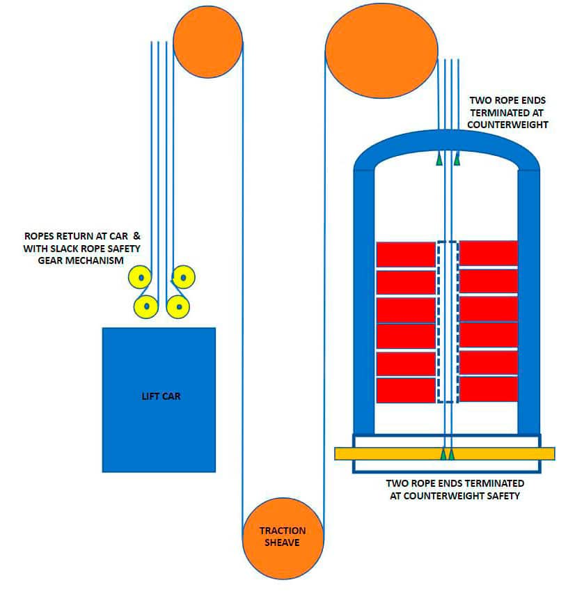
5. Schematic representation of the original two-rope suspension to provide four-rope traction design 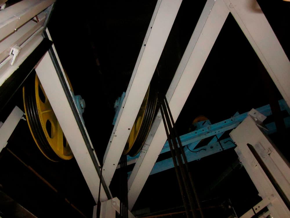
6. Restored overhead pulleys and new car overspeed governor 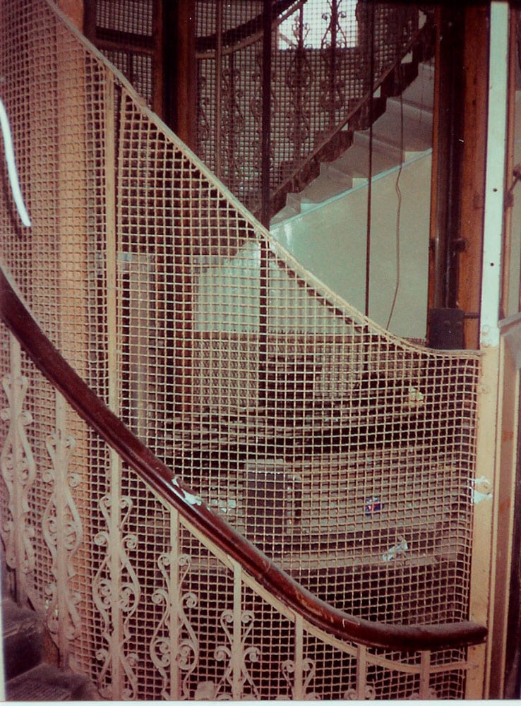
7. Original shaft enclosure 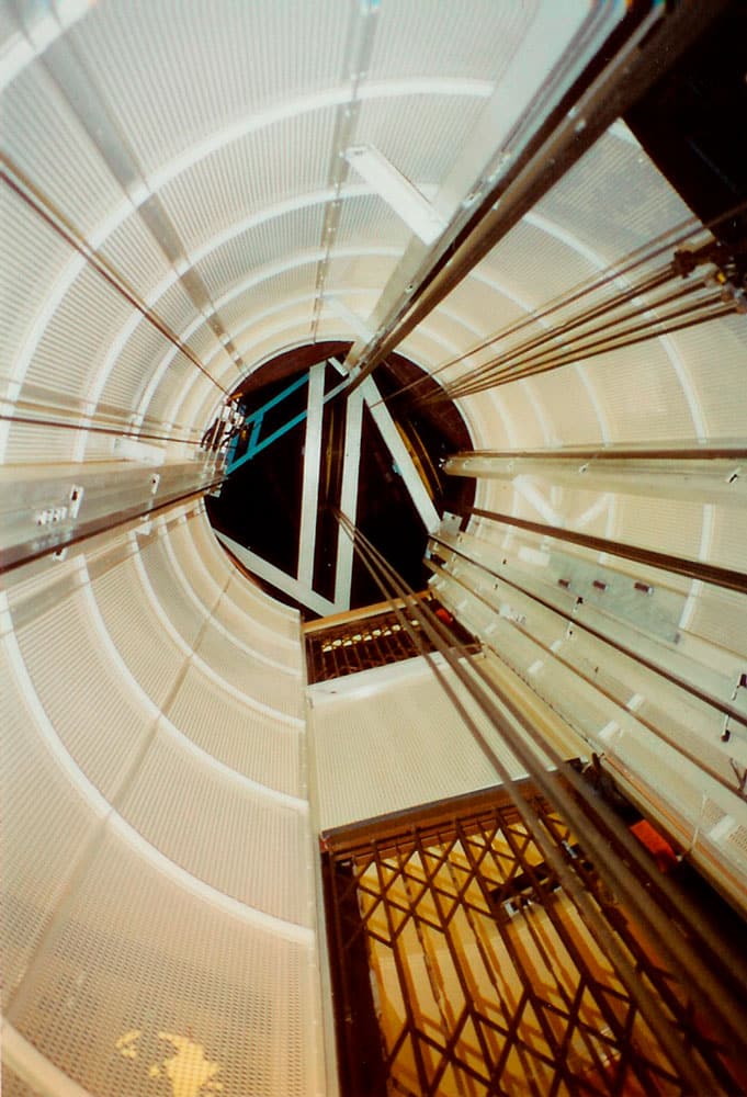
8. New shaft enclosure and mid-bar gates 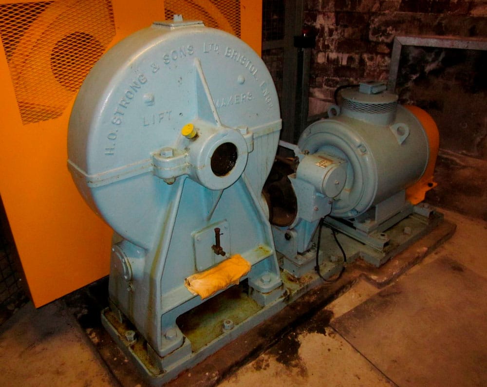
9. Restored lift machine still in good condition 30-plus years after restoration 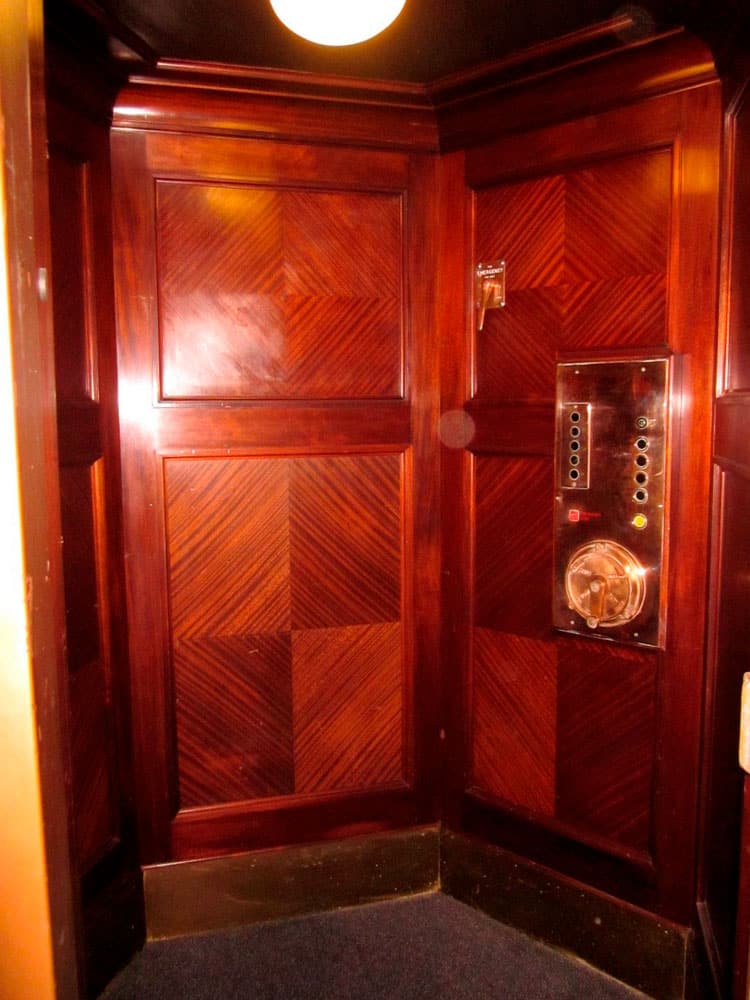
10. Restored lift car with retained lever emergency stop and attendant control 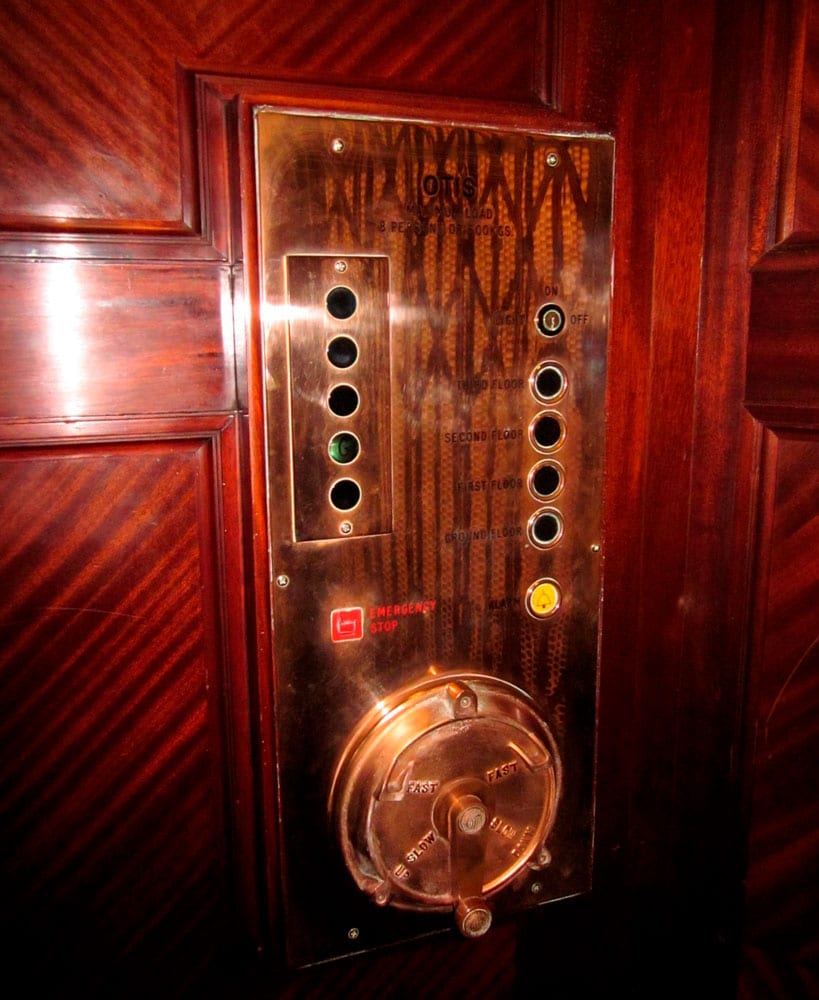
11. Retained car panel and attendant control 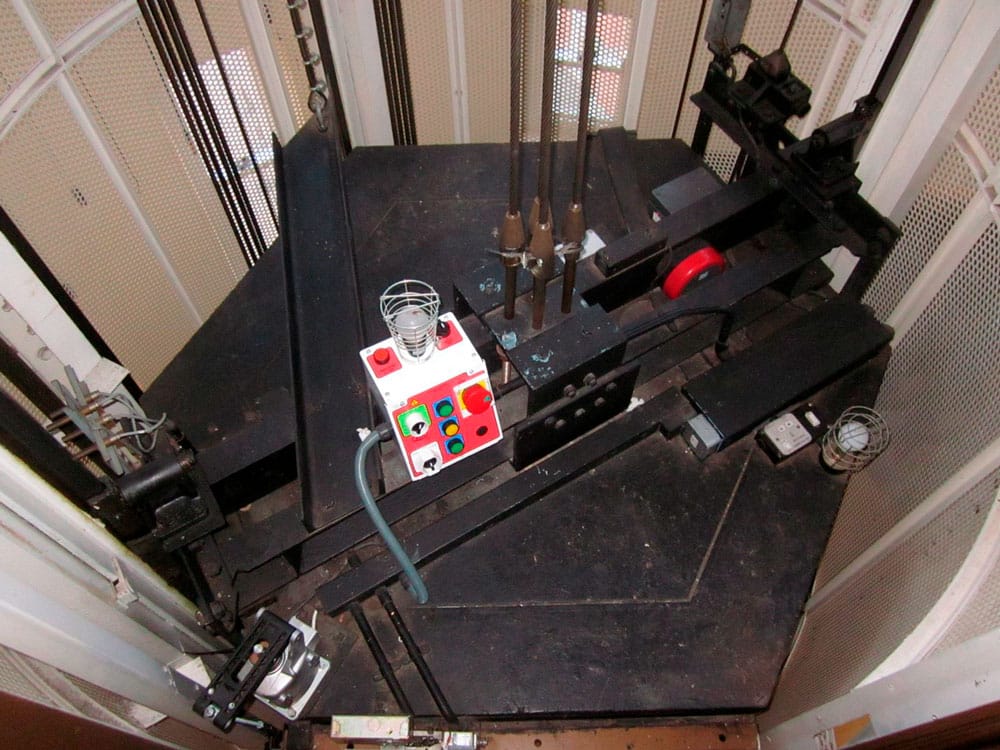
12. Refurbished lift car for single car entrance and new rope termination 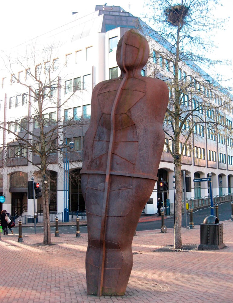
13. “Iron:Man” by Sir Antony Gormley (in original position prior to temporary removal)
Get more of Elevator World. Sign up for our free e-newsletter.


