The Application of Electromechanical Spring-Set Brakes in MRL Machines
Jan 1, 2011
“This article discusses some of the basic components and operation of DC electromagnetic spring-applied brakes.”
by Jonathan Bullick
Value: 1 contact hour (0.1 CEU)
This article is part of ELEVATOR WORLD’s Continuing Education program. Elevator-industry personnel required to obtain continuing-education credits can receive one hour of credit by reading the article and completing the assessment examination questions found on page 121. For this article and more continuing-education opportunities, visit www.elevatorbooks.com.
Approved by NAEC, Approved by NAESA International, Approved by QEI Services, Inc.
Learning Objectives
- After reading this article, you should have learned about:
The basic components and operation of a DC electromagnetic spring-applied brake - The options commonly configured to spring-applied brakes for elevator applications
- Switching methods used to improve the response time of DC brakes
- Brake designs used to dampen noise during operation
- Redundant brake designs and their application as a safety brake
Introduction
The recent growth in popularity of machine-room-less (MRL) gearless traction applications has given rise to new brake requirements. In an effort to save space, many MRL machines are now being designed to be longer and slimmer. Brakes utilized in this design must have a small diameter but be capable of developing relatively large torques. Additionally, MRL machines can be located within earshot of residents or employees, so quiet brake operation is absolutely necessary. Because the location of the motor is not always easily accessible, an emphasis is placed on a reliable brake solution that is easy to adjust and maintain. This article describes the basic operation of an armature-actuated spring-set brake and its use in a gearless MRL elevator application.
Advancements in rope technology have enabled MRL gearless machines to use increasingly smaller diameter sheaves. While drum and disc brakes are particularly effective with larger-diameter sheaves, armature-actuated DC brakes are becoming the preferred brake technology for gearless MRL applications. Besides providing fail-safe power-off brake engagement, DC brakes utilize a reliable design with only one moving part. Noise-dampened models that are nearly inaudible during operation exist. Additionally, the brakes come with several options and can be easily configured to meet specific requirements of the application. It is even possible for a redundant MRL motor brake to be rated as a safety emergency brake – something not possible with traditional geared configurations.
Theory of Operation
In 1820, Hans Christian Øersted discovered that current flowing through a wire induces a magnetic field around the conductor; this phenomenon would later be explained by Ampere’s Law. Soon after, physicists learned that wrapping the wire into a coil around an iron core concentrates the induced magnetic field significantly. They also discovered that the strength of the magnetic field created by the coiled inductor is proportional to the number of coil turns and the current flowing through the coil. The result of these findings led to the creation of the electromagnet – a magnet that can be made by applying electrical power to a coil.
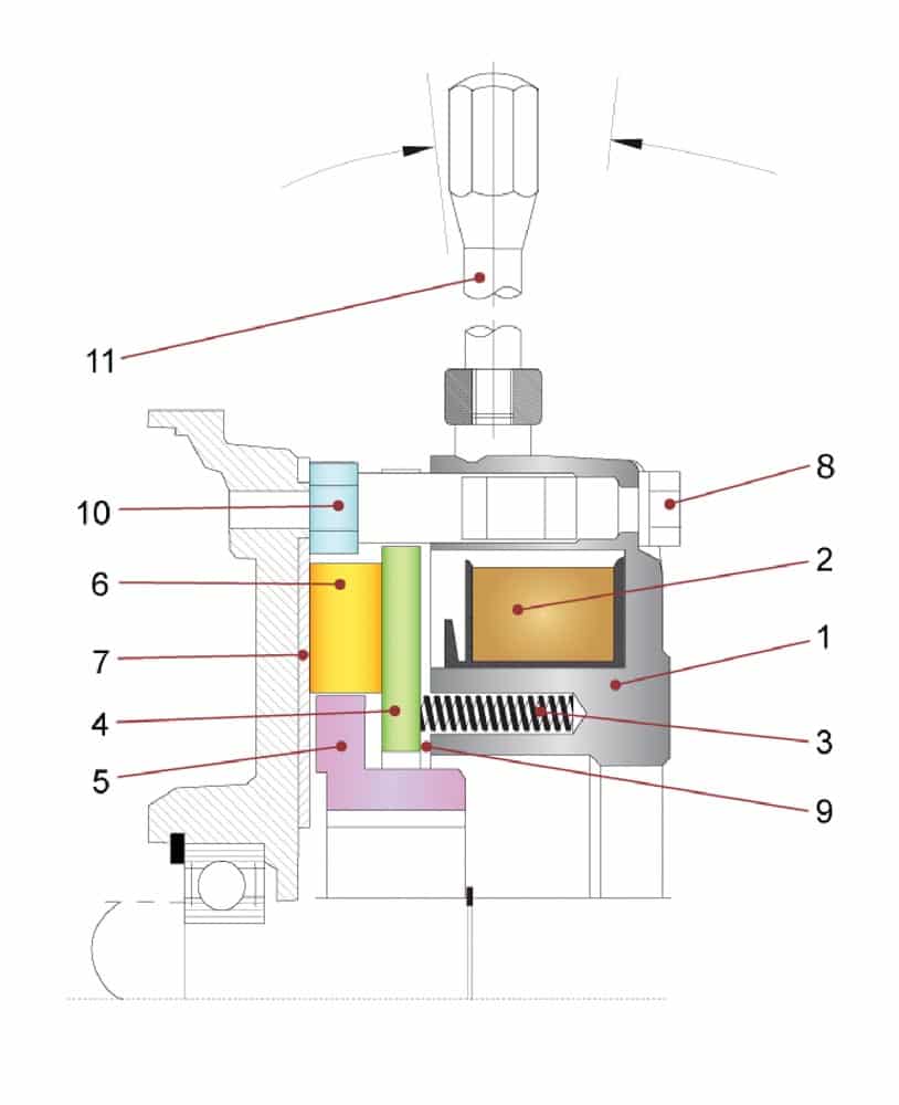
An electromagnetic spring-set DC brake consists of an electromagnet, comprised of a magnet housing and coil. The magnet is usually mounted to the motor endbell with adjustable mounting screws. Multiple compression springs are placed in machined pockets on the face of the magnet and are loaded to apply a spring force on a non-rotating armature. A friction lining is spline connected to a shaft hub and sandwiched between the armature and another suitable friction surface. With the hub axially located, a small air gap between the magnet and armature is adjusted using the hollow spacer mounting bolts.
Power Off (Brake Engagement)
In a steady state (power off) scenario, no DC voltage is applied to the magnet coil, so no current flows, and no magnetic field is induced. As the spring force is applied to the armature, the friction lining is sandwiched between the armature and friction surface, and a torque is developed, holding the shaft stationary.
Power On (Brake Disengagement)
When voltage is applied to the coil, current begins to flow, and a magnetic field is created. The magnetic field continues to build until it is large enough for the magnetic flux to jump the small air gap between the magnet and the armature, and complete a magnetic circuit. The magnetic force of the circuit compresses the springs, and the armature is pulled into the face of the magnet. The spring force is no longer applied to the friction lining, so the hub and motor shaft are able to rotate freely.
Brake Options
One advantage of a DC brake is its proven reliability. The KEB design incorporates redundant compression springs, which are rated for more than 10 million cycles each. The coil is completely encapsulated in epoxy and uses class H wire. High-energy friction linings, which are resistant to glazing and torque fading, are used. The armature is the only moving part in the brake, so there are no levers or linkages that can fail like their AC brake counterparts. Another advantage of the DC spring-set brake is its design flexibility and other available options. Some of the more common features required in elevator applications follow.
Manual Hand Release
A manual hand release allows an operator to open the brake without applying power to the magnet coil. This feature is primarily used for testing and troubleshooting but could be used in emergency situations, as well. A hand release is comprised of a yoke and handle, which are mounted to the back of the magnet housing. Mounting bolts run through the yoke and magnet housing and capture the armature. As the hand release lever is pulled back, the springs in the magnet are compressed, and the armature is pulled across the air gap, allowing the friction lining and shaft to rotate freely. For safety reasons, the lever requires a constant force or “constant effort” to keep the brake open – releasing the handle will cause the brake to engage.
Microswitch
The ability to monitor the state of the brake is an important feature for an elevator controller. Verification of the brake state improves the safety of the system and allows the control sequence timing to be optimized. Brake feedback also allows the controller to ensure that the brake isn’t being driven through at any point during normal operation. Engaging the brake while the car is still decelerating or driving the motor before the brake has completely disengaged will cause the friction disc to prematurely wear and shorten the brake operating life. A brake microswitch provides a feedback signal indicating the state of the brake – engaged or disengaged. Usually, the microswitch is configured to close when the brake has fully released. One way to implement a microswitch is by placing it in a machined pocket in the magnet housing. Additionally, a plunger is fixed to the armature, and its length is adjusted so that it is located just above the switch. As the armature pulls across the air gap, the plunger moves with it and pushes down on the switch, closing a contactor. It is important to use an industrial-grade switch that can handle the repetitive cycling of a lift application.
Noise-Dampened Designs
Audible noise is created in a DC brake when the armature actuates and makes contact with either the magnet housing or friction lining. The metal-on-metal noise during brake release is particularly pronounced with larger brake sizes. Larger brakes require larger armatures, which allow the passage of more magnetic flux. The increased mass of a larger armature has more kinetic energy, making for a louder contact sound.
KEB primarily uses two methods to reduce the noise in DC brakes. The first design requires placing a noise dampening material between the magnet and armature. The purpose of the material is to act as an insulator between the two metal materials and absorb the energy of the moving armature. However, care should be taken to ensure that the armature completely pulls into the magnet and that there is no residual torque created by the friction disc. While this method mitigates the metal-on-metal contact, it only reduces the noise created during brake release.
The second noise-dampening design in elevator brakes involves slowing the speed of the armature. Because the duration of the actual armature actuation is so short, this has no visible effects on the overall timing of the brake. The advantage of this solution is that the brake noise is improved in both the engagement and disengagement directions. KEB’s noise-dampened elevator solution using a special armature design is rated for less than 65 decibels at 1 meter as standard. If needed, further design considerations can be made to reduce the noise levels to below 55 decibels at 1 meter.
Overexcitation and Reduced Voltage Switching
It should also be noted that DC brakes inherently have switching delays, the time from when the brake is signaled to when the torque is developed or reduced. This is largely due to the fact that the engagement and disengagement of the brake requires the building and decaying of flux in the magnet, which is not instantaneous. The switching delays are even longer for larger brakes due to the increased inductance of the coil and the amount of magnetic field that needs to be built and decayed.
One solution to improve brake release delays is to overexcite the brake, or, apply a larger-than-rated voltage for a short duration until the armature pulls in. The air gap offers resistance to the magnetic circuit and a peak flux is needed in order to jump the air gap to create a circuit with the armature. After the armature pulls in, the amount of flux needed to keep it in place is considerably less. At this point, the brake voltage can be returned to its nominal value. This overexcitation switching helps develop magnetic flux but only improves the reaction times during brake release.
Brake engagement times can be improved by holding the brake released with a reduced voltage. As mentioned previously, once the armature is pulled across the air gap, it can be held in place with considerably less voltage. Holding at a lower voltage means there will be less flux in the circuit that needs to decay in order for the spring force to return the armature to its static position. Similar to the overexcitation switch, special brake switches exist which can hold the brake in at a lower voltage, thereby improving brake engagement times. Holding the brake open at a lower voltage also corresponds to less heating and lower coil losses over the life of operation.
Double-Brake Designs
Because the brake is critical to the safety of the elevator, some sort of braking redundancy in the system is required. The nature of the redundancy requirements can vary by the governing specifications and directives. One popular directive used worldwide is DIN EN 81 – Safety Rules for the Construction and Installation of Lifts. The part of EN 81 that pertains to electric lifts states that the electromechanical brake must have two independent sets of mechanical components able to brake a car. As it relates to armature-actuated brakes, there are several different ways redundant brake systems can be designed and applied.
Type DDN – Double Brake
One way to provide a redundant brake system is to utilize two independent brakes. This provides two separate electrical and mechanical systems. The brakes are often stacked together and shipped from the manufacturer ready to mount with flanges and preset air gaps. The brakes
should be dimensioned such that each individual brake is capable of stopping the elevator according to the governing code. Separate electrical circuits also imply that the brakes can be controlled by separate safety circuits from the controller, further improving system redundancy.
Type D8 – Split Armature Design
One method to reduce the overall size and cost of a double brake while still achieving the requirement of separate mechanical braking components is by implementing a split armature design. The brake utilizes one common magnet and two separate half armatures or “split armature.” Each armature has its own set of springs and is capable of decelerating the car by itself. The advantage of this solution is that the overall length of the brake is shorter than that of the stacked double brake. Also, the split armature design uses significantly less material and is therefore more economical than a true double brake. All options are available in the D8 design – both armatures can be adapted with separate hand releases and microswitch monitoring.
Emergency Brake in an ACO Situation
DIN EN 81-1 (Section 9.10) also requires a means of detecting and slowing an overspeed car in the up direction. In traditional geared applications, the electromechanical motor brake could not be considered an emergency braking device in an ascended car overspeed (ACO) situation, because it was not directly coupled to the traction sheave. Since MRL gearless machines incorporate the brake and sheave on a common shaft, the motor brake can now be considered an emergency brake if applied correctly. This is significant, because the motor brake could replace a Rope Gripper or sheave brake as the safety brake, thereby saving space and money. Both the KEB double brake (DDN) and split armature brake (D8) brakes have been TÜV certified to be used as safety brakes for ACO situations per EN 81-1. Customers should ask their motor and brake manufacturer to provide test results or certification from a third-party testing agency that the brake complies with the applicable emergency-brake specifications.
Conclusion
MRL lifts offer distinct space and efficiency advantages over traditional solutions, so their proliferation will continue. The motor brake is a very important component in the MRL machine design and can contribute to its compact design and serviceability. Armature-actuated spring-set brakes are a proven solution with few failure parts and a long operating lifetime. The design is flexible, and they can be easily configured to meet the requirements of the application. These brakes can even qualify as emergency braking devices, replacing bulkier, more expensive solutions. In short, spring-applied DC brakes meet the strict safety and functional requirements of the MRL application and are a viable brake solution.
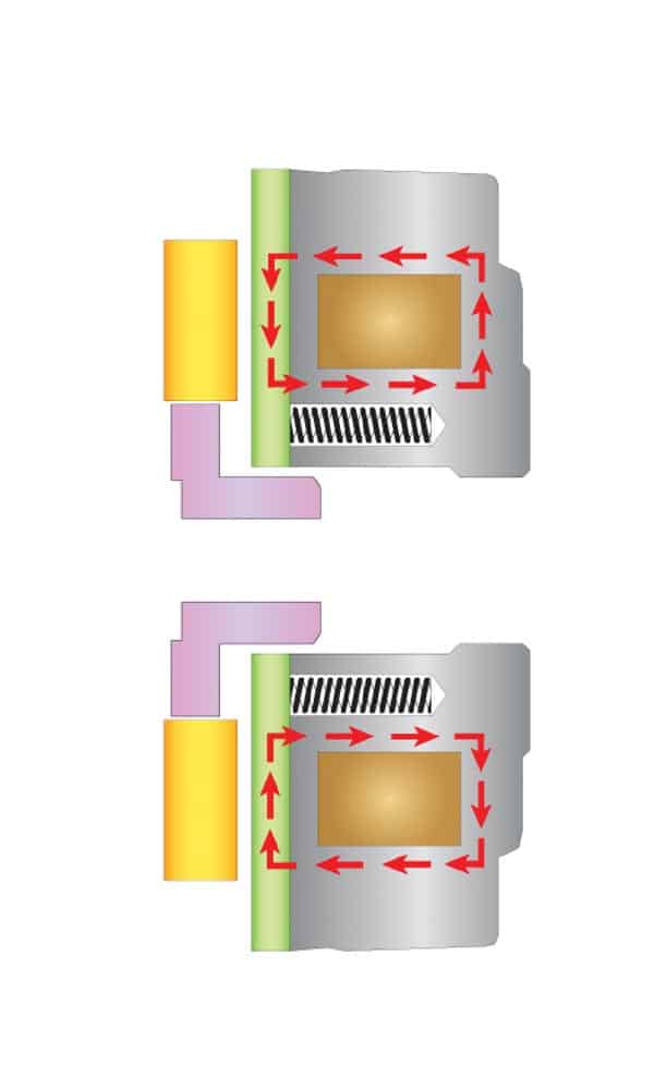
Power on (disengagement): Magnetic field pulls armature across air gap, freeing the shaft to rotate. 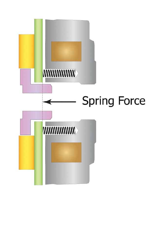
Power off (engagement): Mechanical spring force presses armature into friction disc. 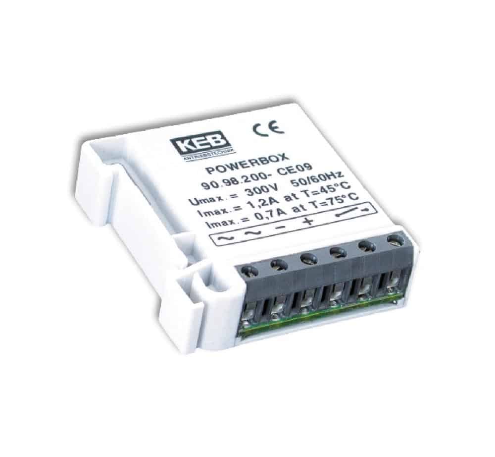
DIN-mount Powerbox overexcitation rectifier switch 
KEB DDN Double Brake with dual hand release 
KEB D8 Split Armature Elevator Brake
Learning-Reinforcement Questions
Use the below learning-reinforcement questions to study for the Continuing Education Assessment Exam available online at www.elevatorbooks.com or on page 121 of this issue.
- Why is a spring-applied brake sometimes referred to as a “fail-safe” brake?
- What happens when an operator holds a brake open with a hand release, then lets go of the hand release?
- Does a microswitch usually open or close when the brake is disengaged?
- What can be done to improve the switching times of DC brakes?
- Can a split armature design be used as a double brake?
Get more of Elevator World. Sign up for our free e-newsletter.


