The First Elevator Inspectors’ Manual
Feb 1, 2014
by Dr. Lee Gray, EW Correspondent
The authors of the first elevator code (see “The First Elevator Safety Code: A Mystery,” ELEVATOR WORLD, November 2006 and “The Code Writers of 1921,” EW, May 2008) faced a significant challenge in their attempt to articulate national standards. The scope of this challenge is reflected by the appearance (in fairly rapid succession) of the first four editions of the American Standard Safety Code for Elevators, Dumbwaiters, and Escalators (1921, 1925, 1931 and 1937). The fourth edition was accompanied by a new publication, the American Recommended Practice for the Inspection of Elevators: Inspectors’ Manual (ASA A17.2-1937). The authors of the new manual included individuals who had been involved in writing the first elevator codes, and the members of the Inspectors’ Manual subcommittee were identified as follows:
- Kyran A. Colahan – chairman (district manager, Engineering Department, American Mutual Liability Insurance Co.)
- John A. Dickerson – secretary (mechanical engineer, National Bureau of Standards)
- Clarence R. Callaway (president, Gurney Elevator Co.)
- Patrick F. Foley (formerly chief elevator inspector, New York City Department of Buildings)
- Bassett Jones (consulting engineer and partner, Meyer, Strong, and Jones, Inc.)
- Walter S. Paine (manager, Engineering and Inspection Department, Aetna Life Insurance Co.)
- George H. Reppert (engineer, Otis)
- James G. Shaw (Flushing, New York)
- Walter F. Stutz (chief, Engineering Instruments and Mechanical Appliance Section, National Bureau of Standards)
- James L. Keane (Aetna Life Insurance; alternate for Paine)
- Henry F. Richardson (Meyer, Strong, and Jones; alternate for Bassett Jones)
The sponsor organizations for this initiative included the National Bureau of Standards, the American Institute of Architects and the American Society of Mechanical Engineers. The American Standards Association approved the new manual in July 1937.
The efforts of the authors and their supporting agencies produced a work that provides unique insights into the world of vertical transportation in the 1930s. This glimpse into the past is made more interesting, because, although the manual lacked the authority of a “code” (note the key word “recommended” in its title), it was perceived as serving a critical function in supporting the new elevator code’s implementation. The authors’ careful negotiation of these facts is reflected in the manual’s preface, which also carefully noted the legal status of the code itself:
“This manual is intended to serve as a guide for the general use of elevator inspectors. It is based on the requirements of the American Standard Safety Code for Elevators, Dumbwaiters, and Escalators, and reference to the rules of that code is frequently made in the text, but it must be clearly understood that, while representing good practice, both the manual and the code have no legal force. While many legal codes are based upon the American Standard Code, inspectors should be guided by whatever elevator code is legally in force, and the recommendations made herein applied only so far as they harmonize with legal requirements.”
The reference to “good practice” (which today would likely be called “best practice”) was intended to be followed when inspecting elevators. This resulted in the manual having a high level of specificity with regard to situations typically encountered during inspections.
The manual begins with an introduction that includes a section on personal safety. In addition to the admonition that inspectors should always be aware of their surroundings and carefully track “moving objects,” information was also provided on what to wear: “The inspector should be suitably clothed before starting the inspection. A one-piece suit of overalls is probably the most desirable. Keep buttons, particularly cuff buttons, buttoned.”
Following the introduction, the manual is divided into two primary sections or parts: “Part I Routine Inspection,” which concerns existing installations, and “Part II Initial or Data Inspection,” which concerns new installations. The suggested equipment needed for routine inspections was an electric flashlight, a 6-ft.-long rule, a thickness gauge, a small test hammer (preferably a 1/2-lb. ball-peen or machinist’s hammer), a piece of white chalk and a small mirror (preferably made of metal). In many instances, the manual suggested how this equipment should be utilized. The hammer was to be used during the inspection of overhead sheaves, which:
“. . . should be thoroughly examined and tested with light blows from a hammer. . . . [Sheave] arms or rims indicate a defect by the sound given out (this sound is dull and flat and quite unlike the ring given by sound metal).”
This auditory inspection was accompanied by a visual inspection with all sheave parts “carefully examined for cracks.” If the hammer test indicated a potential problem but no cracks were visible, it was suggested that “very minute or hair cracks” could be discovered by “covering the suspected section with machine oil, allowing it to stand a few minutes, wiping off all the surplus oil with a rag or waste, and then coating with chalk.” The chalk coating would reveal any cracks, which were made visible by the oil that had penetrated into the sheave’s surface. Chalk was also used when inspecting cables to mark the sections that had been examined. The mirror was to be used “in examining ropes or other parts of equipment normally inaccessible.”
The manual clearly reveals the importance of elevator operators during this period, as well as the fact that a wide range of old and new technologies would be encountered. Several sections of the manual included the specific instructions to be given to operators to facilitate inspections of the hoistway, car equipment, ropes, pit, etc. Many freight elevators in the 1930s were still controlled by “hand operating cables” or shipper ropes, the original system of elevator control introduced in the 1850s. These were typically tiller ropes, which were composed of six strands of 42 wires each, with each strand and the combined wire rope wrapped around hemp cores. The result was an extremely flexible rope that was well suited to this application.
In addition to the shipper rope, some belt-driven freight elevators also employed a centering rope that, as its name implies, was located between the two shipper ropes. If pulled, it immediately shifted the driving belt to the idler sheave and applied the brake, thus stopping the car. (This feature was included in Elisha Graves Otis’ 1861 patent, which is primarily known for its ratchet safety device.) In car-operating systems that featured lever control switches, it was important “to determine whether the handle returns to the neutral position and whether it locks in this position.” With newer “automatic” systems, it was important to “determine whether floor buttons stick, and whether stop and alarm buttons work properly.”
The inspection of electric elevators included the controller and its associated wiring and fuses. Inspectors were advised to “examine the back of the control board to determine whether there are any loose wires and any loose, broken or cracked resistance grids or tubes.” Inspectors were also instructed to examine the “starting-resistance grids to make sure that there is no lint, dust, paper or other combustible material on them,” because this was a “common source of fire in elevator machine rooms.” In addition to these concerns, inspectors were alerted to common practices that, perhaps, resulted from the fact that electric elevators had been in operation for approximately 40 years and building maintenance men had developed potentially dangerous shortcuts to keep their elevators running. Inspectors were advised to:
“. . . examine fuses on the controller panel to determine whether any of the fuses [had] been replaced with larger sizes or with heavy wire, nails or similar objects, and whether any fuses [had] been rendered useless by soldering wire or metal strips from ferrule to ferrule.”
The inspection procedures outlined thus far are found in Part I, which included the following sections: “Inspection Made from Inside of Car,” “Inspection Made Outside of Hoistway,” “Inspection Made from Top of Car,” “Inspection Made Overhead,” “Machine Inspection – Electric,” “Machine Inspection – Belt Drive,” “Machine Inspection – Hydraulic,” “Handrope Mechanism,” “Slack-Cable Inspection,” “Slack-Cable Devices” and “Inspection Made in Pit.” Each section was further subdivided as needed. For example, “Inspection Made from Top of Car” included “Counterweight Fastening and Counterweight Buffer,” “Cable Fastening,” “Cable Inspection,” “Cable Tension,” “Cable Lubrication,” “Normal Slowdown and Stop Switches,” “Upper Final-Limit Switch,” “Car Clearance,” “Rail Surfaces,” “Joints and Fastenings,” “Alignment of Rails,” “Door-Operating Device,” “Governor-Rope-Shackle-Releasing Carrier” and “Special Slowdown of Car-Latching Devices.” This information and its associated inspection procedures also informed activities outlined in Part II.
The manual recommended a team of two inspectors be assigned to conduct the initial inspection of new installations. In addition to the equipment previously specified, the team was also to be equipped with a “calibrated stopwatch” capable of “measuring time to one-fifth or smaller fraction of [a] second,” a 50-ft.-long steel or cloth tape, a handheld tachometer (preferably one provided with a 12-in. circumference wheel) and a “small spirit level.” The manual’s authors assumed the “suitable test weights” required for “making the load tests” would be “furnished by the elevator manufacturer.” The stopwatch and tachometer served the same purpose – measuring the speed of the elevator to ensure it met the project specifications when carrying its “full contract load.”
The 50-ft. tape was used to “measure the distance between two of the intermediate floor landings as far apart as possible, unless this distance can be readily determined from the layout blueprint.” The inspectors would then record the time of the car travel in the up and down directions “at full contract load” using the stopwatch. The recommended formula to determine the car speed was S = 60h/t, where “S is the speed in fpm, h is the travel of the car in feet for which the time has been taken, and t is the time in seconds.” It is interesting to note that a set distance or number of floors was not specified and that no clear directions were provided on how the inspector was to know when to start or stop the watch. The handheld tachometer offered the inspectors a more precise way of measuring the car’s operating speed. The measurement was to be taken “in the machine room, it being understood that the tachometer reading should be taken after the car has reached its constant speed.” However, holding the 12-in. wheel of the tachometer steady against a moving hoist rope atop a sheave in the machine room must have presented an interesting challenge to the inspector, both in terms of safety and the skill needed to obtain an accurate reading.
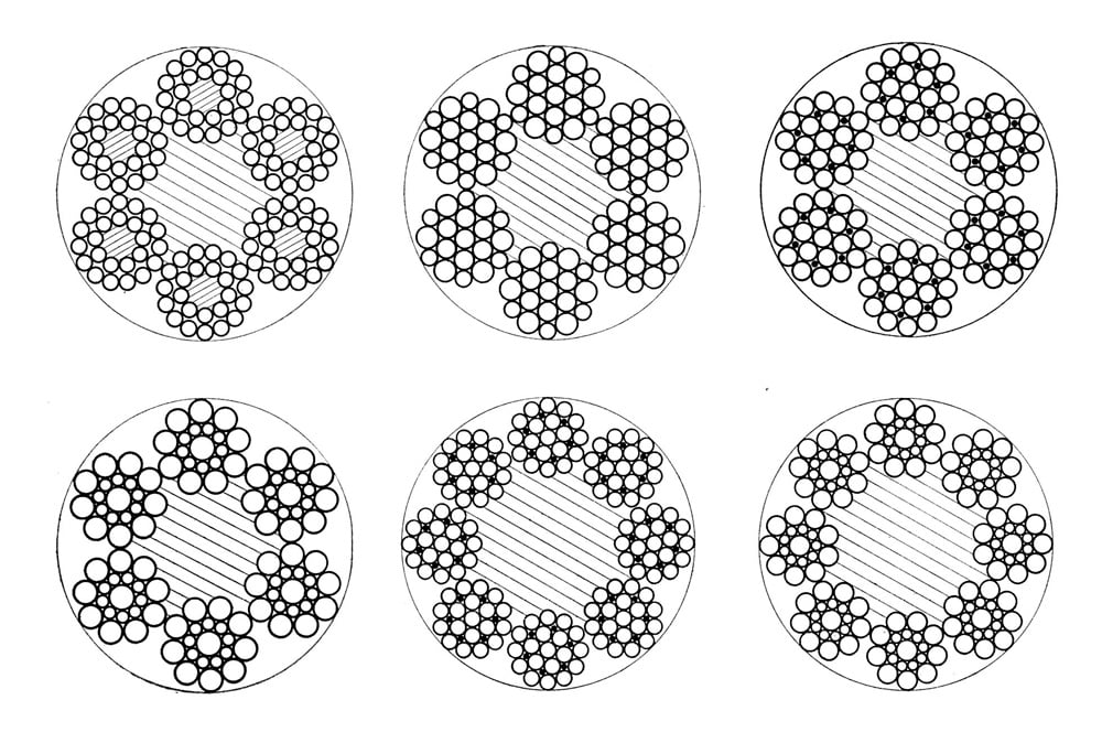
Part II also covered a broad range of initial inspections: “Brake Action,” “Normal Slowdown and Stop Switches,” “Final-Limit Switch and Oil-Buffer Tests,” “Special Terminal Stopping Devices,” “Car Safety Test,” “Governor Tripping Speed,” “Platform Level,” “Sliding Distance and Rail Condition,” “Counterweight-Safety Test,” “Machine-Room and Overhead-Sheave Equipment,” “Control and Operating Equipment,” “Check of Car Capacity and Dimensions,” “Emergency Exits and Car Enclosure,” “Car Door or Gate,” “Emergency Release,” “Floating Platform,” “Lighting Fixtures and Car Lighting,” “Glass in Car,” “Car Location (Numbering),” “Hoistway Dimensions and Clearances,” “Pit Clearance,” “Car and Counterweight Overhead Clearances,” “Hoistway Enclosure,” “Hoistway Doors,” “Hoistway-Door Interlocks,” “Hoistway-Door Electric Contacts,” “Ropes” and “Rope Sockets.” Given the detailed nature of these topics and those addressed in Part I, it is somewhat surprising to find that the manual’s appendix is limited to a sample “Data Inspection Form,” four tables (addressing the factors of safety for cables, clearances, safety stopping distances and the carrying capacity for power passenger elevators corresponding to effective platform areas), two pictures (depicting correct and incorrect cable socketing) and six line drawings (depicting wire rope types).
This brief examination of the 1937 Inspectors’ Manual serves as a reminder of the complexity of this era, which included rapid changes in elevator technology and the introduction of new machines, activity counterbalanced by the sustained presence of older machines that still served critical functions in many buildings. It is important to note that the Inspectors’ Manual was designed to accompany the 1937 American Standard Safety Code for Elevators, Dumbwaiters, and Escalators. Also, the new Inspectors’ Manual contained no references to the inspection of escalators.

Cover, American Recommended Practice for the Inspection of Elevators: Inspectors’ Manual 
“Table 4: Carrying capacity for power passenger elevators corresponding to effective platform areas” from the American Recommended Practice for the Inspection of Elevators: Inspectors’ Manual 
(l-r) Correct lay maintained after socketing and incorrectly socketed wire rope showing loss of rope lay from the American Recommended Practice for the Inspection of Elevators: Inspectors’ Manual
Get more of Elevator World. Sign up for our free e-newsletter.


