The Use of Cameras to Evacuate People in Elevators
Oct 1, 2011
by John Trett and Charles Simpkins
This paper was presented at  Lucerne 2010, the International Congress on Vertical Transportation Technologies and first published in IAEE book Elevator Technology 18, edited by A. Lustig. It is a reprint with permission from the International Association of Elevator Engineers
  (website: www.elevcon.com). This paper is an exact reprint and has not been edited by ELEVATOR WORLD.
Key Words: Cameras, monitoring, evacuation, communication, security, emergency
Abstract
Using cameras extends the use of elevators to evacuating people at a much quicker rate during fire or other emergency situations. The cameras are used to see if the car, hoist way and motor room are clear of debris, damage and smoke. Additionally the system can be used for security applications. This paper dis-cusses the technology needed to allow cameras to be reliably used and monitored, locally or through the internet from a remote location. The communication links are dis-cussed showing the immense possibilities of the system to security managers, building owners and the emergency services.
1. Introduction
Traditionally passenger elevators are not used to evacuate people from a building in the event of an emergency. The emergency services have the use of special fire fighting elevators that are provided to harmonised standard EN81-72 in Europe, with additional safety rules for construction and installation, and the normal passenger elevators are left unused.
Consequently in an emergency people have to use the emergency staircases and those with disabilities have to make their way to refuge areas and await the arrival of the emergency services.
It would maximise the speed of evacuation and make the building safer if all elevators could be used to evacuate passengers safely even be-fore the emergency services arrive. This is true not only for high rise buildings but also for low rise buildings, and for elevators installed in existing buildings. A way is needed to establish the elevators are still safe to use with no risk to the passengers.
Even with the additional safety features of the fire fighting elevators, the emergency services do not have information about the environment where they exit the elevators as they are not aware of any risks, or hazardous situations, or events on each landing (e.g. fire or smoke).
The emergency services are de-pendent on the foresight of designers in providing them with the necessary facilities to operate effectively within the building, and to assist the people to escape in both high and low rise buildings.
To use the elevators for as long as possible, without any danger to the passengers, requires systems that the security managers, building owners and emergency services can use to monitor the safety of the elevators and make them available to the passengers until the fire fighting or emergency crews arrive.
The use of cameras allows the security managers, building owners and emergency services to evaluate the safety of the building and elevators to access the risk of using the elevators to evacuate the building. They can check for smoke, fire, damage in the shaft and guides etc., before moving the cars in an emergency.
They can evaluate significant hazards such as:
- Fire, heat or hot gases which may have spread into an elevator well or machinery
- Fire, heat or gases near to the building power supplies.
- Exposed or obstructed elevator equipment Continued
- Elevator unsafe for passengers and fire fighters
- Elevator will become unsafe while being used by passengers and fire-fighters
- Use of elevators by regular passengers if there is a significant delay in the arrival of the emergency services.
- Flow of water into the elevator shaft and well
- Entrapment of people on fire protected lobbies and refuge areas
- Unsafe environment for fire fighters and people waiting to be rescued.
- Visible failure of structural integrity
- Incorrect location of elevators for use by fire fighters
- Trapping hazards
- Failure or malfunction of the elevator
- Human error and behaviour
The cameras must be placed in the cars, hoistway, machine room and landings so that all areas around the elevators can be seen. They must be linked to a central command post, or security or technical centres. The cam-eras and cabling and internet and other access must be robust and protected for emergency conditions. The centre must be able to have access to all cameras and the cameras must have pan, tilt and zoom capability. They must be able to allow access to elevators in an emergency situation once they have assessed the hazards. They can addition-ally use the cameras in security applications.
In response to this, C.E. Electronics have developed a number of products and interfaces, which can be installed and used easily by security centres to give the information required. The products and software are so flexible that the system can be customized to meet the demands of the building, security officers, consultants, architects and emergency services. The products have been successfully tested for the market and are the forefront of technology.
The basic elements are:
- Robust, weatherproof cameras with pan, tilt and zoom capability that can be mounted in the car, machine room, hoist way and landings.
- Various solutions linking these cameras to a central security centre, including secure internet and wire-less technology.
- The ability of the security room operator to select different cameras and zoom onto a location of interest.
- Custom software to allow the security centre to decide where and how the products are used.
- Modular design.
- Ability to provide the passengers with information from the security room, for example using C.E. Electronics TFT screens with video in the car.
The system is able to send pictures to the security centre such as:
- Views of all landings, the hoist way, the car and the machine room.
- Identification of passengers with disabilities.
- Position and direction of travel of individual cars
The system enables the security centre to evaluate the hazards in the building and allow access to safe areas, and to allow the use of all elevators in an emergency. It also allows the images to be used in security situations such as unwanted visitors and terrorism, and monitor se-curity access systems.
This paper discusses the specification, structure and application of this product.
2. Interfaces To Product
C.E. Electronics has developed a number of camera applications and interfaces to securely and robustly send and receive signals to and from the security centre. These include Ethernet, wireless and fixed wiring solutions.
C.E. Electronics has developed software to process sig-nals so that the security centre can select and control the cameras.
2.1. Interface
A unit is mounted in the security room to receive signals from the cameras and send signals to control the cameras.
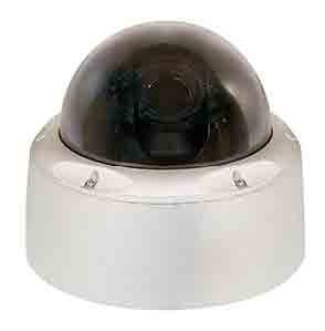
C.E. Electronics are using an intelligent IP network camera system utilizing PTZ IP (Pan Tilt and Zoom Inter-net Protocol) cameras that are mounted in a waterproof domed housing.
Because of the weight and wiring constraints that face us, C.E. Electronics can use a wireless solution. Our cam-eras have the option of using antenna cards to transmit the video at 30fps@vga at distances up to 1.2 miles. If fibre optic cable is available then that could be utilized as well.
This Security/Escape Camera system can be tied into an existing Intelligent IP network or can be built on its own IP network.
Our recommended approach to this would be as follows; C.E. Electronics supplies typical PTZ IP cameras with .8 low lux, 360 degree rotation and 90 degree tilt, 10X auto focus zoom in a weatherproof housing, broadcasting the video via wireless transmission or fibre optic cable to the machine room. In the machine room we can provide the Ethernet connection for all the cars to one box.
“Others” provide the Ethernet lines to the security control centres.
C.E. Electronics provides video servers based on a Windows server operating system to interface the cameras over a Cisco or other intelligent network.
C.E. Electronics provide software utilizing “CE’s Shot Viewer” software in conjunction with C.E. Electronics third party software interfaces. This software combines the functions of the video multiplexers, digital video recording and the system administration control console. This would include configure-on-the-fly monitoring for one or all ten simultaneous feeds with “hot spot” capability. Recorded images can be automatically stored in user-customized data file folders. Control of the cameras is with keypad and joystick.
3. CAMERA capabilities.
3.1 Car Cameras and Video
C.E. Electronics supply a complete package including car cameras to reduce costs and make interfacing easier.
They are CCD colour analogue cameras with 350 lines of resolution and a 3.6mm lens providing an 80 degree field of view with a 1.0 low lux rating. Mounted they are 57mm x 36mm x 31mm and can be powered directly off the C.E. Electronics ElitePiTM system.
In each car can be mounted a C.E. Electronics Main and/or Auxiliary ElitePiTM TFT screen with video or TV showing from a video source. An additional camera com-posite video signal from the security operator “source” is routed through a C.E. Electronics 2×8 A/B Video switch with auto gain features designed specifically for the ele-vator environment. This allows video sources to be switched. When emergencies arise, signals can be sent via the programming serial data link from the security room through the security Ethernet link (fibre optic link, twisted pairs and/or coax or wireless link). Cameras lo-cated in the security room or other source can be switch multiplexed to the individual car screen, and the passen-gers and security operators can see and communicate with each other.
3.2. Car Position Identification – Video Overlay
C.E. Electronics can supply, using our MicroCommTM system, a video overlay on the camera display in the se-curity room, which shows the position and direction of the car. The security operator will know where the car is and the direction of travel to assist him in assessing the situation and providing information to others.
4. Network system
The network system provided by C.E. Electronics is a fully integrated package. Signals from cameras can be sent in either direction over the internet, and switched and controlled to the best advantage of the security officers The output from the cameras in the machine room can be provided in either of two formats.
- Returned to a standard NTSC or PAL composite video output per car in the machine room.
- Wired directly into C.E. Electronics analogue to IP module similar to a Video IP Network Station. This station could then be placed on the Intelligent Ethernet network.
If the car cameras are wired into the IP network station they can be added to an existing IP security system or placed on the same system that would support the IP based Security/Escape Cameras.
The IP Network system proposed offers a very man-ageable, scalable solution with excellent reliability for an affordable price. The Scalability of this system can pro-vide as much or as little as needed. System integration and operation is extremely familiar utilizing industry standard components.
5. Reliability
The systems have successfully passed test for vibration and deterioration with age. They are very robust and well protected for vandal resistant sites. The protocols de-signed by C.E. Electronics are very robust and pass EMC standards for noise immunity.
6. Adding Other Units to The System
The C.E. Electronics MicroComm ™ 3-shaft-wire sys-tem has all the information necessary to allow products in the C.E. range to be connected, including 16 Segment and Dot Matrix Indicators, Arrival Gongs, Speech Units, Hall Lanterns and Scrolling Message Units. All units are connected serially (daisy chained) so minimum additional wiring is required. This makes it an ideal system for modernization. Other links and protocols include CAN, Echelon, Ethernet and RS232/RS485.
7. Conclusions
In this paper we have explained the specification and structure of the C.E. Electronics video display systems, and how they can be used to give superior information to the security managers, building owners and emergency services to assess the risk and safety of the elevators being used to evacuate the building. They can check for smoke, fire, damage in the shaft and guides etc., before moving the cars in an emergency. They can also be used for security monitoring of a building, giving them a superior system to optimize elevator operation.

Figure 2. Wireless solution to transmitting video signals 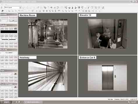
Figure 3. Monitoring screen showing typical view of layout of information on the screen in the security centre monitoring a building 
Figure 4. Security Officer ‘talking’ to passengers in a car 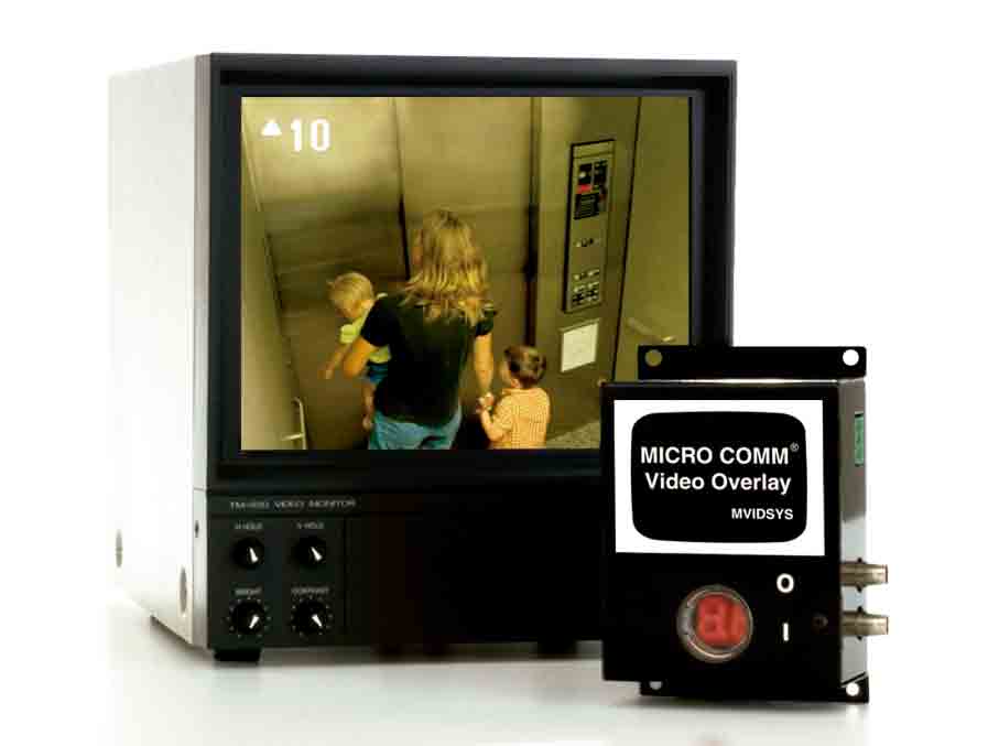
Figure 5. Video overlay of car position and direction 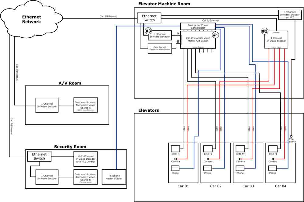
Figure 6. C.E. Electronics networking system 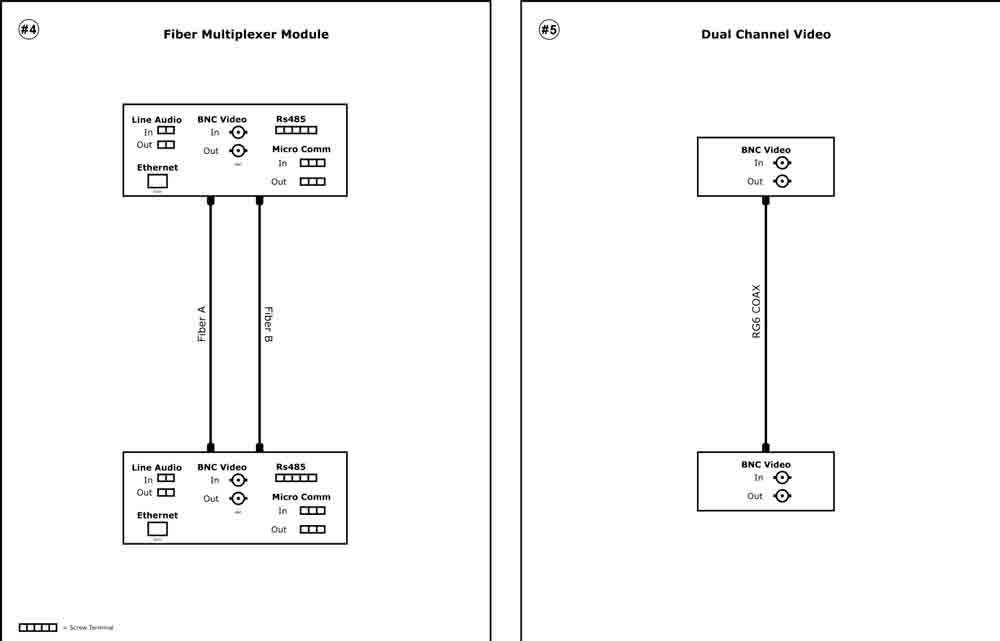
Figure 7. C.E. Electronics Fibre Multiplex and Dual Channel Video Modules 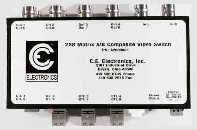
Figure 8. Typical C.E. Network Block 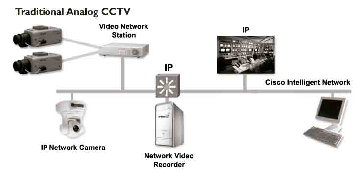
Figure 9. Traditional Analogue CCTV system
REFERENCES
(European Standard)
EN81-72 Safety rules for the construction and installation of lifts – Particular applications for passenger and goods passenger lifts – Part 72: Firefighters lifts
(Concept)
The original ‘lifeboat’ concept came about from talks with James Fortune who had to evacuate a high rise building via the stairs. C.E. Electronics put together a system that works.
Get more of Elevator World. Sign up for our free e-newsletter.


