Traction for Field Personnel, Part One
Aug 1, 2017
Unintended loss of traction, resulting from component deterioration, for example, is very hazardous and can allow an elevator to move uncontrolled. Four factors determine and control traction:
- The traction ratio of car and counterweight
- The area of contact of hoist ropes on the drive sheave
- The coefficient of friction/friction factor between the hoist ropes and drive sheave
- Acceleration/deceleration
This article provides information on traction requirements to prevent loss of traction from occurring due to unnoticed wear and inadequate maintenance, inspection and testing. How do the suspension members not slip on a traction sheave? What traction force prevents the ropes from slipping on the sheave from the empty car load to a fully loaded car? Maintaining traction falls under elevator maintenance.
Learning Objectives
This Continuing Education article will provide education needed for elevator personnel who work on electric elevators to understand the importance of component condition, code requirements, measurement and testing of traction to ensure the highest level of safety. In this article, the reader will learn:
♦ Maintenance on suspension members is required by code.
♦ Maintenance must include measurement of rope and sheaves at adequate frequencies to ensure compliance.
♦ The types of friction and how they apply to elevators
♦ Which sheave grooves are used in the elevator industry
♦ How a capstan winch can help with visualizing traction force
This course is divided into two parts: Part One will be the principles of traction at a level a mechanic should understand; Part Two will be the components used in elevator systems that provide safe traction. The principles of traction will be applied, and indicators of traction problems, how to test traction and the code requirements to assure traction degradation does not occur will be explained.
All major components in elevators, escalators, moving walks and dumbwaiters have design requirements in the code. The code in the U.S. and Canada is ASME A17.1/CSA B44. Field technicians and mechanics have no design experience and are not responsible for design, but knowing the design basics can help one understand what is happening.
Design Requirements
A17.1/B44 code requirements call for traction to be provided, maintained, tested, and repaired if components show signs of noncompliance. To understand traction applications in an elevator system, it is helpful to relate it first to something we experience, and identify the principles in play.
In the simplest case, when you park your vehicle on a hill and set the emergency brake, there must be some force preventing it from sliding down the hill. The emergency brake is not the force providing the road/rubber frictional interface, though friction prevents rotation of the wheels with a brake pad/brake surface interface. The friction of the rubber tire mounted to the wheels is also preventing the tire from spinning on the wheel, but the rubber/road interface is where traction is required to prevent the vehicle from slipping down the hill on the road surface.
Force inherent in the rubber tire and the road surface holds the vehicle from slipping down the hill. If you drop an ink pen on the same steep hill you park your vehicle, there is inadequate traction to stop and hold the pen, yet the vehicle stays parked like a rock. Why does one stop and not the other? Friction.
Friction is a component of the science of tribology. Friction is the force resisting the relative motion between two solid surfaces, fluid layers and material elements sliding against each other. There are several types of friction:
- Dry friction resists relative lateral motion of two solid surfaces in contact. Dry friction is subdivided into static friction (“stiction”) between nonmoving surfaces and kinetic friction between moving surfaces.
- Fluid friction describes the friction between layers of a viscous fluid moving relative to each other.
- Lubricated friction describes fluid friction where a lubricant fluid separates two solid surfaces.
- Skin friction is a component of drag, the force resisting the motion of a fluid across the surface of a body.
- Internal friction is the force resisting motion between molecular elements making up a solid material while it undergoes deformation.
Elevators utilize the principles of dry friction when considering the frictional relationship between the suspension members (ropes or belts) against a traction sheave turned by an electric motor. Unbalanced masses suspended on each end of the suspension members (the car and counterweight) create a variable normal force (the support force exerted upon an object in contact with another stable object) measured in Nm2 (Newtons per square meter), kPa (kilopascals) or psi (lb./in.2) over the traction sheave. 1 psi = 6,895 Pa or 6.9 kPa.
Like where the rubber meets the road in the example of a parked vehicle, this article will be about where the suspension members contact the sheave and the resultant force that prevents the heavier counterweight from dragging the empty car up into the overhead or fully loaded car from dragging the lighter counterweight into the overhead (slipping traction).
Friction is a dimensionless value created by physical properties when two surfaces touch and forces are applied to the two surfaces in different directions. It is a variable force that changes based on the materials, loads, lubrication, etc. Because there are multiple items, together, they have variable properties and a coefficient of
friction.[1]
Dry friction arises from a combination of materials, inter-surface adhesion, surface roughness, surface deformation and surface contamination. The complexities of these interactions make the calculation of friction impractical and necessitated the use of empirical (real-world) testing for analysis and the development of theory. Leonardo da Vinci wrote the earliest recorded rules of sliding friction after such empirical testing. Further testing was documented by Guillaume Amontons and resulted in Amontons’ First Law: the force of friction is directly proportional to the applied load.
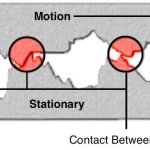
No matter how smooth the surface feels or appears, there will always be some quantity of jaggedness — high and low spots at a molecular level — called asperities. As shown in Figure 1, both the surfaces have high and low areas. A classic example at a macroscopic scale is sandpaper: the higher the grit value, the smaller and closer the asperities. For sandpaper, the characteristics of asperities are a function of the materials used to fashion it.
The presence of contaminants and lubricants affects how the friction relationship of the surfaces will behave. Think of a rubber tire on the road again: on a dry road surface, there is higher friction, but if oil is present, there is lower friction, because the voids in the asperities fill up, and the oils can create rolling balls of liquid, eliminating the locked nature of the asperities.
Continuing with Figure 1, if only the high points of the two materials are touching, what may look like the entire surface touching is, in fact, not substantially touching. When the materials are pressed closer together with a force, there is more locking interaction of the materials because of the high points of material deformation or breaking off, creating more interlocking of asperities. Bolted connections utilize this property; the higher the bolt torque, the higher the dry friction preventing slipping of the bolted connection.
As asperities are invisible to the naked eye, scientists continued to test different materials and their qualities, and his further experimentation led Amonton to his Second Law of Friction: the force of friction is independent of the apparent area of contact. We know today that the coefficient of friction and the available friction sometimes change. However, centuries ago, empirical testing showed friction could vary with varying areas of contact, depending on the materials tested and variable forces being applied.
Two types of dry friction are static and sliding (kinetic). This also confounded early scientists in understanding the friction relationship. Given the same materials and applied forces, static friction was always higher than sliding friction. For example, if a car is at rest, then accelerating, the car will move when the drivetrain turns the tires, but, if you gun the motor and spin the tires, the car does not move forward as quickly. The first is static friction, and the second is sliding friction. This was defined by Charles-Augustin de Coulomb, who developed Coulomb’s Law of Friction: kinetic friction is independent of the sliding velocity.
Within an area of contact, dry friction is also known as “Coulomb friction.” Coulomb developed the following formula to calculate the friction force commonly used today.[3]
Ff ≤ µFn (Equation 1)
where Ff = the force of friction parallel to the surfaces in a direction opposite to the net applied force, µ = the coefficient of friction, a property of the contacting materials, and Fn = the normal force exerted by each surface on the other perpendicular to the surface.
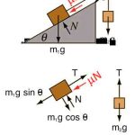
Developing a value for the coefficient of friction is simply illustrated with the inclined plane and its free-body drawing underneath (Figure 2). The surface of the inclined plane is one material, and the sliding box is another. It is counterweighted in this experiment to control the forces of movement.
The coefficient of friction is an empirical (observed or measured) value. Today, textbooks of materials and mechanical properties provide tables of coefficients of friction for common materials. For our purpose in this course, we will use a typical traction steel to a cast-iron sheave; that value is generally 0.08-0.1, with a value used in design of 0.09.[4-6]
A coefficient of friction of zero would indicate no friction. Teflon to Teflon can have a coefficient of friction as low as 0.004. Most combinations of dry materials have coefficient of friction values between 0.3 and 0.6. Silicone rubber or acrylic rubber-coated surfaces have a coefficient of friction that can be substantially larger than 1. Rubber, in contact with other surfaces, can have coefficients of friction from 1 to 2. When the value is greater than 1, it implies that the force required to move (push or pull) an object along the surface is greater than the normal force applied to the sliding surface on the object. The higher the value, the higher the friction.
If a 10-kg (22-lb.) block of material is pulled on a surface, and the coefficient of friction (µ) is 1, it takes a force of at least 98 N (22 lbf) to move the object. From Equation 1, we get:
Ff ≤ 1 * 98N (Equation 2)
Ff ≤ 98N
If a 10-kg (22-lb.) block of material is pulled on a surface, and the coefficient of friction (µ) is 0.5, it takes a force of at least 49 N (11 lbf) to move the object. Thus:
Ff ≤ .5 * 98N
Ff ≤ 49N
If a 10-kg (22-lb.) block of material is pulled on a surface, and the coefficient of friction (µ) is .09, it takes a force of at least 8.8 N (2 lbf) to move the object. Using Equation 2:
Ff ≤ .09 * 98N
Ff ≤ 8.8N
What this indicates is the steel-to-cast-iron coefficient of friction in elevator traction appears close to the slippery end of the range, around 0.09. Something else must be going on. One factor is the masses involved: for example, if an elevator system has 50 kN (11, 240 lbf) of mass, the friction force required to move the object is raised, as well. Using Equation 2:
Ff ≤ .09 * 50,000N
Ff ≤ 4,500N
Other factors are the angle of wrap or arc of contact around the sheave and type of groove profile.
The available traction of a sheave with a round steel-wire rope is found by the following equation:
α = efaθ (Equation 3)
where α = available traction of drive-sheave grooves at impending rope slip; e = base of natural logarithms (2.71828); fa = the apparent coefficient of friction, which embodies the actual coefficient of friction and the shape of the groove; and θ = arc of contact subtended by suspension ropes and drive sheave (rad).
In plain terms, e is a fixed constant; the exponents are fa, a value; and θ is the angle of wrap, a straight overwrap of 180° (3.141 rad) of wrap, for example. If there is a smaller exponent, there is less available traction; if there is a higher exponent, there is higher available traction. This is the basic equation for a U-groove sheave. Traction demands in higher speed elevators require more traction. If all the variables are fixed, how could we increase a?
In the 1920s, Frederick Hymans (ELEVATOR WORLD, February and March 2017)[3] and A.V. Heilborn studied the traction interface in steel grooves and steel-wire ropes and wrote the seminal book all traction elevator companies today use to teach engineers how to determine the tractive force that will not cause slipping in elevator designs. Der neuzeitliche Aufzug mit Treibscheibenantrieb (The Modern Elevator with Traction Drive) was published in 1927.[7] Without such research, it is likely high-rise buildings would not have been possible, and the world would be limited to low-rise, low-speed systems.
In terms of available traction, the µ doesn’t change, but the friction factor can change due to rope pressure increases when the groove material is removed in the sheave groove, such as in an undercut U-groove. This brings us to the final equation for traction:
T2/T1 = efaθ (Equation 4)
where T1 = the larger hoist-rope tension (N or lbf), T2 = the smaller hoist-rope tension (N or lbf), e = base of natural logarithms (2.71828), fa = apparent coefficient of friction (dimensionless), and θ = angle of wrap or arc of contact (rad). This formula inherently considers the live load of the elevator; the larger rope tension can occur in the hoist ropes at either the car side or counterweight side.
Taking the physical elements, ropes and sheaves, putting loads on either end of varying weights, testing, and measuring the coefficient of friction to define the limits of load variance began in the 1800s. Given the low coefficient of friction, there were likely some failures, such as loads sliding, accelerating until the terminals met the mass with resounding noise and bending of components. Experimenters and theorists such as Hymans began to define this traction relationship until we now have elevators moving at 18 mps (3,600 fpm), safely and without fail. (To convert from fpm to mps, multiply mps by 200; for example: 1 mps = approximately 200 fpm.)
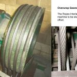
Finally, the tractive force is fully described as a value when the groove profile is established. With a µ that doesn’t change, the angle of wrap can be increased, but only to a point. In one design, the rope wraps over 270°, and the ropes interlace (Figure 3). This novel Otis long-wrap traction (LWT) design appears to introduce a slight fleet angle and the appearance of a reverse bend, both of which can have negative effects on steel-wire ropes. More accurately, fleet angle is caused by the location of the furthest rope shackle at its car hitch-point location with respect to the corresponding location of the rope groove at the machine. There will be both forward and side draw in the LWT design, and it varies from one rope to the other. Side draw causes wear of one side of the groove more than the other and leads to a reduction of available traction in the grooves. The skewing of the ropes in the LWT arrangement cause groove side wear in the sheave grooves. While it cannot be eliminated, it can be controlled. Major manufacturers have in-house limits on the amount of forward and/or side draw.
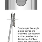
Fleet angle (Figure 4) causes a torque in a rope, winding the rope tighter on one side, and unwinding the rope on the other side. Additionally, it adds an abrasion to the sheave and rope, reducing their lives. When constructing an electric elevator, care must be taken to ensure no significant fleet angle exists.
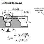
When the required traction exceeds the available traction on a U-groove sheave (for example, when you cannot increase the angle of wrap), the grooves can be modified, and the increased specific pressures provide higher available traction. The resulting extra traction has tradeoffs that go beyond this article; however, the typical grooves, their related traction formulae and their related apparent coefficients of friction are shown in Figure 5. All mechanics and technicians should have some idea of this material so that when reordering rope, basic knowledge will ensure the incorrect rope is not installed, leading to reduced rope and sheave life.
The interaction of the suspension ropes and sheave is similar in function as the rubber tire on the surface of the road; it needs to provide enough traction to prevent slipping, but not too much. (There are other suspension systems, but this article series will stay focused on traction of an electric elevator using steel-wire ropes with brief mentions of other types of suspension member designs in Part Two.)
Capstan Winch
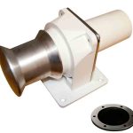
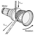
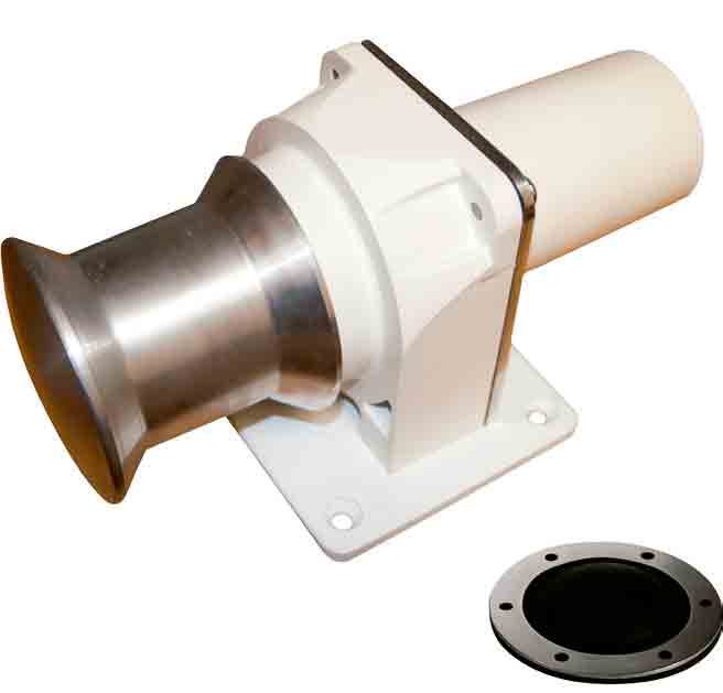
A common tool used every day by elevator personnel in construction is the capstan winch (Figure 6) that will help visualizing traction force. This makes it an ideal device, as the hands-on experience can be related to the theory. When using a capstan, the number of turns of the rope around the winch will allow a much smaller holding force to prevent the load from slipping.
The load is expressed as Tload, and the holding force is expressed as Thold. The more rope turns, the relationship between these forces changes; the increased holding force is an exponential value added to the Thold force.
The rope frictional force changes due to coefficient of friction, tension in the rope and total angle of contact. The only variable that can change is θ, the angle of wrap or the number of turns of rope on the capstan.
Tload ≤ Thold eµθ (Equation 5)
where Tload = force exerted on the rope by the load, Thold = holding force exerted on the rope by the technician, e = base of natural logarithms (2.71828), µ = static coefficient of friction between suspension rope and sheave groove, and θ = arc of contact subtended by the rope (rad).
Conclusion
Traction designs are carefully engineered, but as this article has shown, the mechanical complexities and relationships are critical to maintain the traction force and prevent loss of traction.
Any electric elevator with metal particles under a sheave requires attention: those particles are being ground off the sheave, and it is changing the traction relationship. Part Two explains which components require maintenance and testing.
Learning-Reinforcement Questions
Use the below learning-reinforcement questions to study for the Continuing Education Assessment Exam available online at www.elevatorbooks.com or on p. 153 of this issue.
♦ What is friction, and which are the different types of it?
♦ What does Coulomb’s Law of Friction enable us to do for the measurement of friction force?
♦ How is the available traction of a sheave with a round steel-wire rope found?
♦ What is considered the seminal book for determining the tractive force that will not cause slipping in elevator designs?
♦ What is normal force?
- Figure 1: All surfaces have a roughness; this depicts the surfaces interlocking.
- Figure 2: Normal force is the force perpendicular to the surface of contact, irrespective of gravity.
- Figure 3: Geared machine with 270° of overwrap
- Figure 4: Fleet angle; image courtesy of Brugg.
- Figure 5: Grooves used in the elevator industry; image courtesy of Brugg
- Figure 6: Typical capstan winch; image courtesy of Endurance Marine
- Figure 7: Wraps on the capstan winch
References
[1] Wikipedia. “Tribology” (en.wikipedia.org/wiki/Tribology).
[2] Wikipedia. “Guillaume Amontons” (en.wikipedia.org/wiki/Guillaume_Amontons).
[3] Gibson, George W. “Fred Hymans and the Theory of Rope Traction,” EW, February and March 2017.
[4] CEN EN 81-1:2004. “M.2 Traction Calculation,” “M.2.2 Evaluation of the friction factor,” “Clause M.2.2.2 Friction coefficient consideration.”
[5] Pfeifer Drako Drahtseilwerk GMBH & Co. KG. “Steel Wire Ropes in Elevators,” September 2015, p. 32.
[6] Brugg Lifting. “Steel Wire Ropes in Elevators,” 0214, 2013, p. 139.
[7] Hymans, F. and Hellborn, A.V. Der Neuzeitliche Aufzug mit Treibscheibenantrieb. Berlin, Springer Publishers, 1927.
[8] Dr. Stephen W. Attaway. “The Mechanics of Friction in Rope Rescue,” International Technical Rescue Symposium (ITRS 99).
Get more of Elevator World. Sign up for our free e-newsletter.
