Enhancing Passenger Safety: A Framework for Assessing and Optimizing Elevator Braking Distances
Oct 1, 2025

An important metric that maintenance companies can utilize to enhance equipment safety
by Shaik Javeed
This paper was presented at Elevcon 2025 in Lisbon, Portugal.
Abstract
Passenger safety is paramount in the maintenance of elevators and escalators. When a company assumes responsibility for a project, it must address various aspects related to inspections and proper maintenance protocols. It is essential, beginning with the pre-contract survey or immediately after the contract is signed, to ensure that all safety elements are functioning correctly. This diligence should be maintained during each subsequent monthly maintenance visit.
This paper aims to focus on the accurate determination of braking distances, as many lift manufacturers — except for a few — do not provide criteria for testing and verifying these distances within their controllers. This information will be beneficial for third-party elevators in independently assessing safe braking distances, thereby enhancing elevator safety.
We propose the use of rope load cells to measure and calculate the empty cabin weight and counterweight balance ratio, as this data is often unavailable to maintenance companies. These weight inputs are crucial for accurately measuring braking distances, which are derived using a tachometer wheel that contacts the main traction ropes. By assessing both maximum and minimum stopping distances, we can effectively verify the safe braking distances of the elevator.
1. Introduction
The maintenance of elevators and escalators is a cornerstone of the building services industry. Elevators play a vital role in transporting passengers across multiple levels, and without them, the movement of people within high-rise buildings would be nearly impossible. Ensuring proper maintenance is essential to guarantee that elevators operate safely and reliably.
Each year, numerous incidents — ranging from minor injuries to fatal accidents — underscore the importance of safety in elevator systems. Leading companies in the industry recognize safety not as a cost but as a core value. These organizations prioritize both occupational and passenger safety, understanding the significant physical, emotional and financial consequences that follow severe incidents.
In the context of multi-brand maintenance, tasks must be carefully assessed and technicians must receive adequate training. Technicians often face highly challenging and unpredictable conditions, which demand prompt and effective responses to ensure passenger safety. This paper focuses on one critical safety component of an elevator system: the brake. As an essential element in ensuring safe operation, the brake plays a key role in preventing accidents and safeguarding passengers.
2. How Does DIN 31051 Define Maintenance
According to DIN (Maintenance standards), maintenance is a set of measures intended to maintain the target condition of a technical system or component. It encompasses activities that aim to prevent malfunctions and failures, restore functionality and continuously improve the system’s performance.
Maintenance involves not only technical aspects but also administrative and management measures. DIN 31051 recognizes the need for proper documentation, planning and coordination of maintenance activities. This ensures that maintenance processes are organized, well-documented and aligned with the organization’s overall objectives.
There are several types of maintenance, such as breakdown maintenance, also called reactive maintenance; preventive maintenance; condition-based maintenance; time-based maintenance; and predictive maintenance.
3. Types of Maintenance
Breakdown Maintenance is maintenance work done after a failure has occurred to restore equipment to its normal working condition. The key points to take note of are unplanned, emergency-based and disruptive (can cause more downtime, not meeting contractual requirements and safety risks).
Preventive Maintenance is maintenance performed at regular intervals, regardless of equipment condition, to reduce the likelihood of breakdowns or costly repairs. The key points are that the works are scheduled and systematic, which reduces unplanned downtime, extend equipment lifespan, maintain the integrity of the installation, improve safety and reliability and reduces the need for extensive emergency repairs. It is intensive and costly if not automated. Preventive maintenance includes all measures that are carried out as part of condition-based maintenance.
Condition-Based Maintenance (CBM) is a proactive maintenance strategy where maintenance is performed only when signs of equipment deterioration or abnormal behavior are detected. Instead of relying on a schedule, it responds to real-time data from the machine itself. Or during a preventive maintenance interval, if the mechanic notices, they should immediately intervene to mitigate the risk. This minimizes the unplanned downtime and detects problems before they escalate.
Time or Usage-Based Maintenance is maintenance performed at predetermined intervals. It is routine and does not depend on the condition; is based on the prediction of the wear, reducing the risk of unexpected breakdowns; and is good for critical systems where failure is unacceptable. This can lead to higher maintenance costs.
Predictive maintenance uses machine learning or Internet of Things sensors to issue a recommendation to replace a part or perform a service on a lift or escalator before a breakdown occurs.
Based on the above maintenance types, it is recommended to apply time-based maintenance for brakes due to the reason stated above: Brakes are critical safety elements, and potential failures resulting in incidents are completely unacceptable. However, keeping in view the atmospheric conditions, one needs to be careful in selecting preventive maintenance. Predictive maintenance can also be considered, and it will take some more years for this technology to mature.
4. Examples of Brake Failures
Brake failure in elevators can occur due to both mechanical and electrical issues, as outlined below:
- a. Electrical circuit failure
- b. Wear of brake pads
- c. Rivets are coming loose on the pads
- d. Oil spillage on the brake drum leading to contamination of brake pads
- e. Plunger struck in open position
- f. Fatigue of brake parts leading to breakage of rods
- g. Poor adjustments of parts
- h. Overheating
These potential failure conditions must be thoroughly inspected during routine maintenance visits. Certain issues — particularly points b, c, d, e and f — can significantly increase the brake slipping distance, especially when the lift is brought to a stop in emergency stops or when aligning with a landing level.
In extreme cases, these failures can result in uncontrolled or unintended movement of the elevator. This risk is particularly heightened when passengers exit the cabin and the counterweight, now heavier than the remaining carload, causes the cabin to drift upward — an especially dangerous scenario that underscores the need for effective brake monitoring.
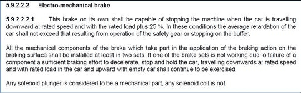
EN 81-20 (Figure 1) explains the stopping of brakes with rated load plus 25%; during no-load conditions, there is no easy way to determine and verify the braking distances; and it is of paramount importance for the engineers to infer the brake torque or slipping distances by means of a new approach.
5. Brake Testing and Validation
Elevator companies typically include detailed methodologies in their maintenance technical dossiers for testing the brake under empty cabin conditions. These procedures often specify clear criteria for conducting the test and validating whether the results meet OEM requirements. In contrast, small to medium-sized elevator companies lack such clarity in their maintenance manuals, particularly regarding the testing and validation of brake slipping performance in no-load conditions, including the verification of braking distances.
The author recognized the critical importance of evaluating braking distances, given that brakes are a fundamental safety component and a direct outcome of proper maintenance practices. Accurate assessment of braking performance not only reflects the condition of the braking system but also serves as a key indicator of overall elevator safety and reliability.
One such method involves measuring and validating brake slipping distances using two types of specialized equipment. This system utilizes rope load sensors to determine key parameters empty cabin weight, counterweight balance ratio and the car-to-weight ratio. These measured values are then input into a braking ability detector instrument, along with other relevant parameters, to accurately calculate the brake slipping distance. This approach provides a reliable and repeatable method for assessing brake performance, particularly in scenarios where manufacturer data is not readily available.
6. Product Description and Test Process
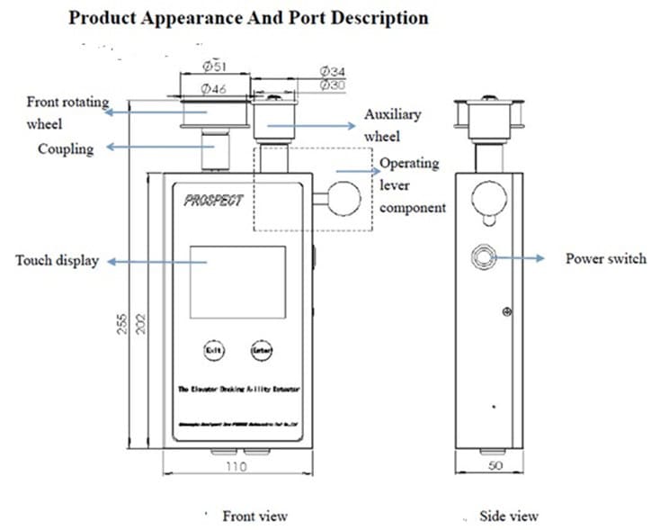
The BC100 elevator braking ability detector (Figure 2) can detect the braking ability of the elevator. The equipment consists of two parts: a handheld terminal for equipment acquisition and detection and a front rotating wheel. During inspection, the front rotating wheel is rotated close to the wire rope and the front rotating wheel is driven by the wire rope to rotate. When the elevator reaches the set stroke or rated elevator speed, the stop signal is sent to the lift controller, thereby the slipping distance of the wire rope is measured, and the test results are displayed and recorded after the elevator stops.
7. Normative Reference Documents by the Equipment Manufacturer
- GB/T 7024 terminology for elevators, escalators and moving walkways.
- GB/T 10058-2009 elevator technical conditions
- GB/T 10059-2009 elevator test methods
- GB/T 24474-2009 elevator ride quality measurement
- T/CASEI T102-2015 – China Special Equipment Inspection Standards Association
7.1 Parameter Settings
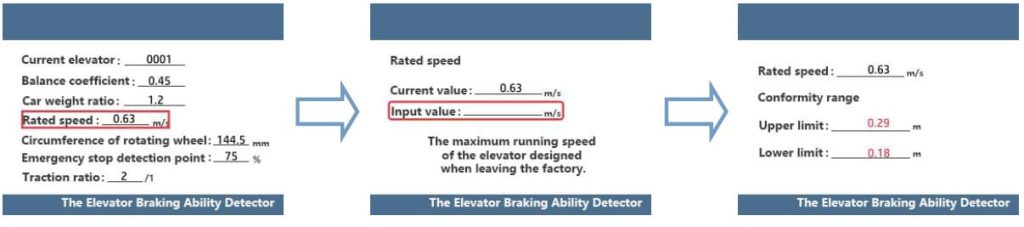
After entering the position mode, set relevant parameters (Figure 3), including the balance coefficient, the car weight ratio, the rated speed, the circumference of a rotating wheel, the emergency stop detection point and the traction ratio. in the “Rated speed” selection interface, the equipment provides nine standard speed values, and the corresponding conformity range during the setting process and the test engineer needs to pay attention to the unit of the parameter being set.
7.2 Learning Operation
Confirm the position of the elevator car (should be on the top floor) to prepare for equipment learning. In the function selection operation interface, click the “Elevator learning” button to enter the learning preparation interface, clear the displayed value (just turn the wheel manually) and then clamp the wire rope between the front wheel and the auxiliary wheel of the equipment (The angle between the equipment display screen and the wire rope is required to be 90°). Click “Start learning,” start the elevator, run to the bottom floor and the equipment begins to record the stroke of the detected elevator.
After the elevator reaches the bottom floor, click “Learning completed” to judge whether the learning process is effective based on the collected stroke data. You can select “Learn again” or “Learning completed.”
7.3 Detect Elevator Braking Distance
Confirm the position of the elevator car (should be on the bottom floor) to prepare for device detection. In the function selection operation interface, click the “Elevator detection” button to enter the detection interface, confirm that the wire rope is sandwiched between the front wheel and the auxiliary wheel (The angle between the equipment display screen and the wire rope is required to be 90°). Click “Start testing,” start the elevator again and run to the top floor.
The device will automatically output the action point based on the position of the emergency stop detection point (Note: The test engineer cannot click “Elevator stop and detection” during the detection process). After the elevator stops, click “Detection completed.”
7.4 Detection Completed
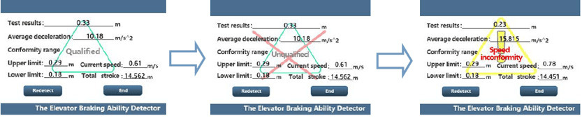
Relevant testing standards are embedded in the equipment. After completing the test operation, test conclusions are provided according to the standards: qualified, unqualified or speed conformity. The test results include conformity range, current elevator speed, total stroke, etc. (Figure 4.)
8. Additional Instruments Used To Determine the Car and Counterweight Mass
The braking ability detector instrument prompts for input of the counterbalance ratio. The car weight ratio is the carload over the car’s weight. So, to determine the dead weight of the cabin and counterweight, the author utilized a rope load detector from Henning GmbH, which provides accurate results.
9. Test Results
Three units were chosen. Two units from Mitsubishi, where we had information about the car weight and counterbalance ratio. And one unit is a foreign brand (Multi brand).
| Mitsubishi Elevator unit No. 1 – Car | Counterweight |
| Specifications: Load: 750 kg Speed: 1.75 m/s Counterweight ratio: 0.5 Roping: 1:1 Stops: 12 Car weight as per the manufacturer’s document: 999 kg Car weight measured by Henning instrument: 1084 kg 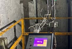 | Measured: 1431 kg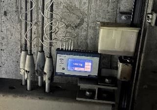 |
| Note: The additional weight of cabin tiles and car top handrails adds around 40 kg. The error is very minimal: less than 5%. | Note: Measured counterbalance ratio is close to 0.5 |
Table 1: Mitsubishi Elevator unit No. 1
| Mitsubishi elevator unit No. 2 – Car | Counterweight |
| Specifications: Load: 600 kg Speed: 1.0 m/s Counterweight ratio: 0.5 Roping: 1:1 Stops: 5 Car weight as per the manufacturer’s document: 791 kg Car weight measured through the Henning instrument: 815 kg 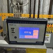 | Counterweight mass calculated as per 0.5 ratio: 1091 kg Measured: 1119 kg The difference is 28 kg, which can be additional car top balustrades. 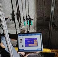 |
| Note: The error is very minimal: less than 3%. | Note: Measured counterbalance ratio is close to 0.5 |
Table 2: Mitsubishi Elevator unit No. 2
| Multibrand unit – car | Counterweight |
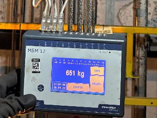 Specifications: Load: 800 kg Speed: 1.0 m/s Counterweight ratio: unknown Roping: 2:1 Stops: 5 Car weight as per the manufacturer’s document: unknown Car weight measured through Henning instrument: 651 kg x 2 = 1302 kg | 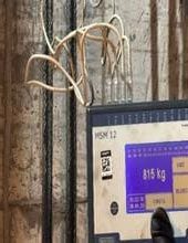 Counterweight mass calculated as per 0.5 ratio: 1702 kg Measured: 1630 kg (815X2) The difference is 72 kg, where 12 kg can be additional car top balustrades. For a 50% balance, 50 kg is required, which can be taken as an error of less than 5%, or a 45% counterbalance can also be assumed. |
| Note: Measured counterbalance ratio is close to 0.45 ~0.5. |
Table 3: Multibrand unit
The test and measurement results of the rope load meter were close to accurate, with a tolerance of less than 3%.
10. Braking Ability Checker
| Mitsubishi unit No. 1 | Test results |
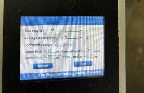 | The slipping distance is 0.89 m Rated speed: 1.75 m/s Measured speed: 1.63 m/s Min distance Lmin: 0.86 m Max distance: Lmax: 1.63 m Inference: The manufacturer’s braking distance is a bit tougher (allows less slipping distance) than this equipment. However, the values are close. |
| Mitsubishi equipment No. 2 | |
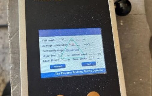 | The slipping distance is 0.59 m Rated speed: 1.0 m/s Measured speed: 0.93 m/s Min distance Lmin: 0.37 m Max distance: Lmax: 0.62 m Inference: The manufacturer-recommended slipping distance and the measured slipping distance are within the range. |
| Multibrand equipment No. 3 | Test results |
 | Slipping distance: 0.39 m Rated speed: 1.0 m/s Roping: 2:1 Measured speed: 1.06 m/s Min distance Lmin: 0.37 m Max distance: Lmax: 0.62 m Inference: The slipping distance recommended by the equipment manufacturer falls within the range. |
Table 4: Test results of the three cases
| Rated speed (m/s) | Reasonable value range of braking Distance (mts) | |
| Minimum value Lmin | Maximum value Lmax | |
| 1.00 | 0.37 | 0.62 |
| 1.75 | 0.86 | 1.63 |
Table 5: China’s special equipment inspection standards T/CASEI T102-2015
11. Conclusions
This article presents an approach for measuring the safe stopping distance of elevators — an important metric that maintenance companies can utilize to enhance equipment safety. The proposed method offers a practical solution that aligns with China’s special equipment inspection standards T/CASEI T102-2015, and the distances are tabulated for nine different speeds in the standards document. In this paper we have took the reference for two speeds. Looking ahead, this approach holds potential for further development, including the possibility of using smart devices to perform these measurements for machine-room-less models. Such advancements could eliminate the need for bulky sensors and multiple instruments, making the process more efficient and safer.
12. Acknowledgements
I would like to express my sincere gratitude to my dedicated team of engineers and technicians for their invaluable assistance in conducting the measurements with the utmost attention to safety. I also extend my appreciation to Prospect Photoelectric Tech Co., Ltd. for their support and for providing clarification on technical details during the testing phase.
References
[1] Cooper, D.A. (2021). Brake failures on lifts. 12th Symposium on Lift & Escalator Technologies. 3.1-8.
[2] Eberle, H.E. (2001). Safety First – Reliable Brakes for the latest Elevator Designs. Elevator Technology 11, Singapore 17-24.
[3] Distaso, C. (1992). The Lift brake. Elevator Technology 4, Amsterdam.

Get more of Elevator World. Sign up for our free e-newsletter.
![]()


")


![]()