Hart’s Cyclic Elevator, Part I
Apr 1, 2012

A detailed examination of Hart’s patents to achieve a better understanding of one of the first paternoster systems.
Hart’s Cyclic Elevator, designed by English consulting engineer Frederick Hart in 1877 and patented the following year (Patent No. 81, “Improvements in Elevators,” July 5, 1878), is well known by most elevator historians. This elevator is typically described as one of the first systems that eventually became known as “paternosters.” The most familiar images of this elevator are engravings produced for the July 15, 1882, issue of La Nature magazine for an article titled “Ascenseur Continu de M. Frédéric Hart.” Slightly less well known are those produced for the January 26, 1883, issue of The Engineer for an article titled “Hart’s Cyclic Elevator: Mansion House Chambers.” While their images and accompanying descriptions offer some explanation of the operation of Hart’s elevator, neither article fully explained how it actually worked. However, a comparative reading of these articles, coupled with a detailed examination of Hart’s patent permits (for the first time), will glean thorough understanding of this unique elevator’s operation.
In his patent, Hart described three designs for his proposed “continuous” elevator, which employed cages or cars that ran through parallel shafts. (It is of interest to note that the word “cyclic” does not appear in his patent.) Two of these designs were variations of an “endless chain” scheme, while the third employed a rack-and-pinion system. Both endless-chain designs utilized a similar means of carrying the cars through the shafts: Hart designed what he termed a “sling link” to connect the cars to the endless chain. Each sling link carried “a pin projecting out from it horizontally and at right angles to the plane in which the chain travels.” The pin fit into an “eye” located “centrally in the back of the cage, at the upper part,” and the car was suspended by this single connection. Two sets of rollers on the back of the car (one at the top and one at the bottom) traveled on two separate sets of angle-iron guides and ensured the car did not sway from side to side, or tilt forward or backward as it moved through the shafts. The primary differences between the two endless-chain designs concerned the designs of their respective roller systems and guide rails.
In the first design, the upper set of rollers was placed on the ends of “arms” attached to the sling link. The sling link’s pin connection permitted movement such that when the car traveled around the top or bottom of the endless-chain circuit, the arms pivoted, which allowed the rollers to follow the curving path of the guides. The lower rollers were fixed in place and traveled along vertical guides that ended near the top and bottom of the shaft at the points where the car began to move through the curved sections of the upper roller guides. The movement of the car’s lower half was stabilized by modified gear wheels placed below the chain gears (located at the top and bottom of the shaft). The secondary gear wheels were connected to their corresponding chain gear such that each pair of gears “moved in unison.” As the car traveled around the top or bottom of the shaft, the secondary gear wheels engaged a “strong stud” that was centered between the lower rollers on the back of the car; thus, the car was held securely in place as it transitioned between shafts.
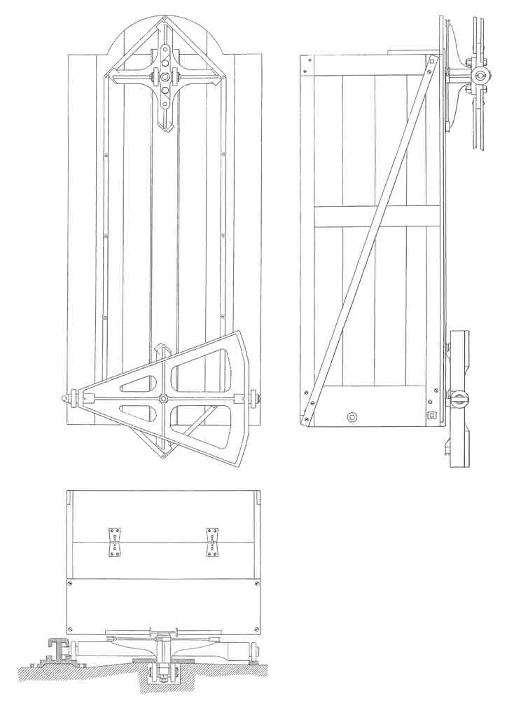
Hart’s second endless-chain design employed a variation of the upper roller scheme in which, while the rollers were still attached to “arms,” the rollers were placed immediately adjacent to the sling link pin/eye connection. The upper rollers traveled in narrow-angle iron guides centered behind the car. In this design, the lower rollers were also placed on a pivoting armature; however, unlike the centered upper rollers, these were located near the outer edge of the car. The lower armature was linked to the upper roller arms, which extended out from the sling link, such that the two sets of rollers pivoted in unison as the car traveled along the curving guide rails at the top and bottom of the shaft. This arrangement required a unique set of guide rails for the lower rollers: an outer rail that extended from edge to edge of the parallel shafts and which described a wide arc at the top and bottom, and an inner rail centered between the shafts. The end of the armature holding the inner lower roller (which ran on the center guide rail), featured a “stud” at the end that ran inside a semi-closed section of the guide rail. The stud facilitated the car’s smooth transition as it moved from one shaft to the other.
The third design described by Hart featured racks centered along the car’s top, bottom and sides that meshed with gear wheels located at set intervals throughout the shaft. The gear wheels were powered by vertical drive shafts with beveled gear connections. As the wheels turned, the cars were propelled up or down. The car’s transfer from one shaft to the other required a somewhat complicated arrangement:
“When the cage approaches its upmost position, pins or round teeth at the corners of the cage enter between the teeth of the wheels, and the cage hangs by these pins, and is raised and carried laterally by them until it gets to the top. At this point, the wheels, still revolving, come into gear with racks fixed across the bottom and top of the cage, and so the cage is traversed from side to side until pins at its other corners (which form the terminal teeth of the horizontal racks at the top and bottom) engage with the teeth of the wheels, and then hanging from the wheels by these pins, the cage is carried sideways and at the same time lowered until the teeth of the wheels on the axis, which is then level with the bottom of the cage, begin to gear into the racks upon the cage side.”
Hart’s decision to describe several variations of his invention was a common tactic employed by inventors in the 19th century. However, this strategy often causes problems for historians trying to determine how an elevator actually worked: i.e., which design represented the built version of the machine? In this case, as will be seen, there is no question that Hart’s second endless chain design was the primary basis for the cyclic elevators manufactured in the 1880s.
Although the precise nature of their business relationship remains unknown, in 1878, Hart reached an agreement with J. & E. Hall of Dartford to build what they marketed as “Hart’s Cyclic Elevator.” The speed with which the elevator was brought to the public’s attention is interesting: Hart’s patent was awarded on July 5, 1878, and approximately four months later, Hall launched the advertising campaign. The November 15, 1878, issue of the Building News and Engineering Journal featured a large illustrated advertisement that included the following copy: “Hart’s Patent Cyclic Elevator, Apply to the Patentee 37, Walbrook, E.C. or to the Sole Makers: J. & E. Hall, Engineers, Millwrights, Founders, and Boiler Makers, Dartford, Kent.”
While illustrated advertisements in architectural or engineering journals were not unusual in the late 1870s, they were still more the exception than the rule due to their additional cost. Hall’s belief in the commercial viability of Hart’s elevator is indicated both by the size of the advertisement and the fact it continued to run in the Building News and Engineering Journal for the next two years. The drawing, with its depiction of men and women riding up and down, was clearly intended to sell the “idea” of the cyclic elevator. Unfortunately, it provided no detailed information about the elevator’s mechanical operation. Nonetheless, this early drawing captures the perceived potential of Hart’s design. Part Two of this article will continue this investigation and includes a detailed examination of the first two cyclic elevators built by J. & E. Hall.

Endless Chain Design (l-r) No. 1 and No. 2; from Frederick Hart’s patent “Improvements in Elevators” (July 5, 1878) 
Side elevation and plan of car designed for Endless Chain Design No. 1; from Hart’s patent “Improvements in Elevators” (July 5, 1878) 
Side elevation, rear elevation and plan of car designed for Endless Chain Design No. 2; from Hart’s patent “Improvements in Elevators” (July 5, 1878) 
Advertisement from Building News and Engineering Journal, November 15, 1878
Get more of Elevator World. Sign up for our free e-newsletter.


