19th-Century Elevator Guides and Guide Rails
Nov 1, 2014

The patent-filled early history of how these important components came into their own
The design of elevator guides and guide rails was among the first critical problems identified by inventors of the passenger elevator in the 19th century. Elisha Graves Otis’ safety device (designed in 1854 and patented in 1860) was predicated on the use of a unique guide rail featuring ratchets or teeth that engaged pawls or “safety dogs.” In 1866, Otis Tufts, inventor of the Vertical Railway Elevator, offered the following observations on this aspect of elevator design:
“The usual line of motion of [the] elevator car is substantially vertical, it hanging freely suspended between slides or ways, which, being affixed to the walls and partitions of buildings, are not capable, in practical use, of perfect adjustment, being liable to disturbance of position, consequent upon the shrinkage of timbers, settling of foundations, etc., so that if the guides or cross-heads of the car fit closely to the slides or ways, sticking and binding will occur, accompanied with disagreeable noises and loss of power; and if the guides or cross-heads but loosely embrace the slides or ways, then the swinging of the car will annoy its passengers, and the noise consequent upon the striking of the car in its vibrations against the slides will annoy the occupants of the building, as well as the car passengers.”
Tufts’ observations effectively outlined the key aspects of this problem and established the context for design solutions proposed and utilized in the late 1800s. And, while guides and guide rails were often addressed within the design of a complete elevator system, patent records reveal they were also the subjects of focused design efforts.
The source of Tufts’ observations was his 1866 “Improvement in Elevator Guides” (U.S. Patent No. 60,443). In it, he referred to the guide rails as “slides” or “ways” that were “provided with ratchet teeth, which, in connection with spring pawls or catches, may be made to serve as a safety apparatus to prevent the car from falling, in case of the breakage of the hoisting ropes or chains.” It was not unusual at this time for elevators to incorporate a variation of Otis’ safety device into their designs. However, Tufts set the ratchet into a wooden guide rail and proposed the use of roller guides, “made as wheels,” to direct the motion of the car (Figures 1 and 2). He stated the rollers could be constructed as solid metal wheels fitted with “a band or ring of vulcanized rubber, the elasticity of which causes it to pass easily over any irregularities in the ways.” This design was perceived as being “sufficient in all ordinary cases to insure constant and noiseless contact.” He also proposed an alternative roller construction that used “leather disks clamped between metallic disks.” In this system, the leather disks could be replaced by other “suitable materials,” such as “wood, paper or green hide.” The goal was to provide a smooth ride and prevent “the sound which arises from the motion of a metallic wheel over a metallic rail.”
In January 1873, Charles Otis received a patent for “Improvements in Guides for Elevators” (U.S. Patent No. 134,698), which was a variation on Tufts’ design. The key difference was the use of metal guide wheels attached to U-shaped arms, which ran on guide rails that featured “a strip of leather” or similar material that had “a like soft or elastic surface.” The strip of leather was “glued, cemented or otherwise secured” to the surface of the wooden rail (Figure 4). Charles Otis claimed the “guide-rollers, working. . . upon the soft or elastic surfaces provided upon the guide rails, will be practically noiseless in their operation, any inequalities in the relative positions of the rollers and surfaces being nullified or compensated for by the yielding nature of the leather.”
Lorenzo Graves’ 1878 “Improvement in Ratcheted Guide for Elevators” (U.S. Patent No. 206,434) provided additional insights into the rationale behind designs that enclosed the metal safety ratchet within a wooden guide rail:
“The cast-iron ratchets, when used as guides, do not make a smooth or even surface or track for the platform or car to run upon, being more or less warped or bent, and varying in thickness. To obviate this difficulty, they have sometimes been planed to a smooth surface and uniform thickness. This was expensive and could only be adopted for the higher-priced passenger elevators. Hard woods have also been used for the guides or tracks, which, though noiseless and smooth, were nevertheless objectionable, because they lacked the essential element of safety found in the ratcheted guides. By [encasing] the iron ratchets in or between the wood by the flanges on the iron. . . and the wood screwed to the guide-posts or to the walls of the hatchway, the wood will so hold, strengthen and retain the iron [such] that, if the latter should be broken, it could not separate from the wood or become displaced.”
Graves’ patent concerned “the employment of a wooden casing for the metallic ratchet-bars,” which he claimed would also “serve as a noiseless guide for the shoes of the car or platform to move upon.” While this feature had been included in earlier patents, it had not been previously claimed as an original design feature.
A new guide-rail design was featured in Charles Otis’ 1885 patent, “Chair for Elevator Guide-Posts” (U.S. Patent No. 310,713). The patent’s primary focus was an improved “chair” or adjustable clamping system used to attach the guide rails to the wooden beams of the shaft. Charles Otis reported:
“It is a well-known fact that the hoistways of elevators are apt to get out of shape, owing to the warping and springing of the timbers forming the hoistways, or from other causes. When the hoistways are thus thrown out of shape, the guide-posts are usually thrown out of line with each other, and also distorted, which causes the elevator-car to bind. On such an occurrence, it requires considerable time to line up the guide-posts.”
Charles Otis claimed his design permitted easy “side adjustment” of the guide rail, and, “if necessary, the U-shaped support” allowed “inward or outward adjustment.” His chair design held a unique guide-post rail made of “ordinary iron or steel rails secured together end to end.” The profile of the guide rail depicted in the patent drawing resembles a rail used on a typical train track (Figure 4). This patent is one the first that depicts an iron or steel rail that did not include safety ratchets.
Charles Otis’ proposed use of an all-metal guide rail was also unusual. In fact, the majority of guide rail patents from the late 1880s and early 1890s featured wooden guide-rail systems without an iron safety ratchet (which had slowly fallen out of favor as a preferred safety device). Graves’ 1888 “Elevator Guide” (U.S. Patent No. 394,768) depicted a solid wood guide rail embraced on three sides by his improved guides, which employed a series of springs that allowed flat guide shoes to flex and move as they traveled along the rail (Figure 5).
The use of cylindrical or tubular metal posts that carried wooden guide rails had apparently become popular by the mid 1890s. In 1895, Martin Christopherson patented a “Guide-Post Clamping Device for Elevators” (U.S. Patent No. 532,414). He noted the wooden “guide strips” were “usually secured in any convenient manner to tubular guide-posts,” which were “made in sections of a length corresponding to the distance from one floor of a building to another, and at each floor, these sections [were] secured to a transversely arranged beam” (Figure 6).
Christopherson’s patent was one of the first to depict the use of steel I-beams in the shaft, reflecting changes in building construction associated with the rise of the skyscraper. He also observed:
“The customary manner of fastening the I-beams to the guide posts is to drill holes in the flanges of the beams, and similar holes in projections or lugs from the guide posts, and then clamp the posts to the beams. . . . Such a construction is comparatively expensive and troublesome, because it frequently happens that the guide-posts and strips must be adjusted in position in the elevator hatchway or well and that such adjustment throws the holes out of alignment, and, consequently, new holes must be formed for the bolts.”
Christopherson’s clamping system allegedly permitted easy adjustment of the guide posts as needed.
Francis Bates’ 1899 “Elevator-Guide” (U.S. Patent No. 622,792) also employed tubular guide rails. However, he omitted the wooden guide strips and proposed using a solid metal guide rail (Figure 7). His patent text provides interesting insights into the differences between freight and passenger guide-rail design:
“I am aware that hollow pipes or tubes have been used for the guiding of freight elevators for building purposes, carrying bricks, mortar, etc.; but for the purpose of guiding passenger elevators, where the slightest grating or jarring noise is objectionable on account of the annoyance to timid and nervous persons riding in the elevator car, as well as to those occupying rooms adjacent to the elevator well, such pipes or tubes are not only objectionable, but their use would be positively prohibited, owing to the reverberations of such hollow bodies and the ringing and scraping sounds produced by the guiding shoes of the passing car, owing to the resonant qualities of pipes or tubes.”
Bates claimed his use of solid metal tubes had the following advantages: they had a “greater stiffness at a greatly reduced weight, thus cheapening first cost and transportation,” “a much larger wearing-surface,” were “easier to handle and erect,” were “non-resonant under the rubbing of the car-guides,” and they required “less bolting to the elevator well.”
A more normative approach toward metal guide-rail design was proposed by George Reynolds in his 1896 “Elevator-Guide” (U.S. Patent No. 559,539). He noted, “Heretofore where metallic guides have been used for guiding the cage of an elevator, it has been common to make use of an ordinary bar of merchant T-iron.” However, this shape had “proved to be objectionable, because in course of time, from wear,” it formed distinct “shoulders” due to the gradual wearing of the web’s thickness due to the action of the guides. This increased “the friction with the guide-piece upon the cage,” limited “the play of the cage laterally” and “weakened the web of the rail.” Reynolds proposed to use rails in which “the head of the web is thickened toward the outer edge, being of normal thickness at its junction with the flanges or base portion” (Figure 8). The sides of the “thickened portion” of the web could be “machined or planed down to the requisite extent to get the desired thickness and parallelism, so as to receive the faces of the usual clamps without unduly weakening the web.” In 1896, Godfrey Rebmann patented a guide rail that resembled Reynolds’ design and featured a narrow neck and vertical grooves in the steel T-shaped rail (Figure 9).
The design of guides and guide rails in the 19th century also prompted the development of additional devices aimed at ensuring the smooth travel of cars. These systems included automatic guide-rail oilers or lubricators. The first lubricating system was patented in 1888, and, thus far, eight additional 19th-century patents have been found. A future article will explore these early designs, as well as the increased interest in these systems during the first quarter of the 20th century. (Thus far, 50 patents for lubricating systems have been identified for the years 1900-1925). The efforts of the inventors and designers of the first elevator guides and guide rails – from Tufts’ improvements on Elisha Graves Otis’ ratchet system to Reynolds’ improved T-shaped guide rail – reflect the ingenuity of these individuals and provide additional insights into the manufacture, construction and operation of early elevators.

Figure 1: Otis Tufts, “Improvement in Elevator Guides” 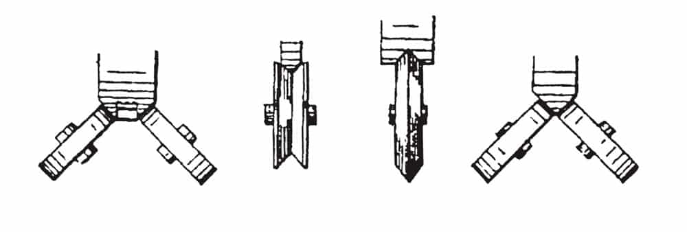
Figure 2: Tufts, “Improvement in Elevator Guides”: “Variations on Guide Wheel Design and Placement” 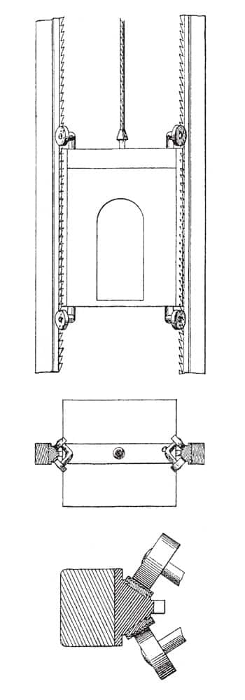
Figure 3: Charles R. Otis, “Improvements in Guides for Elevators” 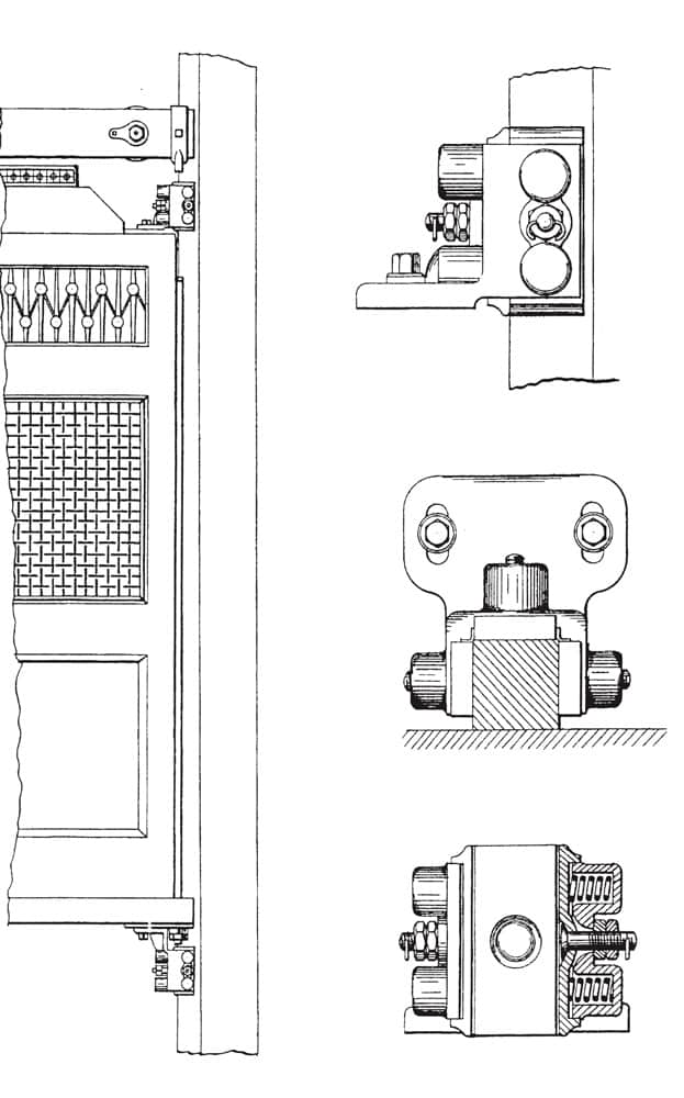
Figure 5: Lorenzo S. Graves, “Elevator Guide” 
Figure 6: Martin Christopherson, “Guide-Post Clamping Device for Elevators” 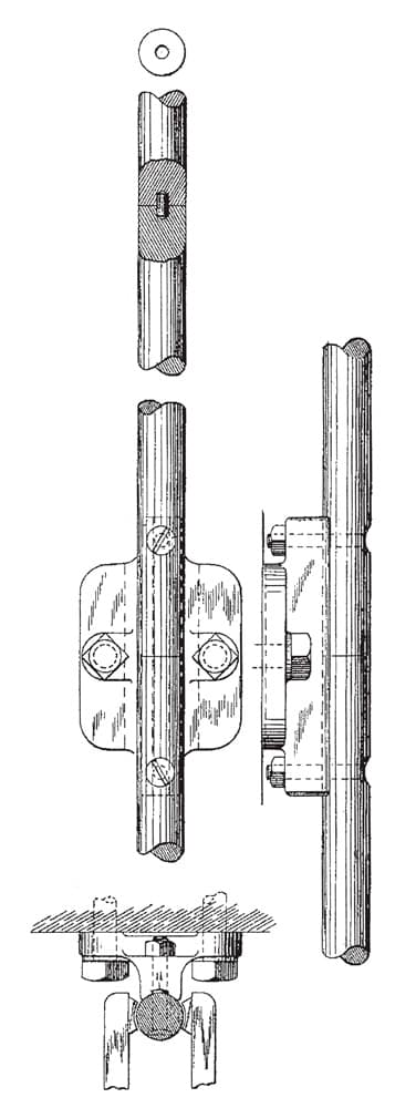
Figure 7: Francis A. Bates, “Elevator-Guide” 
Figure 8: George H. Reynolds, “Elevator-Guide”: (l-r) “Merchant T-Iron Rail,” “Merchant T-iron Rail Showing Web-Wear Due to Use” and “Reynolds’ Improved Rail Design” 
Figure 9: Godfrey R. Rebmann, “Elevator Guide”
Get more of Elevator World. Sign up for our free e-newsletter.


