An examination of new requirements to A17.1/B44 for door protection and how the new mandatory devices work
Improving the safety of elevators and escalators has been the primary goal of code writers since the 1890s. The first national code was published in 1921, and its first revision, in 1925, included, “The purpose of this code is to provide reasonable safety for life and limb. The code changes recognized changing technologies, addressed aging equipment and recognized specific known hazards. This article explains the hazards surrounding closing hoistway and car doors that have again been addressed in the ASME A17.1-2019/CSA B44-19 Safety Code for Elevators and Escalators.
Closing elevator doors can cause injury to persons when impacted by moving hoistway-door panels, particularly the leading edge of the closing door, when entering and exiting an elevator. Door-related incidents were estimated to be more than 40% of all elevator-related injuries in 1989, specifically being impacted by the hoistway door:
“A good starting point is a review of the major product liability exposures relating to passenger elevators. It is estimated that 85% of all alleged elevator accidents occur in the entranceway, approximately evenly divided between door-impact incidents and those related to the stopping inaccuracy of the car relative to the hoistway sill.”[1]
In your author’s 11-year consulting practice in the forensic arena, “door-impact” injuries are 21% of the total of all injuries, with “trip and fall” and “sudden stop” injuries being 38%, and “other” injuries being 41%. This indicates there has been a decrease in door-strike injuries, likely due to the replacement of mechanical door reopening devices with 2D, infrared reopening devices throughout the last 30 years.
In the new, 22nd edition of ASME A17.1-2019/CSA B44-19 Safety Code for Elevators and Escalators, requirements were added to assist in the reduction of door-strike injuries, as 3D door-reopening-device technology has been fully developed, tested and made available. 3D door-reopening devices are mandatory in this edition of the code, and this change is a welcome addition to hazard reduction.
| Learning Objectives |
After reading this article, you should have learned that:♦ A significant percentage of elevator-related injuries occurs at the doors. ♦ A17.1/B44 addresses real-life issues with real-life solutions. ♦ The 2019 edition of code requires 3D door protection. ♦ The 3D systems must sense their ability to operate correctly and provide feedback to the controller. ♦ 2D detection is required (in addition to the 3D detection). |
Background
To evaluate opportunities to reduce door-impact incidents, in 1997, the ASME A17 Standards Committee created the Ad Hoc Committee on Door Protection to review the hazards and examine the products available in the marketplace and the state-of-the-art technologies. A17 was to develop code requirements to increase safety based on the review. The committee met many times from 2008 to 2019, inviting vendors to participate, provide data and ultimately contribute their knowledge of the performance abilities of the products. The requirements were written with full assistance of the vendors, and the requirements were specifically based on all products’ ability to comply with them. The committee will remain working on important issues regarding certification and reliability issues.
The committee work first focused efforts from 1997 until 2008 on vertically sliding door systems used on freight elevators, culminating in requirements for complete 2D reopening coverage of the freight-door entrance.
These requirements were first published in A17.1a-2008/B44a-08. Freight-door incidents were virtually eliminated after the introduction of these protections. The next work focused on 3D protection of horizontally sliding passenger elevator door systems. It will reduce user contact with the moving doors, while minimizing nuisance re-openings. To ensure the devices remain operative, requirements will consider the two main types of 3D protection: door- and transom-mounted solutions.
Hazard assessment identified corrective actions, including a review of available door-protection technology. The language approved for publication, along with the rationale provided for reference, are the subjects of this article. Of most importance, the hazard assessment and experience identified the leading edge of the closing hoistway door as the area of concern and to which much of the emphasis of protection is designed to protect against impact. Crushing (being squeezed by the closing door) was also considered by the new language.
The 2019 edition of A17.1/B44 was issued in December 2019 with an effectivity date of June 30, 2020. This means requirements could take effect as early as spring 2020 in jurisdictions that automatically adopt the code. This timeframe will be later for other jurisdictions that will adopt the 2019 edition of the code. In the U.S. and Canada, the adoption of the code in a jurisdiction is often delayed, sometimes for years. Offsetting this delay in code adoption is the tendency for the major manufacturing companies to provide products compliant with the latest code, regardless of the jurisdictionally adopted code, to reduce their risk. New elevator orders will likely be provided with 3D door protection, unless the buyer excludes it due to the extra cost. For the existing installation market, there are, as yet, no mandatory code requirements; 3D protection could be bought and sold today. By being first to market with a tagline like “Compliant with the New 3D Door Requirements,” manufacturers could establish their offer of this product as a market leader.
Design and Testing of a “Detection Means of Approaching Objects”
The new design requirements are in A17.1-2019/B44-19, Requirement 2.13.5. There are specific minimum target sizes; they are illustrated in Nonmandatory Appendix S, and this article includes illustrations of the 3D requirements. The specific moving target size to be detected are cylinders 200 mm (8 in.) in diameter that are 1,000 mm (40 in.) tall. The 3D system must detect targets that are flat black and glossy white. Federal Standard 595C defines the colors: for flat black, it must be within the color range of 37005-37050. For glossy white, the color range is 17800-17999.
This target cylinder must be moving toward the doors. Targets not approaching are not required to be detected. The illustration in A17.1/B44, Nonmandatory Appendix S shows three cylinders, which simply represent three positions where a cylindrical target must be detected. This simulates a child approaching and entering the detection zone. The cylinders must be detected at any approaching speed up to 1 m/s (3 ft/s) anywhere between 500 mm (20 in.) and 225 mm (9 in.) from the landing-side face of the hoistway door and 225 mm (9 in.) ahead
of the leading edge. The cylindrical targets may also be detected prior to the defined zones. To be clear, if the approaching object is moving at greater than 1 m/s (3 ft/s), it is not required (or necessarily possible) to sense and reopen the doors.
Approaching-object detection means must be effective until the leading edge of the doors are within 450 mm (18 in.) of the fully closed position and are permitted to be effective up to the fully closed position. The allowance to exclude this dimension had more to do with the door-mounted solutions being unable to see the leading edge of the door, and so eliminate the false reopening as the strike of a side-opening door or the other door of a center-opening door system is detected, causing a false reopening. Transom-mounted systems can typically remain effective until very near full door close.
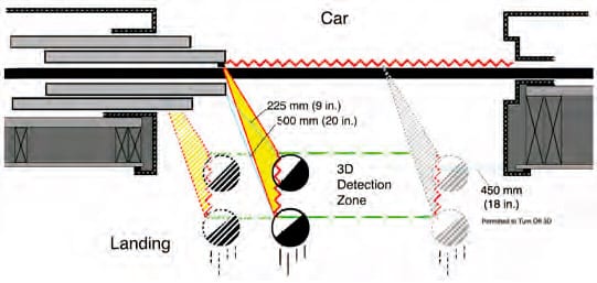
The detection zones are illustrated in Figures 1-4 to assist in visualizing the requirements. The essential safety is shown as the zones of detection as required by code language. Figures 1 and 2 show a door-mounted solution. The yellow area represents light emitted from a door edge, moving with the door panel, extending up from the bottom of the door panel to typically a minimum of 1,675 mm (66 in.) high. The critical area is the 3D detection zone, shown bounded by green dotted lines and vertically up to 1,000 mm (40 in.) from the floor. Detection of approaching objects must occur and cause the doors to stop and reopen when a target enters somewhere in this zone. The leading edge of the hoistway door on the landing side must be a minimum of 225 mm (9 in.) from the approaching object moving up to 1 m/s (3 ft/s). With these systems, the light is reflected either to the same device that transmitted it or to the partner device on the strike or other door panel.
The multiple cylinders in Figure 1 are shown in different locations to represent detection when the door was fully open, then closing, then relatively where the reopening device is permitted to turn off. The 225 mm (9 in.) and 500 mm (20 in.) are perpendicular to the face of the door panel (drawings not to scale). The cylinders are shown moving toward the car at up to 1 m/s (3 ft/s) and represent one cylinder that has moved from the start to the end of the 3D detection zone. The grayed-out cylinders represent where the detectors are permitted to be disabled and not have to detect. The red zigzagging lines represent the mandatory areas of detection relative to the closing door. The 2D reopening device is still required in all cases.
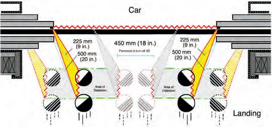
Figure 2 shows a center-opening door system while closing and assumes the 3D detector is incorporated on the car doors. There are now two hoistway-door leading edges to monitor; therefore, two black cylinders represent targets walking toward either leading edge. The multiple cylinders are in different locations to show a representation of detection when the door is fully opening and starting to close, and while the door is closing. The 225 mm (9 in.) and 500 mm (20 in.) are perpendicular to the face of the door panels.
The target cylinders are again shown moving toward the car at up to 1 m/s (3 ft/s) and represent a cylinder that has moved from the beginning to the end of the detection zone. The grayed-out cylinders represent where they are no longer required to be detected. The red zigzagging lines represent the mandatory areas of detection relative to the closing door. The 2D reopening device is still required in all cases.
The 3D detector is permitted to turn off when the door panels get within 450 mm (18 in.) of fully closed. There is likely a shaded area for some door-mounted detectors, though this would not be the case for transom-mounted systems, as most transom devices will be operative as the doors close to less than 200 mm (8 in.). This allowance to disable the detector is based on the geometry of photonic travel, combined with the time when a moving door is nearly closed, reducing the risk of door-panel leading-edge impact danger.
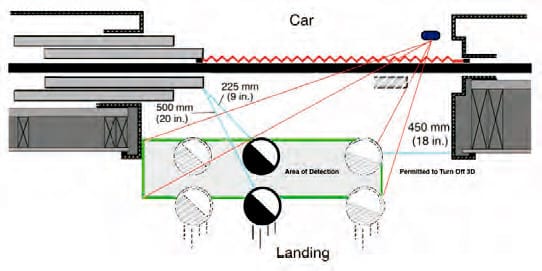
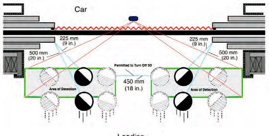
Figures 3 and 4 are like Figures 1 and 2, except these are drawn with the detector device mounted on the car transom (in a stationary location, instead of moving with the door panel). The detection zone is the same; the illustrations show where a target must be detected.
Other requirements describe that the means to detect must annunciate if it has failed, and it can render itself inoperative after 15 s to allow false detections to be ignored so elevator service will continue, provided the door-closing energy is reduced. Most importantly, it must notice its ability to detect the targets before the start of the next door close. If it is unable to detect its own failure, the door system must go into a low-energy close (nudging) operation.
The cylinders in Figures 1-4 are drawn with white and black halves to indicate that the system must detect both a glossy white target and a flat black target. Not shown is a side view of the detection zone and targets; however, the detection does not require the full target to be in the detection zone; any portion of the target must be detected when it enters the detection
zone. The cylinders are 1,000 mm (40 in.) tall by code requirement. To simulate a child’s height, however, the first entry of the target into the detection zone can be used to reopen the doors. By the time the target is within 225 mm (9 in.) from the leading edge, it must be detected, and the door must reopen.
Field Testing and Inspection of a Detection Means of Approaching Objects
Separate from design testing, the addition to the ASME A17.2 Guide for Inspection of Elevators, Escalators, and Moving Walks defines what in installed systems will be field tested and inspected. The 3D detection device is referred to as a “means” to differentiate it as a performance requirement and not prescribe it to be any specific kind of device. Then, the requirements are written in performance language, the thing the “means” is required to accomplish. Inspecting it in the field involves simply walking toward the closing doors at a normal pace and not being impacted by the door panel. When the doors are less than 450 mm (18 in.) from the fully closed position or 20 s after initial detection, the means is permitted to be rendered inoperative, provided the door closing speed is reduced to nudging speed to reduce the kinetic energy. Reopening is described as the doors having stopped moving, and they must reopen a minimum of 915 mm (36 in.) and/or fully open. After a timeout, the doors can close but at reduced energy levels.
The test simply describes a person who is walking toward the closing door. They must be detected when within the area of detection and moving toward the moving leading edge. The mandatory detection zone was selected after interviewing
all detector companies, then shaping this area to ensure all companies could comply with their products. The supplier companies that participated in the work reached consensus on the objects and the areas.
| Learning-Reinforcement Questions |
| Use the below learning-reinforcement questions to study for the Continuing Education Assessment Exam available online at elevatorbooks.com or on p. 126 of this issue. ♦ What prompted the A17 Standards Committee to create a committee to review the hazards and examine the products available in the marketplace and the state-of-the-art technologies involving door safety? ♦ How has the percentage of elevator-related injuries involving doors changed over the years? What are some reasons for this to have occurred? ♦ What are the advantages of 3D door-protection devices, and how will their installation change door operation and the elevator market? ♦ What are the code requirements for detecting targets in the 2D plane? ♦ What must the detection system self-check to ensure the detection system is operational? ♦ Why would a 3D door detector render itself inoperative after 15 s to allow false detections to be ignored? ♦ Why would a 3D door detector go into a low-energy close (nudging) operation? ♦ What is the condition under which doors are permitted to close in the event the detection system fails? ♦ How is the 3D detection device referenced in the addition to the ASME A17.2 Guide for Inspection of Elevators, Escalators, and Moving Walks on which this article focuses? |
Design and Testing of “Objects in the Door Path”
The design requirements for 2D reopening devices are also in Requirement 2.13.5. For the first time in A17.1/B44, the code has defined minimum target sizes of what a 2D reopening device must detect. The requirements describe “prisms,” the geometric word for a 3D object. It is defined as a solid figure with two end faces that are similar, equal and parallel rectilinear figures, the sides of which are parallelograms. In addition to the sizes and colors, the new requirements define the areas where detection must take place. The prisms must be 80 mm (3.15 in.) by 50 mm (2 in.) with one target painted flat black and another target painted glossy white. These colors are also defined in the Federal Standard 595C.
Operational Status
Other requirements describe that the detection means sends a signal to the door or elevator controller that it is working properly (a self-monitoring feature). This can be a dry contact or serial communication to the door operator of the elevator controller but requires that, if the detection means cannot detect the required objects, it must cause kinetic energies to be reduced to the door panel(s) to an instantaneous value not exceeding 8 J (6 ft-lbf) or an average value not exceeding 3.5 J (2.5 ft-lbf), what is known as “nudging operation.” The detection means must be checked prior to a fully open door closing.
The new requirements are a tremendous improvement in the safety of those most vulnerable to hoistway-door impact. These types of injuries are wholly preventable with the addition of this technology that has been available for more than 20 years. The improvement in these technologies is substantial and why the code could and did consider making these devices required.
We should:
- Make efforts to encourage owners to reduce their risk of door-impact incidents
- Share the code change with fellow industry personnel
- Continue to verify the door force with a force gauge (still required)
- Continue to verify the door-close time with a stopwatch Elevator companies should:
- Train mechanics to understand the importance of door hazards and mitigations
- Provide the tools and training to each route mechanic, particularly on 3D devices
References
[1] Gibson, George W. “Kinetic Energy of Passenger Elevator Door
Systems,” ELEVATOR WORLD, December 1989.

Get more of Elevator World. Sign up for our free e-newsletter.