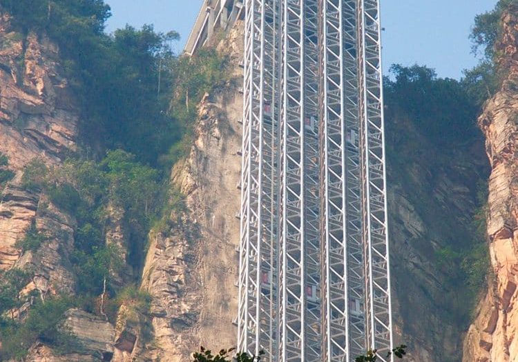
A 1902 Warner Hydraulic Elevator
Oct 1, 2014

bHistoric horizontal hydraulic freight elevator had innovative solution to fire safety and shaft design.
The size, material characteristics and durability of 19th-century elevator engines often result in a literal “presence of the past,” with the very real prospect of “discovering” old elevator engines “hiding” in basements and penthouses. When these engines are found, they provide a unique opportunity to understand how such early systems worked and how their installations often differed dramatically from the ideal conditions depicted in advertising materials. These opportunities also occasionally lead to the discovery of previously unknown elevator-related systems. The recent exploration of a 1902 Warner horizontal hydraulic freight elevator yielded all these outcomes. The following account describes this elevator and a previously unknown and innovative solution to fire safety and shaft design.
The setting for this elevator is the Golden Rule Co. Building in Belington, West Virginia. The building was constructed in 1902 for Valley Grocery Co., which was founded the same year by Luther P. Shinn (b. 1850), Hugh B. Shinn (1874-1950) and G.W. Shipman. In 1929, the business was reorganized and rechristened Golden Rule Co., which offered patrons an expanded range of products. The building is a three-story brick structure with a full basement, and its interior configuration indicates it was originally designed to accommodate a freight elevator. The elevator is located near the center of the building, and the system appears to consist of an intriguing blend of features and components from at least two generations of Warner hydraulic machines.
Warner Elevator Manufacturing Co. was one of a number of regional companies that thrived in Cincinnati during the last quarter of the 19th century and the first part of the 20th century. (For more on this context, see “The Elevator Industry in Cincinnati: 1860-1900,” ELEVATOR WORLD, August and September 2008.) Company founder Warren Warner claimed to have built the first hydraulic elevator in Cincinnati, and by the early 1880s, his product line included a horizontal pull machine designed for freight and passenger use. In the early 1890s, he introduced an improved version of this machine that featured a new piping design and new safety features. The promotional images produced for these machines (dated 1884 and 1893) depicted their use as freight elevators (Figures 1 and 2). This fact allows these images to be used as a critical means of evaluating the Golden Rule elevator.
The primary differences between the two published images include the location of the control valve, the supply/discharge piping arrangement, the traveling sheave carriage design and the car design. In the 1884 engraving, the control valve is located near the bottom of the shaft and placed in a vertical position. By the early 1890s, the valve had a new horizontal orientation and had been moved away from the shaft and placed near the end of the hydraulic cylinder. The new piping arrangement found in the 1893 engraving was a direct response to problems encountered in the use of hydraulic elevators. It was not unusual for city-water supplies to have substantial amounts of air trapped in their water, and it was necessary to provide a means to catch and release this air. The vertical pipe adjacent to the control valve (which continues above the horizontal connection to the water meter) might have been intended to serve this purpose, with the air released by an air cock.
The 1884 traveling sheave carriage employed two arms (one on either side of the carriage) that extended from the center of the sheave carriage toward the cylinder and which supported two guide wheels that traveled between the round horizontal support bars. The 1893 carriage employed four guide wheels (two per side), located on arms that extended in both directions from the center of the traveling sheave assembly (Figure 3). This ensured the stable passage of the carriage as it moved along the track. Additionally, the 1884 elevator used a typical open-platform car with a simple connection between the hoisting rope and crossbeam, while the 1893 car was semi enclosed, featured a more elaborate cable connection and employed Warner’s patented safety gate (Figure 4).
Warner had patented the safety gate design in 1884: “Automatic Hatch-Closer,” U.S. Patent No. 304,381 (September 2, 1884); thus, it is interesting that it was not included in the 1884 engraving. The piping system and automatic shutoff found in the 1893 engraving (the thin diagonal and vertical arm assembly located right of the control valve) also closely resemble the elevator system patented by Charles H.M. Atkins in 1893: “Hydraulic Elevator,” U.S. Patent No. 508,159 (November 7, 1893) (Figure 5). Atkins was Warner’s grandson, and, after serving as secretary and treasurer, he became company president following Warner’s death in 1891. The patent text echoes the design changes cited above; Atkins noted that the “well known Warner valve” was now “turned upon its side,” instead of being used in its former vertical orientation. The large pipe attached to the top of the cylinder end served as both the water supply and exhaust pipe for the engine. Atkins employed a large-diameter pipe “so that each time the cylinder is exhausted, the air which accumulates in the top of the cylinder will be carried off with the exhaust water.” The smaller pipe (beneath the supply/exhaust pipe) was designed “for the purpose of freeing the cylinder from any sediment.”
The Golden Rule elevator engine appears to employ features from both the 1884 and 1893 designs. The piping system resembles that found in the 1893 engraving and in Atkins’ patent; however, its installation — with the exhaust pipe traveling upward and back across the engine — serves as a reminder of the challenges presented in actual installations (Figures 6 and 7). The traveling sheave carriage design is also intriguing in that it appears to consist of a modified version of the 1884 design. Additional pieces appear to have been brazed and bolted on to produce a design similar to that found on the 1893 engine (Figure 8). The carriage also includes a feature not found in either engraving: the bow-shaped vertical pieces that flank the carriage and carry the horizontal bars that ensured the cables stayed in their sheaves. In both engravings, this is depicted as a fixed, static piece that would not have effectively served this purpose. The car is a simple open platform identical to that found in the 1884 engraving, including the simple rope connection to the crossbeam (Figure 9). It is of interest to note that the Golden Rule elevator does not employ Warner’s patented ratchet safety device, which is visible in both engravings. A safety device is located on the crossbeam; however, it appears to have been either modified or disabled, and its operation is impossible to determine. Finally, the framework that supports the traveling and fixed sheave features a horizontal rack along the top of one section, a feature visible in both engravings. However, Figureneither the engravings, nor an examination of the actual machine revealed the purpose of this rack.
The somewhat hybrid nature of the Golden Rule elevator raises questions about its manufacture, installation and modification over time. The presence of the 1893 piping system alongside the (apparently) modernized 1884 traveling sheave carriage suggests the use of existing, older stock parts that were modified onsite during installation. The use of the open platform, while less common in the early 20th century, was not unknown and perhaps reflects the building’s initial use as a grocery warehouse. However, this simple car operated in a shaft that featured a state-of-the-art fire-safety system manufactured by Richmond Safety Gate Co. of Richmond, Indiana. The company had been established in 1891, and its organizers included Charles F. Peelle (1856-1901), whose brother Caleb M. Peelle (1843-1911) founded The Peelle Co. in 1905 (EW, May 2014). By 1900, Richmond Safety Gate advertised itself as a manufacturer of “automatic elevator gates, automatic hatch doors, counterbalanced iron doors for brick hatchways, Underwriter’s gravity fire doors, automatic division wall doors and elevator specialties.”
The typical gravity fire door was a large, tin-clad door hung on an inclined track, held in place by a counterweight and located adjacent to an opening in a warehouse or factory wall. The counterweight was attached to the door by a “fusible link,” such that if a fire occurred, the heat would melt the link, the weight would fall, and the door would automatically roll into place and prevent the fire from spreading. Clarence L. Colby, associated with Richmond Safety Gate in various capacities, translated this idea into an elevator-shaft fire-safety system, which he patented as a “Gravity Fire-Door Mechanism,” U.S. Patent No. 833,442 (October 16, 1906). Colby’s design consisted of tin-clad doors placed flush along one side of the shaft and located at each floor level (Figures 10 and 11). In a similar fashion to a warehouse gravity fire door, the elevator doors were released when a fire burned through a fusible link. However, instead of counterweights, springs were used to push the doors away from the walls, which allowed them to fall into position. The doors found in the Golden Rule elevator shaft — if installed when the building opened — predate Colby’s patent by four years; thus, they could represent an early version of his proposed design (Figures 12-14). The doors are clearly identified as manufactured by Richmond Safety Gate, and the absence of a patent number on the company sign — a common practice at the time to identify propriety technologies — reinforces the possibility that is an early example of this system.
Your author was alerted to the presence of the Golden Rule elevator by Lynn Stasick of the Preservation Alliance of West Virginia. Terri Kittle, Chair of the Belington Revitalization Committee, arranged for access to the building. Stasick, Jeff Smith and Dustin Smith (AmeriCorps service members with the Appalachian Forest Heritage Area, sponsored by the Woodlands Development Group of Elkins, West Virginia) served as hosts during my visit. I would like to acknowledge their generosity and assistance prior to, during and after my visit. The trip to see this elevator was one of the highlights of my summer. As I have done in the past, I encourage EW readers to photograph, video and otherwise record old elevators whenever they find them and send the images to me ([email protected]) or EW ([email protected]). And, if the elevator is within a day’s drive of Charlotte, North Carolina, I will happily travel to meet you and see the elevator in person.

Figure 1: Warner Elevator Manufacturing horizontal hydraulic elevator, 1884 
Figure 2: Warner Elevator Manufacturing horizontal hydraulic elevator, 1893 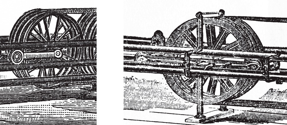
Figure 3: (l-r) 1884 and 1893 traveling sheave carriages 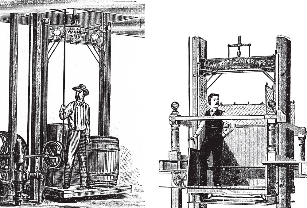
Figure 4: (l-r) 1884 freight platform and 1893 freight car 
Figure 5: Charles H.M. Atkins, “Hydraulic Elevator,” U.S. Patent No. 508,159 (November 7, 1893) 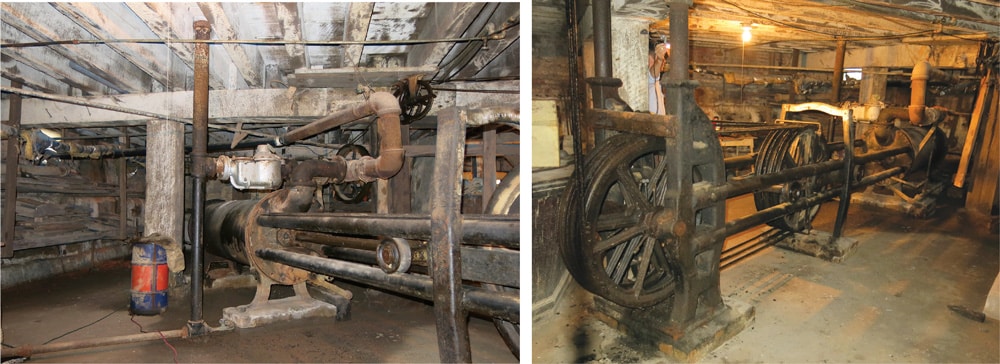
(l-r) Figures 6 and 7: Golden Rule elevator 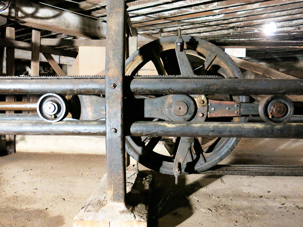
Figure 8: Golden Rule elevator: traveling sheave carriage 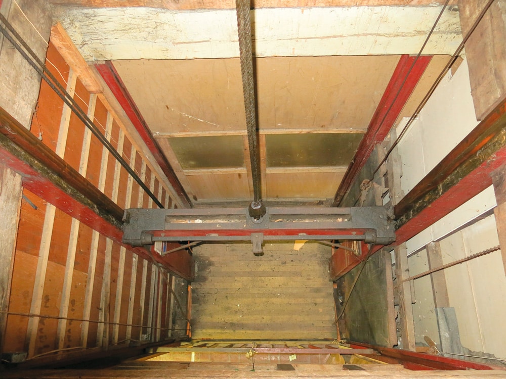
Figure 9: Golden Rule elevator: open platform car 
Figure 10: Clarence L. Colby, “Gravity Fire-Door Mechanism,” U.S. Patent No. 833,442 (October 16, 1906) 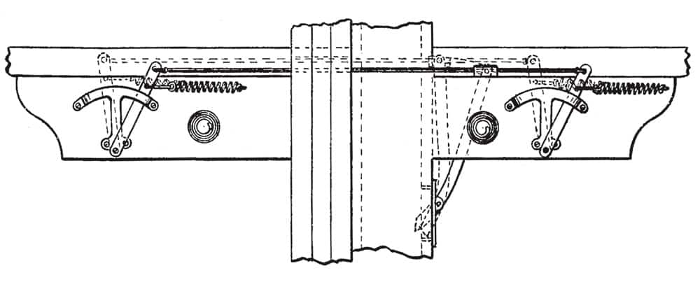
Figure 11: “Gravity Fire-Door Mechanism,” detail of door closing mechanism 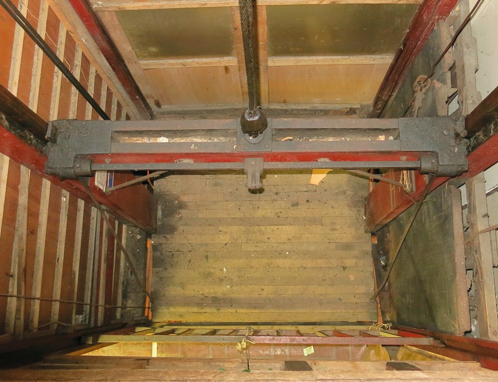
Figure 12: Golden Rule elevator: gravity fire door (at right side of shaft) 
Figure 13: Golden Rule elevator: gravity fire door, detail of door-closing mechanism (Compare to Figure 11.) 
Figure 14: Golden Rule elevator: gravity fire door, detail of door-closing mechanism (Compare to Figure 11; note the spring behind the vertical door panel.)
References
[1] Atay, S. (2013). Experimental Stress Analysis Of Complete Rail Fastening Systems, MSc Thesis, ITU Graduate School of Science Engineering and Technology, Istanbul.
[2] BS EN ISO 898-1:1999, Mechanical properties of fasteners made of carbon steel and alloy steel — Part 1: Bolts, screws and studs
[3] Imrak, C. E., Gerdemeli, I. (2000). Asansörler ve Yürüyen Merdivenler, Birsen Yayınevi, Istanbul.
[4] Merz, M., (2010). Practical Stress Behaviour of Complete Rail Fastening Systems, ELEVATION Vol.68, p56-62.
[5] Merz, M., (2008). Practical Stress Detection on Rail Anchors, Hilti Corporation, ELEVCON 2008, The 17th Int. Congress on Vertical Transportation Technologies, Thessaloniki, p268-277.
Get more of Elevator World. Sign up for our free e-newsletter.


