A Brief History of Elevator Wire Ropes, Part One
May 1, 2016
Wire elevator ropes in the 19th century and their maturation in the early 20th century are examined.
The humble hoisting rope occupies a unique place in the history of vertical transportation. A simple hemp rope lies at the center of one of the best-known elevator stories — Elisha Graves Otis’ demonstration of his Improved Safety Device at the 1854 Crystal Palace in New York City. A sophisticated carbon nanotube “rope” is the primary innovation driving the conceptual (and possibly literal) development of the proposed space elevator. It is, however, the wire rope that retains pride-of-place in elevator history as the longest-serving suspension means. It was the subject of numerous 19th-century articles that questioned its safety, and it has been featured in countless contemporary books, movies and TV programs that predicate disaster on its failure. This History series will address the introduction of wire elevator ropes in the 19th century and their maturation in the first half of the 20th century.
The invention of wire rope more-or-less paralleled the invention of the passenger elevator, and, by the 1870s, wire rope had become the rope of choice for elevator use. Due to their relative newness, both the elevator and wire rope faced similar challenges with regard to safety concerns. The older hemp hoisting rope had a long history of use, and its strengths and weaknesses were well known. However, a rope made of wire was an entirely different matter. This difference was effectively summarized in the June 22, 1878, issue of American Architect and Building News, which included a brief article on elevator ropes. The article expressed the primary concern in its opening sentence:
“The sudden introduction in our large cities of elevators, most of which are hung by wire ropes, has led people to wonder what will happen when they have had a year’s wear, and why there should not, after a while, be a breaking of ropes, and consequent accidents all over the country.”
The key concern centered on the endurance of wire rope and its reaction to constant and repeated bending as it passed around winding drums and over sheaves. One of the aforementioned article’s key assumptions was that “everybody knows, at least, that reiterated bending weakens wire, whether it be by granulation or by the constant extension of its fibers.” The challenge was, in spite of “knowing” that this action occurred, there was no easy way to judge when a rope was no longer safe for use. The article claimed that the John A. Roebling’s Sons Co. had recently provided good advice regarding the use of wire rope. They had stated that “large drums, sheaves and pulleys are absolutely necessary for the long life of a wire rope.” They also suggested that “ropes on passenger elevators ought to be changed every two years.” Interestingly, John A. Roebling’s Sons claimed that “the best elevator builders,” while they understood the need for large drums and sheaves, were often restricted in their use due to the space limitations of penthouses and mechanical rooms. This raises intriguing questions about the conversations among architects, engineers and elevator builders over the integration of this new technology into new and existing buildings.
Questions about the safety and proper use of wire rope were continually raised throughout the 1880s and 1890s and were, in part, finally answered by the development of a “standard” elevator wire rope. Hazard Manufacturing Co. of Wilkes Barre, Pennsylvania, specialized in the manufacture of wire rope and was one of a half-dozen American companies that made this new product. The September 15, 1896, issue of the Street Railway Review described the contents of the company’s new catalog, which gave “special attention to. . . the manufacture of standard elevator ropes.” The standard elevator rope was “composed of six strands, 19 wires in each strand, or 114 wires in the rope, the several strands laid firmly about a hemp center, which forms a cushion and gives elasticity to the rope.” The rationale behind its design was described as follows:
“Of the 19 wires in each strand, 12 are outer or wearing wires and contain 60% of the total strength of the rope; seven are inner or pulling wires, are never subjected to wear and contain 40% of the total strength of the rope. The center wires form a reserve strength after the outer wires are worn or broken.”
The development of the standard elevator rope was accompanied by the development of standard-use practices, which were summarized in a 1902 publication on elevators produced by the International Correspondence Schools (ICS). This material was addressed under the heading “Care of Wire Ropes, Cables and Guides,” and it provides additional insights into the use of elevator ropes. The presence of the hemp center rope made wire ropes “more pliable and thus more durable, on account of the short bends over comparatively small pulleys, or sheaves.” The use of wire ropes also required a means to ensure their “preservation” in elevator shafts, a need that was met by proper lubrication:
“To prevent rusting, raw linseed oil should be used and applied with a piece of sheepskin. John A. Roebling’s Sons recommend[s] to mix the linseed oil with the equal parts of Spanish brown or lampblack. The Otis Elevator Co. recommend[s] a mixture of seven parts of linseed oil and three parts of tar oil. Another good preserving lubricant is made by heating and mixing well cylinder oil, graphite, tallow and vegetable tar. When the ropes, or cables as they are called frequently in elevator work, have once become well soaked, they need oiling only about every third or fourth month.”
However, it was also noted that ropes “should not be allowed to become dirty and gummy.” Given the nature of the suggested lubricants, this must have been a challenging prospect.
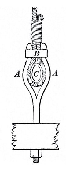
The ICS author also addressed rope replacement, noting that “particular attention must be given to the fastenings.” The chief recommendation was to “carefully reproduce the joint as it was originally made” by the elevator manufacturer. A typical shackle used by Otis Elevator was described as follows (Figure 1):
“It consists of a split rod, the two legs A, A of which are bulged out and provided with noses at the ends. A collar B straddles the legs and eventually abuts against the noses. The rope is brought through the collar, bent over a thimble C, and passed back again through the collar, after which the free end is fastened by wrapping with wire. The wrapped end of the rope should be at least 8 in. long. The inside surfaces of the legs A and the outside surface of the thimble are concave to conform with the rope.”
When attaching the rope to the winding drum, it was recommended that, when the car was at its lowest position, the rope should “encircle the drum several times to reduce the stress at the point of fastening.”
By 1900, the use of wire rope was an accepted feature of the industrial landscape, and the use of standard elevator wire rope was an equally accepted aspect of elevator operation. American Steel & Wire Co.’s 1913 catalog illustrated the widespread use of wire rope and contained a wealth of information, which was presented in a textbook format that featured 10 chapters, four appendices, a glossary and an index. Two chapters were devoted to the prices of the company’s various products, while eight chapters focused on the science and use of wire rope:
- Chapter 1: Standard Methods and Facilities for Testing Wire Rope
- Chapter 2: Materials Composing Wire Rope and Their Properties
- Chapter 3: Standard Types of Wire Rope Construction
- Chapter 4: Variety of Uses of Wire Rope
- Chapter 5: Mechanical Theory of Wire Rope
- Chapter 6: Practical Hints and Suggestions
- Chapter 7: Instructions on Ordering Wire Rope
- Chapter 8: Typical Applications of Wire Rope in Practice
The sections that addressed elevator ropes served as a reminder that different elevator systems required different types of rope:
“When ordering rope for elevators, state whether hoisting, counterweight, or hand or valve or safety rope is wanted, also whether right or left lay is desired. The ropes used for these purposes are different and are not interchangeable.”
The diversity of elevator ropes was reflected in the design of American Steel & Wire’s standard hoisting rope, which was produced in six grades or strengths: Iron, Mild Steel, Crucible Cast Steel, Extra Strong Crucible Cast Steel, Plow Steel and Monitor Plow Steel. The company’s standard iron rope was primarily designed for use on drum machines and was “used for elevator hoisting where the strength is sufficient” (Figure 2). It was also described as “almost universally employed for counterweight ropes, except on traction elevators.” Its Mild Steel Elevator Hoisting Rope was designed “especially for traction elevators in tall buildings where, on account of [the] usual quick starting and stopping, a stronger and lighter rope is required.” Shipper or control ropes (also called tiller or hand ropes) differed from standard ropes in that they were composed of six strands of 42 wires each, which were wrapped around seven hemp cores (Figure 3).
In addition to providing detailed information on a wide variety of wire-rope types, the catalog also included schematic drawings that illustrated their proper application. These included 17 elevator-related drawings that depicted direct-, side- and horizontal-plunger hydraulic elevators; geared and traction electric elevators; and electric and belt-driven worm-geared elevators. The drawings’ emphasis on the application of wire ropes makes them a unique resource. Two versions of direct-plunger elevators were depicted — one with a shipper rope and one with an in-car controller — and the presence of two elevation drawings for each system permits a thorough understanding of these elevators (Figure 4). The same level of detail was provided for side-plunger hydraulic elevators (manufactured by Otis) and horizontal-plunger hydraulic systems (Figures 5 and 6). The electric elevator drawings are of particular interest, because, in 1913, they represented the newest systems on the market. The electric drum machine featured an interesting array of sheaves for the car and counterweight ropes, while the worm-gear machine employed a winding drum located near the midpoint of the shaft (Figures 7 and 8). The traction elevator drawing effectively illustrated its inherent simplicity and the potential of this new design (Figure 9).
The variety of elevator types illustrated in American Steel & Wire’s catalog represented the diversity of elevator systems prevalent in the early 20th century, as well as the importance of wire rope to their operation. Part Two of this article will follow this story through the 1930s, which encompasses the continued development of the traction elevator and the writing of the first elevator safety codes.

Figure 1: “Otis Elevator Co. Shackle,” ICS Reference Library (1902) 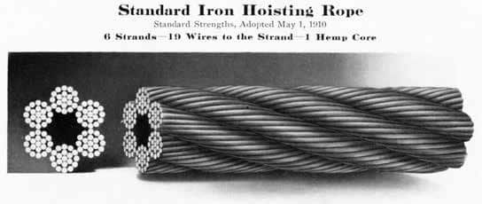
Figure 2: “Standard Iron Hoisting Rope,” American Wire Rope: Catalog & Handbook, American Steel & Wire (1913) 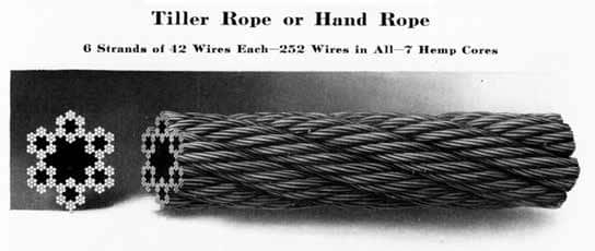
Figure 3: “Shipper Rope,” American Wire Rope: Catalog & Handbook, American Steel & Wire (1913) 
Figure 4: “Direct Plunger Hydraulic Elevators,” American Wire Rope: Catalog & Handbook, American Steel & Wire (1913) 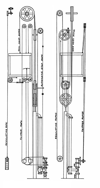
Figure 5: “Side Plunger Hydraulic Elevator,” American Wire Rope: Catalog & Handbook, American Steel & Wire (1913) 
Figure 6: “Horizontal Hydraulic Elevator,” American Wire Rope: Catalog & Handbook, American Steel & Wire (1913) 
Figure 7: “Electric Drum Machine,” American Wire Rope: Catalog & Handbook, American Steel & Wire (1913) 
Figure 8: “Worm Gear Electric Elevator,” American Wire Rope: Catalog & Handbook, American Steel & Wire (1913) 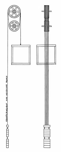
Figure 9: “Traction Elevator,” American Wire Rope: Catalog & Handbook, American Steel & Wire (1913)
Get more of Elevator World. Sign up for our free e-newsletter.


