A Houser Horizontal Hydraulic Elevator Engine, Part One
Sep 1, 2013

The subject of this article was brought to the attention of ELEVATOR WORLD by Gary Ritch of Syracuse, New York. Ritch is owner and operator of the Central Variety Store, located in the heart of the city. A few years ago, he moved his business to its current location, an existing five-story building on South Salina Street, which, as far as the realtor knew, had no elevator. As is common when moving into a new building, Ritch pursued a number of renovation projects. One of these involved demolishing a basement wall, behind which he found an elevator engine that had been built in the early 1890s by Houser Elevator Co. of Syracuse (Figure 1). Subsequent demolition revealed the elevator car and its walled-in shaft that extended from the basement to a rooftop penthouse. After removing a pile of debris that surrounded the engine, Ritch cleaned it and built a low wall that separated it from the adjacent space, essentially placing the engine on display. This April, I had the pleasure of seeing this remarkable engine and am delighted to have the opportunity to now present it to EW readers.
My pleasure in writing this month’s article derived in part from having the opportunity to explore an elevator engine type I had previously only seen in photographs and from trying to solve the puzzle the engine presented in terms of its actual operation. On one hand, the engine is a classic example of a horizontal hydraulic engine. These engines employed a horizontal cylinder, a piston rod (or rods) and a series of multiplying sheaves. A push-type engine featured fixed sheaves at the rear of the cylinder (adjacent to the shaft), while the pistons were attached to a set of traveling sheaves in front of the cylinder. The hoisting cables were attached to the cylinder and wrapped around the two sets of sheaves, and the car moved up and down the shaft as the piston pushed the sheaves apart or pulled them together. The “multiplying action” of the sheaves meant the piston was only required to move a relatively short distance to raise or lower the car several feet. Figure 2 depicts a similar engine type built in the 1880s by L.S. Graves & Son of Rochester, New York.
However, while it is possible to find numerous drawings and photographs of 19th-century push-type engines, very few published images illustrate the piping associated with these machines. Those that depict a full installation do not resemble this system. The one exception found thus far is an image published in the early 1880s by Crane Brothers Manufacturing Co. of Chicago, which depicts a similar configuration of vertical and U-shaped supply and discharge pipes (Figure 3). Unfortunately, the text that accompanied this image did not explain the piping plan.
It is, however, possible to offer an explanation of the Houser Elevator piping system based on information gleaned from sources such as John Jallings’ Elevators: A Practical Treatise on the Development and Design of Hand, Belt, Steam, Hydraulic and Electric Elevators. The water supply and discharge lines are 5-in.-diameter steel pipes. The primary shutoff valve (manufactured by Crane Brothers) is visible in the far right lower corner of Figure 1. The two vertical pipes – one located immediately adjacent to the shutoff valve and the other adjacent to the engine control valve – were used to reduce the impact of air on the engine. It was not unusual for city water supplies to include a substantial amount of air. The vertical pipes, which were equipped with air cocks, were used to capture and release this air.
The U-shaped pipe configuration was known as a “siphon relief” and was a safety feature often added to horizontal hydraulic elevators (Figure 4). If the car were to be stopped by an obstruction that extended into the shaft, the valves would remain in an open position, and it would be possible for the water in the cylinder to slowly drain. Therefore, when the obstruction was removed, the car could fall to the bottom of the shaft. The siphon relief prevented this from happening, in that it literally functioned as a “siphon,” which was:
“. . . set in the discharge pipe between the valve and the sewer. . . . The upper end or bend of which was above the top side of the cylinder. In this upper bend a small check valve opening inward was inserted, and when any obstruction of the car relieved the water in the cylinder of the pressure which was forcing it out, the admission of air through the check valve, which at once occurred, would allow the water in that leg of the siphon to drain away, while the water remaining in the other leg would balance what was left and prevent any further outflow.”
Thus, although several questions remain – such as why two vertical air-release pipes were needed – the basic piping system appears to conform to a normative method of supplying and discharging water to and from this type of engine.
The engine control valve is another matter: it bears no resemblance to any published images of horizontal hydraulic engine control valves (Figure 5). It does, however, closely resemble a type of control valve used on vertical hydraulic engines, particularly those manufactured by Otis (Figure 6). The control valve is curious in that the type used, which employs a pilot valve to control the main valve, was more commonly used on high-speed hydraulic systems found in much taller buildings. The small sheave located behind the pilot valve (which controlled its motion) was operated from the car via a lever that moved a shipper rope. The type of main valve employed was known as a “differential valve,” because the upper piston has a larger area than the lower piston. This resulted in constant pressure against the bottom of the upper piston, which depended on the difference between the areas of the upper and lower pistons.
However, the comparison of the Otis and Houser valves seen in Figure 5 also reveals some differences, such as the diagonal pipe that connects the pilot valve to the bottom of the differential valve. This feature, known as a bypass pipe, is probably present due to the use of a “throttle” between the upper and lower pistons. The throttle was designed to accomplish three goals:
“(1) It serves, if carefully adjusted, to deaden the noise occasioned by the circulating water. (2) It serves as a brake while descending, in case of an extra load on the car, preventing it from attaining undue speed. . . . (3) If any pipe or connection between the supply and valve should break, the water cannot back up from the circulating pipe out through the supply port faster than it can leak around the outside of the throttle.”
Figure 7 illustrates a typical throttle valve designed for an Otis vertical hydraulic machine. (Note the dotted diagonal pipe shown in the drawing’s center.) This drawing also references another feature found in the Houser engine – a “stop valve” (Figure 8). This safety device is visible to the left of the control valve, and its presence is indicated by the large spur gear with the attached weight hanging down. The spur gear was rotated by a pinion gear, which was connected to a small sheave attached by a rope to the front of the traveling-sheave armature. If the traveling sheaves were pushed too far along the rails, the pinion gear would be engaged and rotate the spur gear, which would, in turn, shut off the flow of water into the cylinder and stop the elevator. When the traveling sheaves began to move back toward the cylinder, the pinion gear would rotate in the opposite direction, and the weight would swing down and return the valve to an open position. (The current gravel bed under the engine prevents the stop valve from swinging down.)
A final feature, located beneath the stop valve, is a small relief valve. The placement of this valve (between the horizontal cylinder and the control valve) was intended to alleviate the possibility of “water hammer” (also known as “water ram”) occurring if the control valve was closed too rapidly when the car was ascending and the piston was moving into the cylinder.
This broad overview of the operation of this engine is, of course, based on some informed guesses and is partially predicated on the assumption that, because something looks like something else, it must be the same thing (i.e., the Houser control valve and its resemblance to the Otis valves). Adding to the difficulty of this assessment process is evidence that pipes were changed over time, and that the system may have been modified during its years of operation. (For example, the copper pipe that supplied water to the pilot valve is probably not the original supply pipe.)
A careful inspection of the elevator also raises other questions. The elevator lacks overt “branding” in that a full company name does not appear anywhere on the engine or its components. Although selected control-valve pieces and the traveling sheaves feature the initials “E.W.H.” (for “Edgar W. Houser”), the actual company name is conspicuously absent. Many (but not all) of the engine’s components have part numbers cast or stamped onto them. (For example, the control-valve components are all identified by three-digit numbers beginning with “7,” which would seem to indicate an orderly system of production predicated on the manufacture of multiple pieces at a time.) Finally, the elevator also employs components made by other manufacturers, including Crosby Steam Gage & Valve Co. of Boston (relief valve and other brass pipe fittings), Jarecki Manufacturing Co. of Erie, Pennsylvania (5-in. water pipes) and Carnegie Steel Co. (traveling-sheave rails).
Other questions concern the company founder (Edgar W. Houser) and the business’ history and importance in the local and regional elevator markets. Part Two of this article will trace the history of Houser Elevator from its origins in the 1880s to the death of its founder in the 1920s. A key part of this story will be placing the construction of the hydraulic elevator examined above into this story. I would like to extend my sincere thanks to Ritch for his willingness to share this extraordinary machine with me and with EW. I would also ask EW readers to contact us and let us know if there are similar machines still in operation (or in hiding) that deserve our attention. I am ready to plan my next “road trip” to explore and document interesting old elevators.

Figure 1: 1890s horizontal hydraulic elevator engine, Houser Elevator Co. (photo courtesy of Gary Ritch) 
Figure 2: 1880s push-type horizontal hydraulic elevator engine, L.S. Graves & Son, Rochester, New York 
Figure 4: Siphon relief, John Jallings’ Elevators: A Practical Treatise on the Development and Design of Hand, Belt, Steam, Hydraulic and Electric Elevators, p. 100 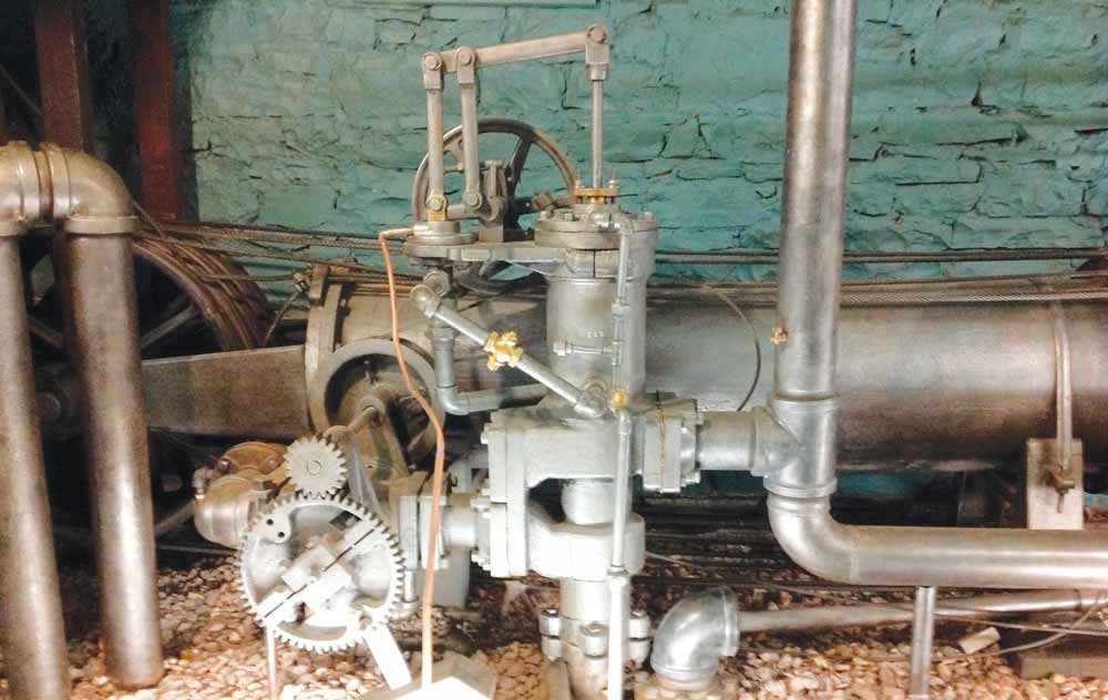
Figure 5: 1890s horizontal hydraulic elevator engine, Houser Elevator, detail of con-trol valve and siphon relief Continued 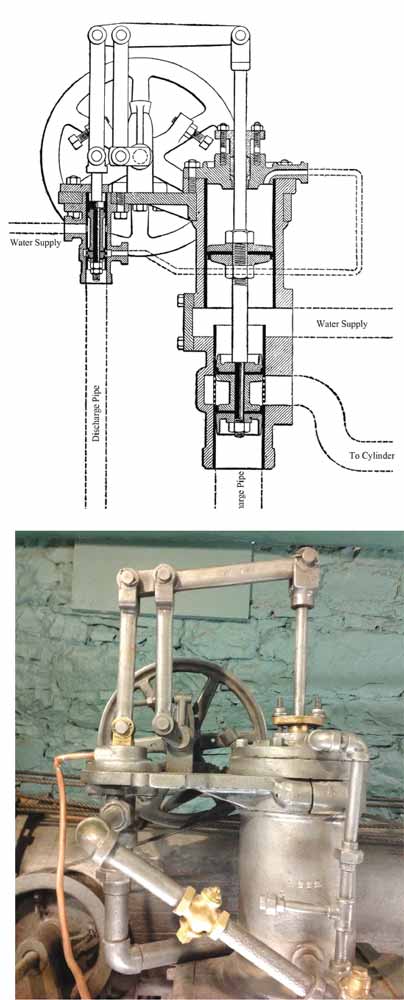
Figure 6: (l-r) Drawings of an Otis control valve and a Houser Elevator control valve 
Figure 7: Drawing of an Otis control valve 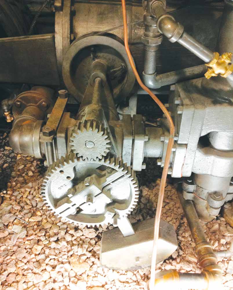
Figure 8: A Houser Elevator stop valve
Get more of Elevator World. Sign up for our free e-newsletter.

