A New Compact Mrl Hydraulic Lift For Mid-Rise Buildings
Apr 1, 2019
This Product Spotlight on the HILA system presents new cylinder technology to overcome old limitations.
This paper was presented at ![]() Berlin 2018, the International Congress on Vertical Transportation Technologies, and first published in IAEE book Elevator Technology 22, edited by A. Lustig. It is a reprint with permission from the International Association of Elevator Engineers
Berlin 2018, the International Congress on Vertical Transportation Technologies, and first published in IAEE book Elevator Technology 22, edited by A. Lustig. It is a reprint with permission from the International Association of Elevator Engineers ![]() (www.elevcon.com).
(www.elevcon.com).
In general, hydraulic lifts have been limited to low speeds and, because of cylinder buckling, suitable only for low-rise buildings. A new kind of cylinder technology, the Hydraulic Infinite Linear Actuator (HILA), has the potential to eliminate these limitations. Because this new actuator technology allows for very long strokes and high speeds, hydraulic lifts are now an option for mid-rise buildings. Compared to current hydraulic lift systems, the HILA cylinder is compact and uses resources efficiently, and allows up to five times greater hydraulic pressure.
Development of new products must be based on life cycle assessments (LCAs). HILA technology is better compared to conventional electric and hydraulic lifts, and to electric linear motor drives, when the whole life cycle is considered. This takes into account the environmental impact from both material usage and energy consumption during the usage period.
Introduction
In the past, hydraulic lifts were the main solution for low-rise applications, but the past 20 years have seen hydraulic lifts almost disappear from the new-installation market, replaced by traction lifts with counterweights. This has come with a cost, however: in applications with limited usage, such as in residential buildings, the environmental impact from the manufacturing of the lift is greater than the impact during the usage phase. Thus, a system without a counterweight would be preferred in such applications.
The megatrend of urbanization brings increased demand for mid-rise residential buildings. Our study shows that most of these buildings would have less impact on the environment if the lifts were built without a counterweight. According to the Global Lift and Escalator Sales Market Report 2016, there were 1.2 million lifts sold worldwide during 2016.[7] Based on our LCA considering the environmental impact, more than 600,000 of these would be best suited for HILA technology.
The Nature of the Hydraulic Lift Problem
In industrial and mobile systems, when it comes to transmitting power, hydraulics usually have several advantages over other power sources. With hydraulics, high forces can be controlled with great accuracy and few moving parts, and the power density is very high. There are, however, a number of problems that occur in conventional hydraulic cylinders when the application requires long linear motion, and this explains why hydraulic lifts are not used for mid- and high-rise buildings. The problems are buckling, low hydraulic stiffness, low hydraulic-system pressure and assembly. Buckling is probably the main problem limiting the stroke length of conventional hydraulic cylinders. In lift machinery, this can be solved using a pulling cylinder in combination with ropes and associated equipment.
Hydraulic stiffness adversely affects the dynamic behavior and controllability of the overall lift system. By significantly decreasing the system pressure, the influence of stroke length and, thus, hydraulic stiffness and natural frequency, can be mitigated. It has resulted in very low system pressures in today’s hydraulic lifts, about 4 MPa (approximately 580 psi). But, decreasing the system pressure requires much larger components and oil volumes. A dedicated machine room is usually needed, because of the space- consuming hydraulic supply system. A hydraulic lift system operating in a five-story building might require a large amount of oil. Should an external cylinder or hydraulic reservoir begin to leak, it may create environmental issues, such as contaminated groundwater.
Long-stroke conventional hydraulic linear cylinders obviously have difficult technical, economic and environmental problems. The advantages normally associated with hydraulics in other applications — compactness and high power density — diminish with increased stroke length. Given the desirability of the above- mentioned advantages, the question arises: is there an alternative to conventional hydraulic cylinders where high system pressure and compactness can be maintained, even at long strokes?
HILA solves these problems and may allow for a hydraulic lift alternative for mid-rise buildings. With HILA, up to five times higher system pressure, or 20 MPa (2,900 psi), can be used, compared to conventional hydraulic cylinders in long-stroke applications. Higher pressure levels are also possible for mobile applications. The actuator has a higher stiffness compared to conventional hydraulic cylinders, and the increased design pressure reduces the natural frequency of the system.
The cylinder has a high stiffness, thanks to its small volumes. This is advantageous, as it affects the static accuracy that can be achieved when positioning loads, and it determines the nature of the dynamic response of systems. When using long stroke lengths in hydraulic cylinders, it is usually difficult to use high hydraulic pressure, because it reduces the natural frequency in the system. It can be shown that the natural resonance frequency ωh for a lift cylinder is:

where 𝐿 stroke is the stroke of the cylinder and P system is the system pressure. A much higher natural frequency can be achieved at high system pressure levels because the HILA cylinder has a much shorter stroke compared to that of a conventional lift cylinder. The higher system pressure and small chamber volumes allow for an even more compact system design, with lower flow levels, less energy loss in valves and a significantly smaller reservoir volume.
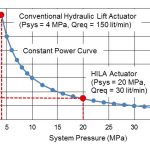
In Figure 1, a constant power curve has been drawn to show the relationship between system pressure and the required maximum flow. The figure illustrates the drastic pressure increase that HILA technology allows and its advantageous consequences. In a 10-kW hydraulic lift system that normally operates at a maximum system pressure of 4 MPa, a maximum flow of 150 lpm is required. With HILA technology, the system pressure can be increased to 20 MPa, thus lowering the maximum flow rate to 30 lpm.
When the system pressure can increase five times, and the maximum flow can be reduced to one-fifth, it allows for a much smaller, easier and more cost-effective supply system. The reservoir can be 90-95% smaller. The entire supply system,
including the electric machine, can be placed in confined spaces, and no dedicated room is needed for the hydraulic supply. Unlike conventional hydraulic lifts, HILA technology is independent of the number of floors in terms of material usage. The HILA system requires the same amount of material, except for the piston rod, regardless of the number of floors.
HILA Technology
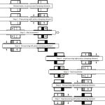
HILA technology combines two short-stroke cylinders with two engaging and disengaging clamping mechanisms into one actuator with long stroke length. The clamping mechanism, a hydraulic membrane, connects the piston and rod when pressurized. By using simple logic valves for pressurizing, the piston and rod can be quickly connected and disconnected with maximum secure and reliable clamping. The motion of each single short-stroke piston linked together by the clamping mechanisms creates the motion of the piston rod. For movements, one of the pistons is connected alternatively to the rod, providing the drive. In this way, the two pistons are moving the rod alternatingly in a kind of rope-climbing motion. The HILA innovation is presented in more detail in “Novel Linear Hydraulic Actuator” by M. Landberg, M. Hochwallner and P. Krus.[1] Figure 2 describes the actuation process of the cylinders; aft er step 7, the process continues with step 2. (For a video animation of HILA in action, visit youtube.com/watch?v=tVJkqC2w5ws.)
The core of the invention has been used for many years in various high-precision hydraulic chuck holders. This hydraulic hub/shaft connection has a compact design, is quick-locking and has accurate positioning. The locking is done with the help of an external hydraulic pressure source separate from the clamping mechanism.
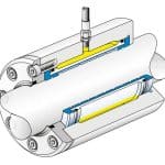
The clamping mechanism is an open sleeve of a bronze material with seals, which is built into the piston in the cylinder. It transmits only axial forces and is suitable when repositioning needs to be done frequently, fast and precisely.[1]
Conventional seal solutions between the piston rod and cylinder prevent external leakage to some extent, but create fairly high friction and generate energy loss. To design a power-efficient system that delivers better performance, it is essential to minimize friction and energy loss. This can be accomplished by replacing the wear ring and rod seal between piston and cylinder with bronze bearings, an arrangement that brings several advantages. With the use of a flexible boot, a higher leakage of cylinder seals is allowed. This reduces friction and energy losses, and the power efficiency of the cylinder is increased. Furthermore, higher rod speeds are permitted when the friction is reduced. This permits, for example, high-speed lifts in mid-rise buildings.[1]
Because the piston has a relatively short stroke, it is possible to cover the cylinder with boots over the piston and capture leaked oil, which is then returned to the reservoir. The boot solution significantly decreases the risks of oil contamination, while offering greater power efficiency and rod speed. It should be noted, though, that control accuracy can become too low if the leakage becomes too high.[1]
Simulation and Optimization Study
The control issue for HILA technology is to mimic the motion behavior of a conventional cylinder. The goal is to maintain a constant actuator velocity, even during the load shift from one cylinder to the other, in a smooth and pulsation-free way. The load case raising a lift car vertically from floor A to floor B can be characterized as a combination of inertial load and force load. Hochwallner and Krus, in “Motion Control Concepts for the Hydraulic Infinite Linear Actuator,” present simulation results based on a load case similar to a lift, lifting a mass.[3] A control concept with active load shifting is proposed and analyzed, and the result is a smooth actuation motion with only marginal jerk. The HILA actuator consists of two cylinders driven by fast servo valves. The control loop is closed with accurate position sensors.
In a lift application, expensive servo valves and sensors are not an option. The challenge here is to implement a cost-effective control system that can provide a smooth motion and constant lift speed without unacceptable jerk at load shift, using ordinary direction valves and simple position sensors.
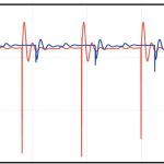
A HILA system with simple, cost-effective directional valves and position sensors was studied and analyzed at Linköping University (LiU). The lift application in this study has been implemented as a HOPSAN simulation model. HOPSAN is a user-friendly, multidomain system simulation tool for hydraulics and mechatronics developed at the division of Fluid and Mechatronic Systems (FLUMES) at LiU.[9] A system characterized by low pulsation levels and a comfortable motion was designed (Figure 4).
The result of simulations with optimized components shows that it is possible to achieve the same functionality and performance with simple, slightly modified directional valves and simple discrete position sensors, as that realized with an advanced hydraulic servo system. The simulation study shows HILA technology can be a cost-effective and competitive alternative for lifts in mid-rise buildings.
LCA Study
Introduction
The increased awareness of the importance of environmental protection and the possible impacts associated with products, both manufactured and consumed, has driven interest in the development of methods to better understand and address these impacts. One of the techniques being developed for this purpose is LCA.
LCA addresses the environmental aspects and potential environmental impacts throughout a product’s lifecycle, from raw materials acquisition through production, usage, end-of-life treatment, recycling and final disposal. In 1997, the European Committee for Standardization published its first set of international guidelines for LCA performance. This standard series, ISO 14040, has become widely accepted among the practitioners of LCA and is continuously being developed along with progressions within the field of LCA. There are four phases in an LCA study: the goal and scope definition phase, the inventory analysis phase, the impact assessment phase and the interpretation phase.
Since the evaluation of HILA technology for lifts is in the study phase, we decided not to perform a complete LCA at this stage, but rather base it on the previous Miljögiraff LCA Report 56.[6] The complete LCA report is consistent with the ISO 14040 series and Environmental Product Declaration Product Category Rules draft for lifts. The terminology defined in ISO 25745-2 for lifts is used consistently throughout the study. In this study, a hydraulic lift is compared to a traction lift with counterweight. Two aspects have, by far, the most impact on the environment: the manufacturing of the product and the usage energy.
Input Data
The data derived from the Miljögiraff LCA Report 56 and used in this new study are the following:
- ReCiPe Endpoint per kilogram material is 0.9.
- ReCiPe Endpoint per kilowatt hour energy used is 0.085.
The definition of ReCiPe Endpoint can be found in Miljögiraff LCA Report 56.[6]
Systems Compared
In this study, we have compared four different possible solutions for lifts in residential buildings up to 20 stops. The lifts have 1000-kg-rated loads and rated speed of either 0.63 mps (four stops) or 1 mps (eight and 20 stops):
- Conventional hydraulic lift: four and eight stops
- HILA hydraulic linear lift: four, eight and 20 stops
- Traction machine-room-less with counterweight: four, eight and 20 stops
- Electric linear lift: four, eight and 20 stops
Estimation of Material
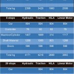
The material content for the four different systems can be seen in Table 1.
Estimated Energy Consumption
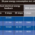
The energy consumption for the four different systems has been theoretically evaluated. The average load is calculated according to ISO 25745-2 for user Category 1 for four stops, and user Category 2 for eight and 20 stops. The real potential energy (mass X gravity X height) is calculated in one direction; in the other direction, the residual energy is fed back to the supply net. The efficiency rates that have been used for respective subsystems can be seen in Table 2. The total energy consumption for 20 years, including standby usage, can be seen in Table 3.
Result of the LCA
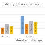
The result of the LCA shows that, for low-rise residential buildings, conventional hydraulics are still attractive. For mid-rise buildings, the HILA concept is the most attractive one, which is illustrated in Figure 6. The LCA is calculated with electrical energy feedback for HILA, traction and electric linear.
Discussion
The compact hydraulic system that will drive the lift with actuator and supply in the form of a pump and electric motor will be placed on a wall in the lift shaft. The actuator attachments on the lift shaft wall and attachments for wire wheels can be fitted with suitable dampers that mitigate the remaining high-frequency pulses.
HILA technology has been analyzed extensively in several academic works at FLUMES at LiU in Sweden.[1-3 & 5] The technology has been simulated and analyzed in HOPSAN models, and validated in the hydraulic rig at LiU. (See the video at youtube.com/watch?v=UCO-OQOdxtg.)
In this study, the focus has been on a mid-rise lift application based on simple directional valves. The next development step will be to build a lift prototype, based on HILA technology, at Hydroware to validate the result of simulations and optimizations in HOPSAN and Simulink simulation tools.
In the past several decades there has been a lot of focus on getting energy consumption down during usage of different products, but very little focus on the environmental impact from the material used for manufacturing. This study gives a clear indication that the material used to produce a lift with up to 20 stops in a residential building is crucial for the environmental impact during the lifetime of a lift.
Conclusions
In general, hydraulic lifts are limited to low speeds and are only suitable for low-rise buildings. The HILA actuator is a new kind of hydraulic cylinder technology that has the potential to eliminate these limitations. It allows for very long strokes and high speeds, which opens up the potential for hydraulic lifts in mid-rise buildings. The HILA cylinder is compact and efficient. It allows up to five times greater hydraulic pressure than today’s hydraulic lifts.
A HILA system with simple directional valves has been studied here. With the help of simulation and optimization, it is shown that pulsation-free motion can be obtained in a lift application based on these simple and cost-effective direction valves. The study shows that the patented HILA technology in this embodiment can be an interesting, competitive and cost-effective alternative for lifts in mid-rise buildings.
According to the Global Lift and Escalator Sales Market Report 2016,[7] there were 1.2 million lifts sold worldwide during 2016. Based on our LCA, HILA technology would be best suited for more than 600,000 of these, when the total environmental impact is considered.
Acknowledgement
This work was sponsored by the Swedish Governmental Agency for Innovation Systems (Vinnova). www.vinnova.se/en
- Figure 1: Different working points using a conventional hydraulic lift actuator and HILA actuator in a lift application
- Figure 2: The actuation process of the HILA cylinders
- Figure 3: The clamping mechanism built into a hub[8]
- Figure 4: Speed before (red) and after (blue) optimization
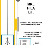
- Figure 5: The HILA Lift
- Figure 6: Result of LCA in ReCiPe Endpoints
- Table1: Material used to produce the lifts
- Table 2: Efficiency rates for respective sub system
- Table 3: Energy usage during 20 years in operation
References
[1] Landberg, M., Hochwallner, M. and Krus, P. “Novel Linear Hydraulic Actuator”. ASME/Bath 2015 Symposium on Fluid Power and Motion Control (FPMC2015).
[2] Hochwallner, M., Landberg, M. and Krus, P. “The Hydraulic Infinite Linear Actuator – Properties Relevant for Control”. The 10th International Fluid Power Conference (10. IFK), 2016.
[3] Hochwallner, M. and Krus, P. “Motion Control Concepts for The Hydraulic Infinite Linear Actuator”. 9th FPNI PHD Symposium on Fluid Power, 2016.
[4] Sachs, H., Misuriello, H. and Kwatra, S. “Advancing Lift Energy Efficiency”. Report A1501, January 2015, American Council for an Energy-Efficient Economy, 529 14th Street NW, Suite 600, Washington, DC 20045
[5] Landberg, M., Sethson, M. and Krus, P. “The Hydraulic Infinite Linear Actuator with Multiple Rods”, The 15th Scandinavian International Conference on Fluid Power, SICFP ’17, June 7-9, 2017, Linköping, Sweden.
[6] Miljögiraff Lca Report 56 Hydroware. Issued by Miljögiraff AB, 2015-03-30.
[7] Global Lift and Escalator Sales Market Report 2016. Reports – MnM Group.
[8] ETP-OCTOPUS, ETP Transmission AB (www.etptrans.se).
[9] Simulation tool HOPSAN (en.wikipedia.org/wiki/Hopsan).
Get more of Elevator World. Sign up for our free e-newsletter.
