A17/B44 Type B Safety Stopping, Part Two
Oct 1, 2018

Learn about safety performance in free-fall in the second half of this Engineering series.
Learning Objectives
- A basic understanding of the performance of Type B safeties in the free-fall mode, stopping the car by the safeties, on their own
- A basic understanding why the A17 committees were asked by the European code writers three decades ago to reexamine the need for safeties, designed and manufactured in the U.S., to be tested in the free-fall condition and certified by independent entities
- A basic understanding of the arguments for and against free-fall protection for Type B safeties three decades ago
- A basic understanding why the A17 committees concluded that free-fall protection of Type B safeties designed and manufactured in North America was no longer necessary, since the frequency of total suspension loss on a traction elevator was so low as to be almost negligible
- A basic understanding of the arguments for and against free-fall protection for Type B safeties as viewed in contemporary times
- A basic understanding why the A17 committees never codified free-fall type testing and certification of Type B safeties in the A17/B44 code
- A basic understanding of the operational steps of the mechanical systems, which cause time response delays in governor and safety application
- A basic understanding of the incremental speed increases during the governor and safety-activation process due to time response delays
- A basic understanding of the operational characteristics of a pit oil buffer in assisting in the retardation and stopping of a free-falling car, the safeties of which have slowed the car speed to that which can be safely withstood by the buffer
- A basic understanding of free-fall performance of Type B safeties in the free-fall mode, coupled with an oil buffer stop
In Part 1 of this series (ELEVATOR WORLD, April 2018), “A17 Interpretation 01-60,”[3] first published in 2002 and reconsidered by the ASME A17 Mechanical Design Committee and A17 Standards Committee in 2013, was examined. The technical points leading to the reaffirmation of A17 Interpretation 01-60 were presented in Part 1. The A17/B44 safety test method was compared to the non-A17/B44 test method, and the retardation and retarding force equations for the two cases, respectively, were presented. The emergency stopping of the elevator in an overspeed condition resulting from the simultaneous Type B safety stopping and e-stop braking was comprehensively discussed to explain the technical considerations of the A17 Mechanical Design Committee.
In Part 2 of this series, the free-fall safety stopping performance of Type B safeties will be examined from the perspective of A17 Interpretation 86-2,[1] issued more than three decades earlier in 1987. For the sake of continuity between Parts 1 and 2 of this series, the following format is used:
- Equation numbers (shown in parentheses) in Part 1 are continued sequentially in Part 2.
- Figure numbers from Part 1 are continued sequentially in Part 2.
- Table numbers from Part 1 are continued sequentially in Part 2.
- “Abbreviations, Acronyms and Terms” are presented in their entirety in the part in which they are used.
- Only those “Notations and Nomenclature” used in each part are presented in the part in which they are used.
- “References” are presented in the part in which they are used.
As noted in Part 1 of this series, the formulation and presentation of the relevant formulae and equations are necessary due to the complexity of the subject matter that deals with the elevator system motions., i.e., system dynamics. However, the commentary in both parts of this article is complete, and non engineers will not be disadvantaged by the inclusion of the mathematics.
Safety Stopping Performance in Free-fall
In the pre– and post- World War II eras, three U.S. states (namely, California, Pennsylvania and Wisconsin) and the U. S. General Services Administration, which is the procurement agency for the U. S. government, required certification tests of the free-fall stopping performance of Type B (FGC) Safeties. There was optional witnessing by the four agencies, depending upon budgetary constraints. The tests would be performed at the site of the manufacturer’s choosing, but the tests had to be witnessed by an independent third party, who would then certify the test results and issue a test report.
Since the Type B safeties deployed across the U. S. were free-fall tested to satisfy the four agencies, it was felt unnecessary to codify the free-fall test requirements in the A17 Code, since their free-fall performance verified their robustness in safely stopping the cars. Up through the mid 1970s, the National Bureau of Standards (NBS) was used by most major manufacturers to witness the tests and certify the results. Subsequently, Underwriters’ Laboratories (UL) has been used by some manufacturers to perform the third-party function. With the exception of Pennsylvania, this practice has been superseded by overspeed tests with the counterweight and suspension means functional. It was against this backdrop of free-fall safety stopping performance that the A17 Mechanical Safety Devices & Machine Design (MSD & MD) Committee formulated A17.1 code[4] Rule 900.2d2, i.e., with a high degree of confidence in contemporary Type B safeties designed and marketed by the major manufacturers in that era.
In the mid 1980s, the activities of ISO/TC 178 Working Group 4 (WG4) were underway, focused on the issue of free-fall safety stopping performance, which culminated in the development of A17 Interpretation 86-2. While this interpretation[1] verified the adequacy of Type B safeties designed to satisfy the overspeed test with the counterweight in the system as capable of providing free-fall protection, the A17 Standards Committee was asked by the EU members of the WG4 to consider codifying free-fall safety stopping in the A17.1 code as was done to satisfy the four agencies noted above. The interpretation request was assigned to the A17 Mechanical Design Committee to develop a proposed interpretation. Concurrently with the A17 Mechanical Design Committee’s study, the A17 Mechanical Product Certification Committee was formed to assess type testing of several products, e. g., oil buffers, interlocks, Type B safeties, etc., in the late 1980s. This latter committee concluded two points about Type B safeties:
- The frequency of total suspension loss on a traction elevator was so low as to be almost negligible. The anecdotal evidence did not support any conclusion that free-fall protection was necessary any longer in North America.
- Most safeties deployed in the North American market were, in fact, free-fall tested and certified to comply with the agencies noted above.
While the conclusions opposing type testing of safeties in free-fall was generally persuasive three decades ago, the second conclusion, albeit a minor one, is arguably no longer valid when considering that the major manufacturers no longer supply the majority of Type B safeties deployed in North America. The arguments favoring codified requirements for type testing safeties should be reexamined to take into account the changing commercial market and the possible benefits to type testing. The cross-continent sales of EU- and North American-designed safeties might provide incentive for type testing and certification, not to supplant field acceptance testing, but to supplement it. Notwithstanding, the probability of a total suspension failure in a reasonably well-maintained elevator system, coupled with the high suspension design factors of safety, is extremely low. A17/B44 Rule 8.6.1.1.1 requires that equipment covered within the scope of this code shall be maintained in accordance with Section 8.6.
A17 Interpretation 86-2
The need to have the A17 safety stopping requirements assessed in terms of the free-fall stopping capability started in 1986 at one of the semiannual meetings of the ISO Technical Committee 178 WG4 during which Andre Leenders, one of the noted European elevator engineers, claimed that a Type B (FGC) safety designed to meet the maximum A17 stopping distances, i.e., having a retardation, asaf = 0.35g, with rated load in the car, suspension ropes intact and counterweight attached, would be unable to retard and stop a free-falling, fully-loaded elevator if the suspension ropes failed for any reason. The author was the head of the U.S. delegation to ISO/TC 178 and one of the U.S. members of WG4.
In response to the author’s contention that Andre Leenders was reaching too large a conclusion based on an incomplete understanding of field safety-testing practices in the US, the author agreed that a formal interpretation from the A17 Main Committee would have heightened credibility in answering the issue of Type B (Progressive Safety Gear) safeties raised by Andre Leenders’ concerns. Since the technical issue affected all the elevator manufacturers in the U.S., NEII was requested to send the inquiry to the A17 committee as an industry issue, not confined to the interests of any single manufacturer. The inquiry to the A17 Main Committee asked:
“Is it the intent of Section 205 to require that all safeties be designed to safely stop an overspeeding car regardless of the cause of the overspeed, i.e., elevator system overspeed, or free-fall, etc.?”
As a result of extensive review by the A17 Mechanical Design Committee, the author prepared the proposed response to the inquiry. The MDC members were requested to review the proposed interpretation, together with all the mathematical analyses contained in it prior to a committee vote. Following their detailed review over three months, the MDC members unanimously agreed with the proposed A17 Interpretation 86-2, which stated:
“The A17.1 code does not specifically require that all safeties be designed to stop an overspeeding descending car or counterweight other than the condition where the suspension ropes are intact, i.e., not free-fall.
“In requiring conformance of Type B safeties to the stopping distances specified in Rule 205.3, it is the intent that a Type B safety will, in a free-fall condition, develop a retardation sufficient to reduce the free-fall speed, resulting in an elongated safety slide or a combination safety and buffer stop within the allowable speed range of the buffer.
“While the intent is the natural result of a mathematical analysis of the stopping distance equations, it is not notably evident in the specific rules.”
The ambiguity that arguably existed as to whether the A17.1 code addressed free-fall protection for Type B safeties was clarified by the issuance of A17 Interpretation 86-2.
In the development of A17 interpretation 86-2,[1] the following considerations were made:
- The A17 field safety test method requires the machine to be stopped during the test so that a combined braking and safety stop ensues. This combination safety and brake stop results in a lesser safety retarding force than would be required if the brake did not assist in the stopping. Notwithstanding the A17 test method, the prevalent test method followed by many enforcing authorities in the mid 1980s was to keep the machine running during the field-acceptance safety test, even though slack hoist ropes and counterweight ensued due to the tractive effort of the powered drive sheave. In performing this non-A17 field-test method, both the governor overspeed (GOS) and safety-operating switches (SOS) were jumped out, thus preventing any electrically assisted or mechanical braking to occur during the safety test. This non-A17 method resulted in the safety having a higher safety retarding force when the driving machine continues to drive during the field acceptance test than the A17 method would require. Both methods were presented in the interpretation, but the one resulting in the higher retarding force became the baseline for formulating the A17 interpretation. The selection of this larger safety retarding force based on the prevalent de-facto industry test condition benefitted the free-fall condition.
- A DWT gearless machine arrangement was analyzed. Accordingly, the rotational inertia effects of the rotating armature, drive sheave, driveshaft and brake drum of the machine were omitted. For the case where the driving machine is stopped due to the removal of electrical power when the SOS opens, which is the A17 test method, the rotational inertia of drive sheave/brake drum and armature are quantities of lower order of magnitude and are absorbed by the machine brake(s), and their exclusion from the analysis is justified.
- For the case where the gearless driving machine continues to drive during the safety stop, which was the non-A17 test method in prevalent use at the time, the rotational inertia of the drive sheave/brake drum and armature are quantities of lower order of magnitude, and their exclusion from the analysis is justified.
- A constant coefficient of kinetic friction between the faces of the FGC safety wedges and guide-rail faces, regardless of the rubbing speed, was assumed by the A17 committee. Most of the U.S. manufacturers used the constant coefficients of kinetic friction determined by John A. Dickinson when he performed the NBS tests, which included high speeds over 1,000 fpm.
- Where the safety only had sufficient retarding force to prevent the car from accelerating, it was assumed that the resulting elongated slide would not cause excessive wear of the safety wedges, which, in turn, would cause a reduction to the safety retarding force, thereby allowing the car speed to increase.
- In the unlikely event that the safety stopping retardation was unable to stop the free-falling car, a combination safety and buffer stop would ensue, thereby bringing the car to a combination safety and buffer stop within the speed range for which the buffer was designed. This was premised upon there being sufficient safety stopping retardation to decelerate the car from free-fall safety activation speed down to the speed for which the pit buffer was designed.
- The equations developed for A17 Interpretation 86-2 were derived using the D’Alembert Method and cross-checked by the Newton II Method and Hymans’ Equivalent System, and their equivalence to Equations 5 and 7, shown in the following sections. The equations given in Interpretation 86-2 are identified by the notation [86-2; (x)] in this article.
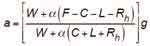
- The elevator-system retardation for the A17 Test Method (machine stopped) was given in Imperial dimensional units as:
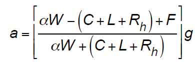
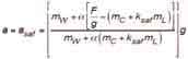
9. Equivalence to Equation 5 will be determined by converting the Imperial unit variables to SI units, which results in the following:

(Equation 31) The mass of the rated load is:
Since the mass of the hoist ropes is of small order as noted by Equation 3, it can be neglected. Substituting Equations 31 and 32 into Equation 30 yields:
It is seen that Equations 5 and 33 are identical.
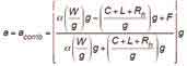
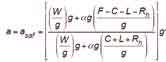
(10) The elevator-system retardation for the non-A17 Test Method (machine driving) was given in Imperial dimensional units as:
Equivalence to Equation 7 will be determined by converting the Imperial-unit variables to SI units, which results in the following:
Substituting Equation 31 into Equation 34 and noting that the mass of the hoist ropes is negligible, the following results:
It is seen that Equations 7 and 35 are identical. Therefore, the equations given in A17 Interpretation 86-2 are identical to the ones given in this article.
Based on the analysis and embodied considerations, official A17 Interpretation 86-2 was approved by the A17 Main Committee on March 11, 1987. In hindsight, the resulting Interpretation 86-2[1] was arguably one of technical convenience that took advantage of the prevalent test methodology favored by enforcing authorities, albeit a more stringent code-noncompliant test protocol.
Notwithstanding, reliance on the higher safety retarding force resulting from the prevalent non-A17 test method to defend the adequacy of the allowable A17 retardation range used for free-fall stopping capability certainly gives rise to the need for contemporary reassessment based on the prevalent A17/B44[6] test methodology now in standard use. The long-range study initiative on safeties would benefit accordingly.
While WG4 appreciated the official response of the A17 Main Committee, Andre Leenders still disagreed with the interpretation and countered with the following arguments at the October 12-13, 1987, meeting of the ISO/TC 178 WG4 held in Berlin and posited as follows:
- The U.S. manufacturers’ adherence to a non-A17 field test method, that did not comport with the published A17 field test method, was misleading and could result in other countries’ code committees reaching an erroneous conclusion about setting retarding forces due to unawareness of more stringent U.S. field practices.
- Andre Leenders agreed with the omission of the rotational inertia effects for gearless machine applications but opined that an analysis should be made in the case of low-speed AC geared machines with a heavy flywheel, with which the rotational inertia effects might be more pronounced. In this era, three decades after A17 Interpretation 86-2 was published, AC gearless machines are the predominant machine selection. Nevertheless, the rotational inertia effects are still lower by orders of magnitude, and their omission from the calculations remains valid.
- If a Type B (FGC) safety were designed and tested according to the A17 field test requirements, as published in A17, and produced a safety stopping distance at the long end of the slide, i.e., asaf = 0.35g, then that same safety would have insufficient retarding force to stop a free-falling car without assistance from the pit oil buffer.
- It might not be possible to develop a retardation due to the fast wear of the safety wedges at high speed and the resulting loss of retarding force as the wedges wear away, thereby causing a reduction to the effective safety spring forces.
- The coefficient of kinetic friction was erroneously assumed constant by the A17 committee, regardless of car speeds. Contemporary research conducted by Professor Klaus Feyrer, University of Stuttgart, including findings in the railroad industry, showed that the coefficient of kinetic friction decreased with increasing speed. Leenders opined that it would be wrong to ignore the technical research that validated the premise of decreasing coefficient as a function of increasing speed. The writer concurred and provided the WG4 with Otis test curves validating Feyrer’s and Leenders’ opinion.
Notwithstanding the extensive discussion and debate about the adequacy of the A17 safety stopping requirements that took place at the ISO/TC 178 WG4 meetings in 1986-1987, the European CEN committee (European counterpart to ASME A17) was not prepared to endorse Andre Leenders’ disagreement with the A17 committee on safety stopping. Andre Leenders’ technical opinions were accepted as those of an individual technical expert and did not reflect CEN code committee writers.
A17 Interpretation 86-2 Remains Valid
In January 2014, the A17 Mechanical Design Committee and A17 Ad Hoc Committee on Elevator Stopping reviewed A17 Interpretation 86-2 and concluded that the technical conclusions and supporting commentary contained in A17 Interpretation 86-2 remain valid:
- The A17 code, including the A17/B44 code,[6] regardless of edition after 1955, does not require free-fall protection inherent in the design of Type B safeties.
- The mathematical formulations of the required safety retarding force were presented for both operational cases of safety application, with and without mechanical braking assistance, as technical guidance for the user.
- The free-fall protection afforded by a combination safety and buffer stop, in the extreme, is not affected by the operational status of the driving machine brake and the opening of any electrical protective devices, since, in a free-fall condition, the suspension will have failed, and machine braking is not possible.
As part of the long-range study initiative, the conclusions about free-fall safety stopping capability in A17 Interpretation 86-2 should be examined further in connection with the potential high retardations resulting from a combination safety/buffer stop, the effect of sliding velocity on the coefficient of friction between the safety jaw/wedges that can result in “brake fade” and the prevalent field safety test method used uniformly now within the North American industry, more than three decades after Interpretation 86-2 was published.
The ASME procedures in effect through the 1990s permitted official A17 intent interpretations, which could include comprehensive commentary and mathematical analysis to explain the basis and rationale for A17 code requirements. Subsequent revisions to ASME procedures no longer permit the type of documentation contained in A17 Interpretation 86-2. The only opportunity now to provide published context to explain the thinking of the A17 Working Committees, such as the A17 Mechanical Design Committee and A17 Elevator Stopping Committee, is to have included supporting commentary as part of the rationale published during the A17 balloting process. The ASME procedures allow intent interpretations to use ballot rationale when explaining the basis for a code requirement. Alternatively, technical explanations can be included in the A17 Handbook,[7] published by ASME, or by other technical writings, such as this article. A17 Interpretation 86-2 was memorialized for a worldwide audience by EW in July 1988 in your author’s article “Stopping Capability of Safeties” (Figure 9).[2]
Free-fall and Combination Safety and Oil Buffer Stop
A17 Interpretation 86-2 focused on two types of safety stopping performance if the suspension system failed. The first dealt with free-fall stopping by the FGC safety, on its own, which would be the most prevalent free-fall stopping mode. The second covered a combination free-fall safety retardation by the FGC safety, coupled with the final stopping by the combined safety and oil buffer. Both are discussed below.
There are two different issues that might cause an overspeeding descending car to contact the buffers while the Type B safeties are fully applied:
- Insufficient vertical distance between the bottom of the car structure to the top of the buffers in which to stop the car by the safeties, on their own.
- Degradation of the safety retarding force at high speed due to the confluence of excessive wear of the safety wedges at their contact surface with the guide rails and a reduction to the kinetic coefficient of friction at the point of wedge/rail contact. This phenomenon is analogous to “brake fade” associated with automobile brakes.
With respect to this second point, the following is noted:
- Type B safety spring forces, which are set to produce the maximum safety retardations, result in shorter stopping-time durations and distances but result in subjecting the passengers to high retardations. The probability of “brake fade” with short sliding friction times and short surface sliding distances is low. Conversely, Type B safety spring forces, which are set to produce the minimum retardations, result in longer stopping time durations and result in subjecting the passengers to lower retardations. The probability of “brake fade” increases as the stopping-time and braking-surface sliding distances increase.
- Kinetic coefficient of friction between the Type B safety wedges is dependent upon the pressure, temperature and relative speeds of the contact surfaces. The effects of temperature and the heat dissipation afforded by the design of the safety wedges will influence the effectiveness of the wedges as they become heated. The reduction in braking effectiveness is called “brake fade.” Therefore, the designer must account for these effects in the design of the Type B safeties.
In the event of a free-fall, A17 Interpretation 86-2 posited that, if the safety, on its own, had insufficient retarding force to stop a free-falling car, life safety would be ensured by the safety providing sufficient retardation to bring the descending car speed down to a speed for which the buffer was designed. This will be discussed in a more comprehensive manner. If the oil buffer were contacted, the car would be retarded by the safety and buffer.
When the descending car is being retarded by the Type B safety and approaches the bottom terminal but will not be brought to a stop by the safety, on its own, within the available stopping distance, the car will contact the buffer with a speed that must have been reduced by the safety so it will contact the buffer at a speed not exceeding that for which the buffer has been rated and certified. Such a scenario can occur with a full- or reduced-stroke buffer. For each case, the causes of residual car speed as the car approaches the terminal could be either:
- The safety retarding force is sufficient, but the stopping distance available from the point at which the safeties are fully applied is insufficient for the car speed to have been reduced to zero, i.e., the car was too close to the terminal when the safety applied.
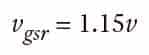
- The safety retarding force is insufficient to stop the overspeeding car but sufficient to reduce the car speed from safety-application speed so that it contacts the oil buffer at a speed not exceeding the buffer speed rating, Vgsr.
The relationships between rated speed, governor tripping speed and safety application speed are:
and
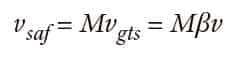
where the coefficients, β and M, are specified in Table 7.
Car Positions During Free-fall and Combined Safety and Oil Buffer Stopping
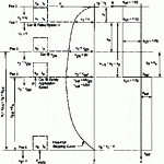
The motion of the car is discussed in reference to the positions shown in Figure 10 and as explained in Table 7. The general analysis is presented for the case of a free-fall due to suspension failure, followed by combined FGC-safety and oil buffer stopping. In Figure 10, the various car positions are shown by dashed-line rectangles at the left of the figure, the velocity-versus-distance (v-s) curve in the middle diagram, and the accelerations and retardations in the right diagram by the a-t curve.
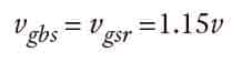
From Figure 10 and Table 7, it is seen that the buffer rated striking speed are given as:
in accordance with A17/B44[6] Rule 2.22.4.1.1 for buffers used for normal rated speed and A17/B44 Rule 2.22.4.1.2, where a terminal speed reducing device is used in conjunction with reduced buffer strokes. For purposes of this analysis, the buffer striking speed, vgbs, will be whichever of the two conditions, i.e., full buffer stroke or reduced buffer stroke, is applicable.
A17/B44[6] Rule 2.22.4.7.1 requires oil buffers to be type-tested and certified in accordance with the requirements of A17/B44 Rule 8.3.2 and certified per 8.3.1. The maximum striking (impact) speed the buffer can sustain is required to be put on the buffer marking plate per Rule 2.22.4.11(a).
The buffer striking speed cannot exceed the maximum speed for which the oil buffer was designed and rated, i.e.,
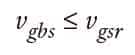
For purpose of the following analysis, the buffer striking speed will be taken at its maximum value, so that Equation 39 becomes:
Motion Analysis: Stopping Freely-Falling Car by FGC Safety and Oil Buffer
From Figure 10 and Table 8, the incremental motions of the car are analyzed from the onset of descending car motion until the completion of the combination safety and oil buffer stop. The general analysis is presented below.
The general equation for rectilinear motion with constant acceleration is given as:
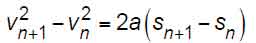
Pos 0 to Pos 1
Since the motions will only be tracked once the car reaches rated speed at Pos 1, there is no equation of motion necessary to describe the car motion from Pos 0 to Pos 1.
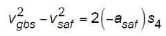
Pos 1 to Pos 2
The motion of the car from Pos 1 to Pos 2 is found from the following:
Substituting the appropriate values in the vertical distance between Pos 1 and Pos 2 yields:
from which the distance over which the car speed increases from rated speed to governor tripping speed is:
In the free-fall mode, the runaway car acceleration is equal to the acceleration due to gravity, so that:
Substituting Equation 48 into Equation 47 yields:
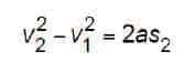
Pos 2 to Pos 3
The motion of the car from Pos 2 to Pos 3 is found from the following:
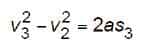
Substituting the appropriate values in the vertical distance between Pos 2 and Pos 3 yields:
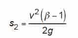
from which the distance over which the car speed increases from governor tripping speed to safety application speed is:
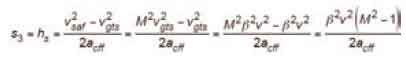
Substituting Equation 48 into Equation 52 yields:
Pos 3 to Pos 4
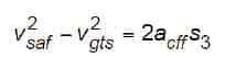
The motion of the car from Pos 3 to Pos 4 is found from the following:
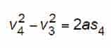
Substituting the appropriate values in the vertical distance between Pos 3 and Pos 4 yields:
It should be noted that throughout this article, safety retardations have been expressed as positive absolute values. However, since both accelerations and retardations are being evaluated in this analysis, each must be differentiated by its sign. Therefore, asaf is expressed as a negative value in Equation 51 since, according to the coordinate system shown, accelerations are positive, and retardations are negative, so that Equation 55 becomes:
from which the distance over which the car speed increases from governor tripping speed to safety application speed is found by substituting Equations 38 and 39 in Equation 56:
from which:
Since the sign convention has been addressed, it is only necessary to use the positive absolute values for asaf
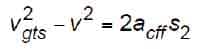
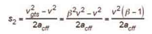
Pos 2 to Pos 4
From Figure 10, the distance from the point at which governor tripping speed, vgts, is attained until the safety has reduced the car speed to buffer striking speed, vgbs, is equal to:
Substituting (53) and (58) in (59) yields:
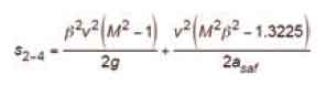
from which the distance from the point at which governor tripping speed, vgts, is attained until the safety has reduced the car speed to buffer striking speed, vgbs, is:
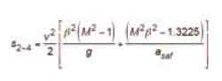
It can be seen that Equation 61 gives the same numerical result as given by A17 Interpretation 86-2, Equation 24.
Referring to Figure 10, it is seen that, to affect a combination safety and buffer stop, bringing the car to a full stop, full activation of the safety must occur not lower than the distance,
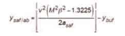
Substituting Equation 58 into Equation 62 yields:
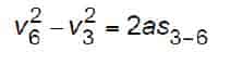
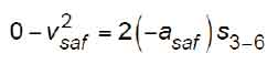
Free-fall Stopping by Safety, on Its Own
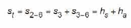
From Figure 11, it is seen that, once the safety has fully applied at Pos 3, the free-falling car is slowed down under an impressed retardation, asaf, until the car speed has been reduced to v6 = vc = 0 at Pos 6 where the car is fully stopped. The slowdown and stop by the safety, on its own, will impart a constant retardation, asaf, on the car from Pos 3 down to Pos 6, which will result in a stopping distance, st, measured from Pos 2 to Pos 6. The events related to the car positions from Pos 2 to Pos 6 will be as shown in Table 9.
Motion Analysis: Stopping Free-falling Car by FGC Safety, on Its Own
The general equation for rectilinear motion with constant acceleration was given by Equation 44 as:
Pos 2 to Pos 3
The motion of the car from Pos 2 to Pos 3 was found from Equation 53 as:
Pos 3 to Pos 6
The motion of the car from Pos 3 to Pos 6 is found from the following:
Substituting the appropriate values into the vertical distance between Pos 3 and Pos 6 yields:
Substituting Equation 38 into Equation 65 yields:
Pos 2 to Pos 6
The total distance from the point at which the governor is mechanically tripped to the point at which the car is stopped by the Type B Safety, on its own, is:
Substituting Equations 53 and 66 into Equation 67 yields:
From which:
Substituting Equation 48 into Equation 69 yields the total distance from the point at which the governor is mechanically tripped to the point at which the car is stopped by the Type B safety, on its own, as:
With the exception of the symbols used in this article and those used in A17 Interpretation 86-2, the derived equations are the same.
Dimensional Conversions
SI is the basis for worldwide standardization of measurement units. It was adopted by the ASME A17 Standards Committee as the primary dimensional system for inclusion in the ASME A17.1-2000 Safety Code for Elevators and Escalators.[5] The term “SI” derives from the official name in French, Système International d´Unités. The reference standards used in A17/B44[6] are listed in the last section.[10-13]
Abbreviations, Acronyms and Terms
For the purposes of Parts 1 and 2 of this article, the following apply:
A17/B44 = ASME A17.1/CSA B44 Safety Code for Elevators and Escalators
DWT = double-wrap traction
e-Stop = emergency electrical stop EU = European Union
FGC = flexible guide-clamp safety
GOS = governor overspeed switch
GTS = governor tripping speed
ISO/TC 178 = International Organization for Standardization Technical Committee 178
MSD and MD = A17 Mechanical Safety Devices and Machine Design Committee
ms = millisecond
mps = meters per second
NBS = National Bureau of Standards NEII = National Elevator Industry, Inc. SI = International System of Units
SOS = Safety operating switch
UL = Underwriters Laboratories
WG4 = ISO/TC 178 Working Group 4
The meaning of terms not specifically defined in this article shall be as defined by technical books and publications, codes and standards, and/or by collegiate dictionaries in the sense that the context implies.
Notations and Nomenclature
a = average safety stopping retardation of the car at safety application (general) (used in A17 Interpretation 86-2) (mps2 or fps2)
abuf = average oil buffer retardation (mps2 or fps2)
abuf/saf = average stopping retardation due to combination safety and oil buffer stop (mps2 or fps2)
ac = average acceleration/retardation of car (mps2 or fps2)
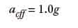
acff = average acceleration of free-falling car (mps2 or fps2), acff = 1.0g
acomb = average retardation of car due to combined safety application and e-stop (mps2 or fps2)
asaf = average retardation of car due to safety application only (mps2 or fps2)
C = car weight (lbf )
f(v) = a function of speed
F = total safety retarding (braking) force from all safety assemblies (general) (N or lbf )
Fbuf = buffer retarding force during buffer retardation (N or lbf )
Fbufstatic = static buffer force after combination safety and buffer stop (N or lbf )
Fstatic = static safety holding force after safety stop (N or lbf )
g = acceleration due to gravity (9.80665 mps2 or 32.17405 fps2)
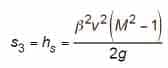
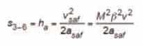
ha = distance car descends from the speed point, vsaf, at which safeties are fully applied to the point at which the car is brought to a stop. Per A17 Interpretation 86-2, ha = s3-6 (m or ft.).
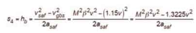
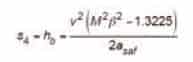
hb = distance car descends from the speed point, vsaf, at which safeties are fully applied to the speed, vgsr, for which the buffer is designed (m or ft.). Per A17 Interpretation 86-2, hb = s4.
hs = distance car descends in free-fall from point of reaching governor tripping speed, vgts, to the speed point, vsaf, at which the safeties are fully applied (m, or ft). Per A17 Interpretation 86-2, hs = s3.
ksaf = rated load ratio during A17/B44 overspeed test (ksaf = 1.0) (dimensionless)
L = rated load (weight) (lbf )
M = constant term used to describe safety activation speed as a function of governor tripping speed (dimensionless); also used for mass and moment of force.
Mmax = maximum value for the constant M (dimensionless)
Mmin = minimum value for the constant M (dimensionless)
mC = mass of car (kg)
mL = rated load (mass) (kg)
mW = mass of counterweight (kg)
Rh = weight of single run of suspension means (lbf )
s = distance (general term) (m or ft.)
s = safety stopping distance (general term) (m or ft.)
s = per A17 Interpretation 86-2, s = s3 + s4 (m or ft.)
sbs = car buffer stroke (mm or in.), where sbc = s5.
sgbs1 = distance car travels down from rated speed to buffer striking speed, vgbr, during free-fall (m or ft.)
sn = initial distance car travels at point, n, at time, tn, (general) (m or ft.)
sn+1 = final distance car travels at point, n+1, at time, tn+1, (general) (m or ft.)
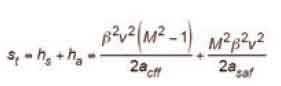
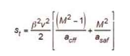
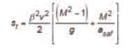
st = total vertical distance from the point at which the car reaches governor tripping speed, vgts, at Pos 2, until the car has fully stopped at Pos 6 (m or ft.) (st = s2-6 = s3 + s3-6)
s0 = initial distance car travels (general) (m or ft.)
s1 = distance car descends in free-fall from the point where the suspension ropes fail to attain rated speed, v, from Pos 0 to Pos 1 (m or ft.)
s1-3 = distance car descends in free-fall from point of reaching rated speed to the speed, vsaf, at which the safeties are fully applied (m or ft.)
s2 = distance car descends in free-fall from point of reaching rated speed to the point at which governor tripping speed, vgts, is attained (m or ft.)
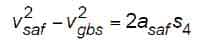
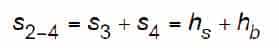
s2-4 = distance car descends from the point at which governor tripping speed, vgts, is attained, to the point at which the safety retardation reduces the car speed to the speed for which the oil buffer is designed, vgsr (m or ft.)
s3 = distance car descends in free-fall from point of reaching governor tripping speed, vgts, to the speed point, vsaf, at which the safeties are fully applied (m or ft.). Per A17 Interpretation 86-2, hs = s3.
s3-6 = distance car descends from the speed point, vsaf, at which safeties are fully applied to the point at which the car is brought to a stop. Per A17 Interpretation 86-2, ha = s3-6 (m or ft.)
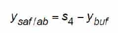
s4 = distance car descends from the speed point, vsaf, at which safeties are fully applied to the speed, vgsr, for which the buffer is designed (m or ft). Per A17 Interpretation 86-2, hb = s4.
S5 = buffer stroke (m or ft.), where s5 = sbs.
t = time duration for an event (general) (ms or s.)
t0 = initial time at onset of free-fall motion = 0 (ms or s.)
t1 = time duration for the car to move from Pos 0 to Pos 1 (ms or s.)
t2 = time duration for the car to move from Pos 1 to Pos 2 (ms or s.)
t3 = time duration for the car to move from Pos 2 to Pos 3 (ms or s.)
t4 = time duration for the car to move from Pos 3 to Pos 4 (ms or s.)
t5 = time duration for the car to move from Pos 4 to Pos 5 (ms or s.)
v = speed (velocity) of the car (general) (mps or fpm)
v = rated speed (velocity) (mps or fpm)
v = rated speed (velocity) (mps or fpm), v = v1
vc = car speed (velocity) (general) (mps or fpm)
vf = speed of car when suspension fails or an overspeed starts (mps or fpm)
vgbs = car speed at initial contact with buffer, i.e., buffer stroking speed (general) (mps or fpm)
vgsr = maximum speed for which the buffer is designed and rated (general) (mps or fpm)
vgts = governor tripping speed, as calibrated (mps or fpm)
vn = velocity of car at point, n, at time, tn (general) (mps or fpm)
vn+1 = velocity of car at point, n+1, at time, tn+1 (general) (mps or fpm)
vsaf = car speed at which safety applies full retarding force (mps or fpm)
v0 = initial speed (velocity) of a body (mps or fpm)
v1 = rated car speed as car free-falls (mps or fpm), v1 = v
v2 = governor tripping speed (mps or fpm), v2 = vgts
v3 = safety application speed (mps or fpm), v3 = vsaf
v4 = speed for which buffer is designed (mps or fpm), v4 = vgbs
v5 = car speed at end of buffer stroke in combination safety and buffer stop (mps or fpm)
W = weight of counterweight (lbf )
ybuf = vertical distance from the lower terminal landing to the top of the car oil buffer in its fully extended position (m or ft.)
ysaf/ab = vertical distance from the lower terminal landing to the lowest point at which the car in free-fall descent reaches safety application speed, vsaf, and the resulting safety stopping distance by the safety, on its own, reduces the car speed to buffer striking speed before compressing the buffer (m or ft.)
α = available traction (tractive effort) between drive sheave and suspension means (dimensionless)
β = constant term used to describe governor tripping speed as a function of rated speed (dimensionless)
βmax = maximum value for the constant, β (dimensionless)
βmin = minimum value for the constant, β (dimensionless)
> = greater than
< = less than
≥ = equal to or greater than
≤ = equal to or less than
>>= significantly greater than
<<= significantly less than
→ = approaches (e.g., vsaf → vgbs; i.e., the safety application speed approaches the car speed at initial contact with buffer)
Learning-Reinforcement Questions
- Use the below learning-reinforcement questions to study for the Continuing Education Assessment Exam available online at www.elevatorbooks.com or on p. 127 of this issue.
- Why is it important to have reviewed A17 Interpretation 88–2?
- Why is it important to have reviewed the A17/B44–2016 Requirements and the A17.2–2014 Items for the design and testing of Type B safeties and overspeed governors, respectively, listed in Table 1 in Part 1 of this series (EW, April 2018)?
- Why is it important to have a basic understanding why the A17 committees were asked by the European code writers three decades ago to reexamine the need for Type B safeties, designed and manufactured in the U.S., to be tested in the free-fall condition and certified by independent entities?
- Why is it important to have a basic understanding of the motions of the elevator once a free-fall overspeed is detected?
- Why is it important to have a basic understanding of free-fall performance of Type B safeties in the free-fall mode, stopping the car by the safeties, on their own?
- Why is it important to have a basic understanding of the operational steps of the mechanical systems, which cause time response delays in the governor and safety application?
- Why is it important to have a basic understanding of the incremental speed increases during the governor and safety activation process due to time response delays?
- Why is it important to have a basic understanding of the operational characteristics of a pit oil buffer in the retardation and stopping of a descending car?
- Why is it important to have developed a basic understanding of free-fall performance of Type B safeties in the free-fall mode, coupled with an oil buffer stop?
- Why is it important to have a basic understanding of the arguments for and against free-fall protection for Type B safeties three decades ago?
-

- Figure 9: Your author’s article (EW, July 1988)
-
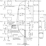
- Figure 10: Motion diagram for combined safety and buffer stop for stopping of free-fall car
-
- Figure 11: Motion diagram for stopping free-falling car by Type B safety, on its own
-

- Table 7: Coefficients for free-fall stopping
-
- Table 8: Car positions during free-fall and combined safety and oil buffer stopping
-

- Table 9: Car positions during free-fall safety stopping
References (Parts 1 and 2)
[1] A17 Interpretation 86-2; A17 Main Committee Approval, 03/11/87; A17 Elevator and Escalator Interpretations, Interpretations Book No. 11, November 1986-April 1987.
[2] Gibson, G.W., “Stopping Capability of Safeties”, ELEVATOR WORLD, July 1988, p. 98-103.
[3] A17 Interpretation 01-60; A17 Committee Approval, 01/09/02; A17 Elevator and Escalator Interpretations, Interpretations Book No. 25, June 2001-June 2002.
[4] ASA A17.1-1955 American Standard Safety Code for Elevators, Dumbwaiters and Escalators
[5] ASME A17.1-2000 Safety Code for Elevators and Escalators
[6] ASME A17.1-2016/CSA B44-16 Safety Code for Elevators & Escalators
[7] ASME A17.1/CSA B44 Handbook, 2013 Edition
[8] EN 81-1: 1998 + A3: 2009, Safety Rules for the Construction and Installation of Lifts, Part 1: Electric lifts
[9] EN 81-20: 2014 Safety rules for the construction and installation of lifts — Lifts for the transport of persons and goods-Part 20: Passenger and goods passenger lifts
[10] IEEE/ASTM SI 10-1997 Standard for the Use of the International System of Units (SI): The Modern Metric System
[11] ASME Guide SI-1, Orientation and Guide for Use of SI (Metric) Units
[12] IEEE/ASTM SI 10-2016, American National Standard for Metric Practice
[13] CAN/CSA-Z234.1, Canadian Metric Practice Guide (Latest Edition).
Get more of Elevator World. Sign up for our free e-newsletter.


