Adjustable Connections to Concrete Elevator Shafts
May 1, 2013
Halfen GmbH, Germany
ABSTRACT
Accurate positioning of elevator components within the shaft can be critical to ride quality and safety. The adjustment offered by cast-in and adjustable anchor channel connections can enable the accurate positioning of elevator guide rails, divider beams and elevator doors to concrete structures. In selecting the appropriate product the designer may need to review the static, dynamic, and seismic loading capacities required from connections, in addition to installation issues.
1. Introduction
There is no doubt that much of the news focus within the elevator industry revolves deservedly around the high-tech advances in equipment, control systems, and methods of assessing and designing for maximizing efficiency of performance. Developments in these areas have revolutionized the performance of the vertical transportation industry, to match the exacting design requirements of high rise structures, energy usage, and optimum passenger experience.
One of the less publicly discussed engineering subjects is the method used for anchoring essential pieces of equipment into the elevator shaft. This is a more mundane subject that has to be addressed for every elevator installation. Mundane it may be, but it is extremely important if it is viewed with regard to installer and passenger safety; ride quality; connection life expectancy; and the long term reliability of the vertical transportation system. In assessing anchoring options the system designer basically has the choice of three main methods of connection to concrete elevator shafts – welded connections to embedded plates; drilled bolts; and bolted connections to cast-in adjustable channels. It is this latter method that is the main subject of this paper.
2. Product History And Concept
The use of cast in channels for connections in the elevator shaft began decades ago, and has spread globally as one of the favoured methods of anchoring to new concrete structures. Halfen, the market leader in hot and cold rolled channel systems, began business in 1929 in Germany, and over time has gradually expanded its market to most of the world. The hot and cold rolled channel systems produced by the company were developed in a wide variety of profile sizes to accommodate light to heavy duty load requirements. Meanwhile in North America lighter duty strut profiles originally developed as cold rolled metal framing systems in the late 1920’s were also being adapted to create cast-in embeds. Cold rolled strut systems are now widely produced by many manufacturers around the world largely based on a 1-5/8” (41mm) width of profile to varying quality standards. Strut style channels are typically converted for use in concrete by punching out the back of the channel and bending the material to form an “L” shaped anchor.
The basic method of using an anchor channel connection system to concrete is relatively simple. Prior to pouring the concrete, channels with anchors are nailed to the wooden formwork which is used to form the concrete structure. The channels have been filled with removable filler at the factory to prevent concrete entering the channels during the concreting process. The channels are located on the formwork in the area where connections are required, and the concrete is poured.
After the concrete has hardened, the formwork is removed leaving the opening to the channel exposed on the surface of the concrete. The channel is now ready to receive the connections required to anchor components to the surface of the concrete. The Halfen style of cast-in channels are normally anchored to using T-headed bolts, which are face entered into the channel after removing the filler. The T-bolts are turned ninety-degrees to lock in position, and are marked with a head orientation line on the shank of the bolt to give a simple visual check of correct installation. Strut systems tend to use channel nuts which are more difficult to visually check for orientation and thread engagement with mounting bolts because they are usually hidden behind the connection brackets.
3. Product Application Within The Elevator Shaft
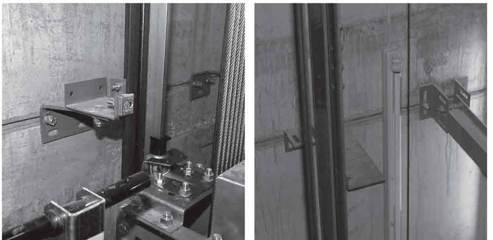
The primary uses of cast-in channel connections in the elevator shaft are for connections relating to guide rails and door equipment. In most applications the adjustment provided by the cast-in channel is complimented by using slotted brackets to provide additional positioning adjustment in other planes. Consequently this combination of cast-in channels and slotted brackets offer the installer and designer a simple and safe method of ensuring accurately positioning the elevator car and counter weight guide rails within the shaft. The accuracy provided gives the opportunity to maximise ride quality, and minimise eccentric loading on guide rail components.
Similarly door gear is regularly connected to cast-in channels in order to accurately position anchor points at the head and threshold. Structural steel components such as divider beams, and services are accurately secured into the elevator shaft using this method.
The long-term accessibility of the channel once it is cast into the shaft wall enables the rapid replacement of worn components, and easy upgrading of apparatus to update the installation. The T-bolts used for the connections are simply removed for replacement or relocated to new positions in the cast-in channels. A wide selection of T-bolt diameters, lengths, steel grades and finishes are available to fit each type of channel profile, so multiple connection conditions or later changes in either connection spacing or the mechanical requirements can normally be easily accommodated.
Compared to other methods of anchorage the cast-in channel concept can provide a number of safety and reliability advantages in the elevator shaft compared to other methods of connection that might be considered. Firstly there is no drilling of concrete required to install connections, which means minimal noise, no silica dust, and no vibrating power tools for the installer. Limiting worker exposure to excessive noise, silica dust, and hand-arm vibration is rightly attracting the attention of various health and safety bodies and designers around the world, due to evidence of possible serious health problems associated with long-term exposure. Within the confined space of an elevator shaft the dangers of noise and dust to the installer can be further magnified. The use of cast-in channels can also replace the process of welding to steel plates embedded in the concrete and so reduce fire risks, burn/electrocution hazards and dangerous fumes within the elevator shaft.
Cast-in channels are installed with simple tools, and are inherently reliable because they are simple in concept and easy for supervisors to visually check. They can of course be misplaced, but normally when used in sufficiently long lengths to accommodate installation tolerances, they are a very reliable method of installation. Their use can avoid concerns over drill damage to the structure, or the competence of installers to drill the correct depth and diameter of holes for bolts, or make welds to embedded plates of sufficient quality for long term reliability. The supervision process is therefore much simpler.
4. Design Considerations
4.1 Overview
Halfen style cast-in channels are available in cold and hot rolled profiles and both these styles can provide excellent tension and shear load capacities for anchoring to concrete. The first task in product selection is to select the appropriate channel type according to the conventional tension and shear loads to be supported. Technical catalogues and software are available from the manufacturer to do this. The second task is to determine if the connections will be subject to any special loading such as dynamic cyclical loading, seismic loading, or impact loading.
4.2 Dynamic Loading
Within the elevator shaft the cyclical movement of the elevators on their guides and the actions of the door gear mean that most of the connections associated with these components are subject to dynamic loading. Although some installers use cold rolled channels in the elevator shaft, in general hot rolled channels are considered more applicable for these types of loads. Hot rolled channels typically have less stress within the profile, and have a more complete tested performance in dynamic conditions, that is also enhanced by a long history of use in the field. The graph below (figure 9.) shows the allowable dynamic amplitude of loads for a number of hot rolled profiles at 2 x 10⁶ cycles. The graph also shows complete allowable load amplitude curves for < 2 x 10⁶ cycles for two hot rolled profiles commonly used for elevator guide rail connections. These load values are based on empirical testing because in the past it has been very difficult to create a calculation model capable of accurately predicting fatigue performance in dynamic loading situations. A model giving reasonable predictors of performance > 2 x 10⁶ cycles on hot rolled channels is now available. The dynamic performance of the connection is obviously important for determining maintenance and safety issues over the lifetime of an installation, which will see millions of passenger journeys.
4.3 Longitudinal Loading
An advantage of hot rolled channels is their thicker lip design (see figure 8), which enables high torque values to be applied to T-bolts without crushing the channel lips. Higher torques can enable higher longitudinal loads in the direction of the channel to be supported. This can be important for guide rail installations that may require the support of higher side loads. High tensile T-bolts are available for this purpose, and additionally nibbed T-bolts can be selected to physically bite into the lip of channel, when high torque is applied. The biting action of the nib provides mechanical resistance to longitudinal loads applied to the channel.
Hot rolled channels with serrated lips and matching serrated T-bolts are also available. These allow more significant longitudinal loads up to the tension and transverse shear capacity of the channel to be supported. Their dynamic loading is similar or a little better than the standard range of hot rolled channels. The mechanical interaction between the teeth on the bolt and channel lip allow very high side loads on the rail to be accommodated (design resistances of over 30 kN [6,750 lbs.] per T-bolt connection are possible). This feature also makes the serrated style of channel suitable for connections where vertical tolerance and significant vertical loading are required, because this can be achieved by orienting the length of the serrated channel in the vertical plane rather than the horizontal. Secondary steel work connections can be an example of this type of connection requirement.
4.4 Seismic and High Impact Loading
Special testing has recently been completed simulating the effects of internal and external explosions or earthquakes on the connection performance of hot rolled channels while cast into high security concrete structures. The testing was orientated towards the connection requirements of the nuclear industry, but data obtained also has application outside this sector when extreme loading considerations have to be considered by the designer. The tests were carried out in concrete with cracks that were oscillated in widths from 1.0 mm to 1.5 mm over 10 cycles at 0.2 Hz while the channel was being constantly loaded. After the load cycling a progressively increased load was then applied to the channel with the crack widths held at 1.5mm until ultimate loads were achieved. The HZA-PS range of toothed hot rolled channels, which was developed from this testing, consists of channel profiles with serrated lips combined with special high performance anchors to cope with the extensively cracked concrete that results from an extreme event. This range can provide design resistances of over 30 kN [6,750 lbs.] per T-bolt in any direction.
4.5 Connections to Thin Metal Deck Floor Slabs and Steel Structures
In steel structures the designer may face situations where door gear and guide rails will need to be anchored to the edge of relatively thin floor slabs rather than to a continuous concrete shaft walls. Conventional hot rolled channels work very well in thin concrete achieving good loads with small concrete edge distances, and can be provided pre-connected to the permanent metal edge trim of the slab. The position of the profiled metal decking in the slab can cause a reduction in the available concrete to distribute the loads applied to the channel. In situations where the load capacity has been reduced excessively, or when particularly high loads are required from the slab connection, the normal channel anchors are either modified, or additional reinforcement is added to the available concrete around the anchor. On some occasions hot rolled channel profiles are welded to the structural steel instead of being castinto the concrete. This method of connection is normally an option for refurbishment installations; or if concrete is not being used in the vicinity of the lift shaft; or where the construction schedule precludes the use of channels cast into the concrete.
5. Project Example
Tower 1 World Trade Center in New York City will be an iconic building with an emotional history. It is currently under construction and is one of the new structures located on the site of the previous World Trade Center, which was destroyed by terrorists in the 9/11 attacks of 2001. When completed the building will be 104 storeys and with its spire will stand 1776 feet tall, a symbolic reference to the year in which the USA gained its independence. It will become the tallest building in the USA, and the structure will be serviced by 71 elevators provided by ThyssenKrupp Elevator Americas. Five of these elevators are extremely high speed operating at 9 metres per second (2,000 feet/minute).
In 2005 discussions began with the architect SOM, structural engineer WSP Cantor Seinuk, and the Port Authority of New York New Jersey, regarding the design of connections within the elevator shaft. ThyssenKrupp Elevator Americas also became involved in the design discussion at a later stage. In addition to the requirement for accurate installation for the guide rails to ensure passenger ride quality, a major design consideration the preference to avoid drilling into the structure. This was because of the extremely high concrete strength being used, and the high concentration of steel reinforcement located in the structure. There was a concern that drilling such hard concrete would be very difficult, and there was a risk that the drilling process could damage the closely packed steel reinforcement. After design consideration of the static and impact loads that the connections would be required to support, cast-in hot rolled channels were selected as the anchoring method to be used in the elevator shaft. The design for all areas of the shaft was concluded in 2008, by which time stainless steel cast-in channels had also been selected to support stainless steel panels in the lobby areas. Delivery of cast-in channels began to some areas of the construction in the later part of 2007.
In all 7,000 hot rolled cast-in channels were used on the project with delivery completed in the first half of 2010. T-head bolts in two diameters were used to connect the lift shaft guide rails to the cast-n channels. The installation of the guide rails began in the lower areas of the structure in 2008 with most of the remaining guide rails being installed during 2010.
6. Conclusions
As with other aspects relating elevator technology, the science of concrete connections has also progressed over the decades. Products and engineering have developed providing increasing levels of reliability and performance to keep pace with the design requirements of modern structures. Our understanding of connection technology continues to evolve and new methods of calculation provide increasingly accurate predictors of performance in varying conditions. Meanwhile, the continuing simplicity of the cast-in hot rolled anchor channel concept enables the accuracy of calculated design performance to be consistently applied in the field, and this can be a major factor in their selection for critical connections in the elevator shaft.
7. Acknowledgements
The writer gratefully acknowledges the kind cooperation of ThyssenKrupp Elevator Americas with regard to the Tower 1 World Trade Center project example presented in this paper.
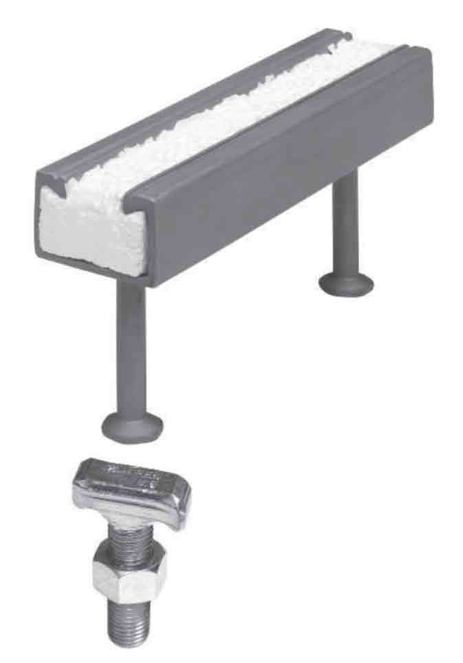
Figure 1: Halfen style hot rolled anchor channel with integrated anchors, removable filler, and typi-cal twist-in T-bolt connection. 
Figure 2: Strut style 1-5/8” (41mm) wide cold rolled framing channel with typical channel nut connection. 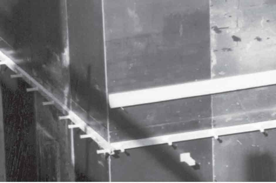
Figure 4: Typical hot rolled anchor channel connections for guide rails and divider beams 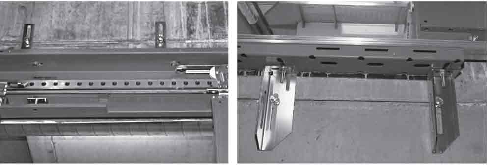
Figure 5: Typical connections at door openings illustrate the range of positional adjustment possible for door apparatus. 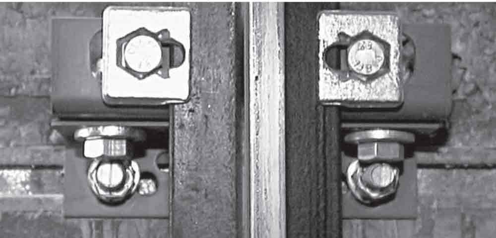
Figure 6: Vertical lines on the end of the channel T-bolts provide an easy visual check that the T-bolts are correctly installed in the channel. 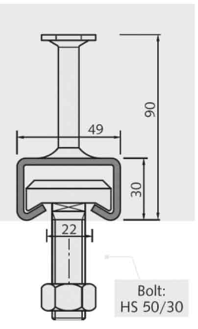
Figure 7: Typical cold rolled channel with uniform material thickness and characteristically round corners 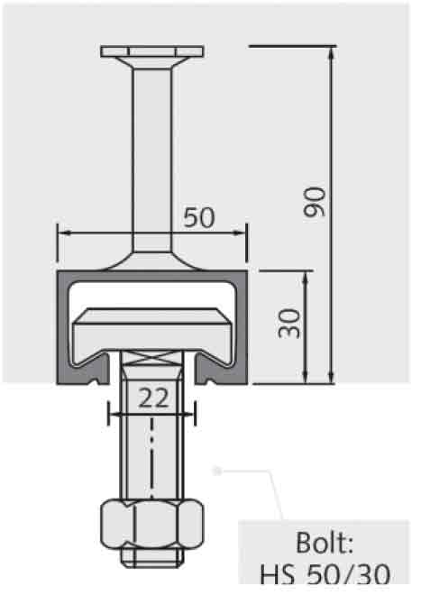
Figure 8: Typical hot rolled channel with characteristically thicker mate-rial at the lips and square corners 
Figure 9: Allowable range of dynamic load amplitudes for hot rolled channels 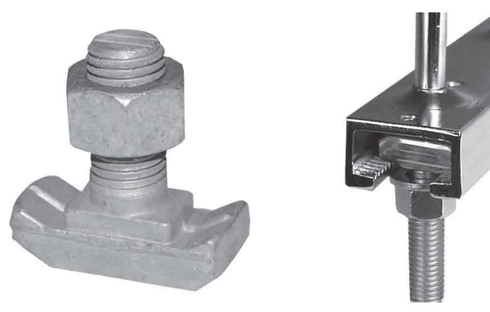
Figure 10: High tensile nibbed bolt plus serrated hot rolled channels and matching serrated T-bolts for high longitudinal loading. 
Figure 11: Testing arrangement of hot rolled anchor channel loaded in constantly fluctuating crack widths. The graph illustrates low deflection during cyclic testing and then stable progression to ultimate load while the concrete cracking at the anchor position is held at the maximum 1.5mm width 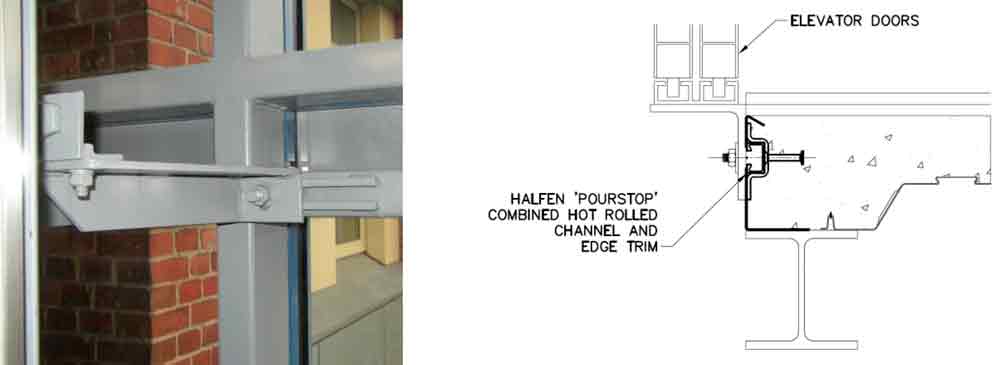
Figure 12: Typical connection options for elevator connections in steel structures 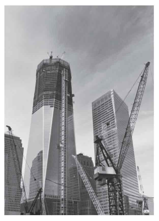
Figure 13: Tower 1 World Trade Center New York City under con-struction
Get more of Elevator World. Sign up for our free e-newsletter.

