Alternative Testing for Escalators and Moving Walks
May 1, 2018
Requirements for escalator and moving-walk speed have appeared in the ASME A17.1/CSA B44 standards since 2000 (Requirements 6.1.4.1 and 6.2.4.1). The A17.1 code, prior to harmonization in 2000, contained requirements for escalator speed since 1921 (Rule 610a). The maximum permitted speed of an escalator was reduced from 125 to 100 fpm in the 2000 edition of the A17.1/B44 harmonized code. Moving-walk speed is based on the angle of inclination and width of the treadway. (See A17.1/B44 Table 6.2.3.7.)
Retardation requirements for escalators were introduced in the 1983 Supplement B to the 1981 edition of the A17.1 code (Rule 804.3a) as a brake requirement. Similar requirements were introduced for moving walks in the 1988 Supplement A to the 1987 edition of A17.1 (Rule 904.3).
A17.1/B44 Part 8, Section 8.10.4.1 (8.10.4.1.1(c)(1) calls for testing the speed of the escalator or moving walk. Suggested test methods are provided in ASME A17.2 items 7.14 and 9.14 for escalators and moving walks, respectively.
The retardation of the escalator or moving walk is a function of brake torque. A17.1/B44 Part 8, Section 8.10.4.1 (8.10.4.1.1(s)(1) calls for testing brake torque on the escalator or moving walk. Requirement 8.10.4.1.2 (8.10.4.1.2(d) for internal inspection and tests also calls for verification of the brake torque for both escalators and moving walks. For escalators and moving walks with variable-torque brakes, the minimum no-load stopping distance is measured. Additional information is provided in A17.2 Items 8.4 and 10.4 for escalators and moving walks, respectively.
This article will explain the relationship between the stopping distance and the retardation of the escalator or moving walk at any determined speed.
Sophisticated equipment for the measurement of various parameters and characteristics is often not available, and the inspector, investigator or other personnel must resort to alternative testing to determine those parameters. We use the term “determine,” because direct measurement of the parameter may not be possible, but direct measurement of one or more factors that comprise the parameter is easily achievable.
Speed
Speed, or velocity, is determined by the measurement of distance, s, over a period of time, t. The average speed or velocity of an object is directly proportional to its change of position and indirectly proportional to the change of time during which the object travels. Engineers and technical-school students express this physics relationship as:

This is written mathematically as:
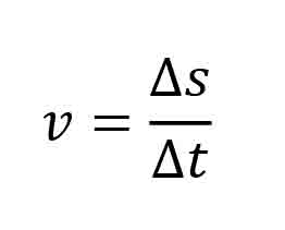
where v is the average velocity or speed of the object, expressed in units of length per units of time; Δs is the distance the object travels or its change in position expressed in units of length; and Δt is the time it takes to traverse the distance, expressed in units of time.
With this basic information, the speed or velocity of an escalator or moving walk can be determined by measuring the distance an object on the escalator or moving walk travels over a period of time. On a traditional, code-compliant escalator, the step has a nominal tread depth (front-to-back dimension) of 16 in. (406.4 mm). Ten steps would extend 160 in. (4,064 mm). If we measure the time it takes 10 steps to travel past a fixed point on the escalator and divide that time into 160 in., we will determine the speed of the escalator. The time we would traditionally measure would be in seconds using some variety of stopwatch, clock, smartphone or other device to measure time. If that time measured, for example, 9 s., the speed measured would be:

Since the traditional and conventional measure of the speed of an escalator is expressed in feet per minute, we should convert the speed given above from inches per second to feet per minute. (12 in. = 1 ft., and 60 s. = 1 min.)
We can multiply the speed determined above by any or all of the values expressed above and still arrive at the same value for the speed but expressed in different terms. Use this equation to convert the units:

from which:

Rewriting the expression and substituting numerical values:

This value would be rounded to 90 fpm.
Realizing that 160 in. is comprised of 10 steps (chosen as a constant) and that the time for the steps to traverse 160 in. varies with the speed of the escalator, this is the value we are to determine. Therefore, to determine the speed of the escalator, we measure the time it takes 10 steps to pass a given point on the escalator and divide that time, in seconds, into 800 to get the speed in feet per minute. In the expression above, 9 s. is the variable, so we can provide an equation to determine the speed of the escalator in feet per minute as:
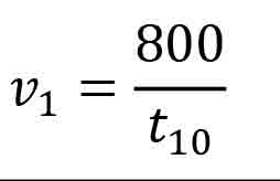
where t10 is the time in seconds for 10 steps to pass a fixed point on the escalator, and v1 is the speed of the steps in feet per minute.
Experience indicates that a good fixed point to use as a reference is the comb segment line. The time should begin when a step enters the comb line (the line formed by the comb teeth, t0) and stop when the 11th step enters the comb line, t10. It is possible to use the same method to determine the speed where the steps exit from the comb segments, but entering the comb segments seems more convenient.
The diagram below shows 10 horizontal steps. In fact, only a few entering the comb are horizontal, and the rest are on the lower curve and incline. However, the linear speed of the steps is in unison along the direction of travel.
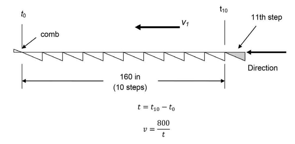
where v is the speed of the steps in feet per minute, and t is the time in seconds for 10 steps to pass under the comb segments.
Deceleration
A17.1/B44 contains requirements for the maximum average retardation or deceleration rate for an escalator stopping as a result of actuation of a safety device. Specifically, requirement 6.1.5.3.1(c) states:
“6.1.5.3.1 Escalator Driving-Machine Brake (c) Driving-machine brakes shall stop the down running escalator steps at an average rate not greater than 0.91 m/s2 (3 ft/s2) as measured over the total retardation time. No peak horizontal retardation value exceeding 0.91 m/s2 (3 ft/s2) shall have a time duration greater than 0.125 s (see Nonmandatory Appendix I, Fig. I-11).”
Attention is called to the reference to A17.1-2013/B44-13 Nonmandatory Appendix I, Fig. I-11. While not completely accurate, the graph gives a rough approximation for the stopping distance associated with a given escalator step speed at a stopping rate of 3 fps2. This is approximately 1/10 of a g, where 1 g is the acceleration due to gravity (32.2 fps2).
While the brake data plate provides the torque necessary to achieve the code-required retardation, it is often necessary or convenient to obtain a better approximation of the actual retardation of the escalator.
A method to determine the stopping rate or deceleration is to measure the stopping distance and calculate the stopping rate based on the speed of the escalator and stopping distance.
From the lower landing, with the escalator running in the down direction, actuate the emergency-stop button as the leading edge of a step approaches and intersects with the line formed by the leading edge of the comb segments. The step will proceed beyond the comb segment and stop.
Measure the length of the step tread remaining exposed and subtract that from 16 in., the depth of the step tread, to determine the stopping distance, which we will call s, expressed in inches. See the diagram below.
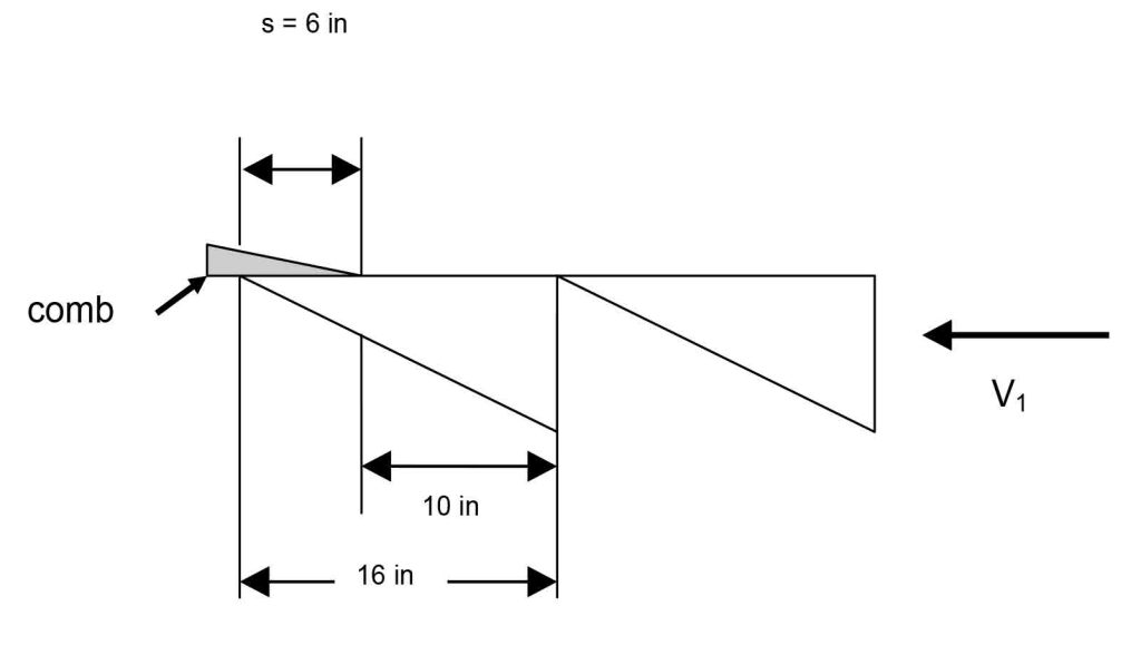
10 in. of the step remains when the escalator is stopped. 6 in. of the step has moved below the points of the comb segment. The stopping distance, s, is, then, 6 in.
The average retardation of the escalator can be determined based on knowing the escalator step speed, v1, and the step stopping distance, s.
The fundamental relationship between the velocity (speed) of a moving body, its stopping distance under an impressed constant retardation, is given by the standard motion equation:
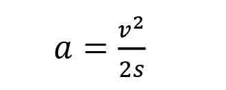
Substituting the variables used for our escalator example in Equation 1 yields:
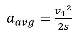
To solve this equation for the escalator retardation, the dimensional units must be consistent, so that Equation 2 becomes:

This equation is simplified to become:
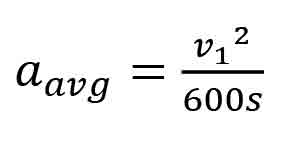
where aavg is the average stopping retardation of the escalator steps in their direction of travel, expressed in units of feet per second squared, s is the stopping distance of a step expressed in inches, and v1 is the escalator step speed as determined from the previous section “Speed,” expressed in terms of feet per minute. Examples of the use of this method are as follows.
For an escalator traveling at 100 fpm, the minimum stopping distance to achieve a retardation of 3 fps2 is:
Likewise, for an escalator traveling at 90 fpm, the minimum stopping distance to achieve a retardation of 3 fps2 is:
Summary
The speed of the escalator or moving walk is determined from Equation G. The retardation (deceleration) of the escalator is determined from Equation 4.
This article was used previously in NAESA International’s PROGRESS, October 2016.
Get more of Elevator World. Sign up for our free e-newsletter.


