An Apparatus for Testing Contacts of the Elevator Safety Circuit
Nov 1, 2013

by Yuandong Jian, Jiefeng Li, Yihui Ruan and Cheng Zhou
The safe operation of an elevator system is of primary importance. The system should work correctly and, above all, safely. For this reason, elevator systems employ a number of safety devices, one of which is the safety circuit. This device is one of the most important parts of an elevator’s electric safety system. The safety circuit extends from one safety device to another in the elevator shaft. The circuit typically consists of safety-device contacts and switches chained in series. The safety device includes a safety gear, an emergency trap door in the car roof, a speed governor, an oil buffer and more. If any of these devices interrupts the safety circuit, the elevator will stop.
During operation, repair and maintenance of an elevator, various failures may occur due to the interruption of elevator safety-circuit contacts. While repairing or maintaining an elevator, one may use specific tools to disconnect a safety circuit’s contacts. One of these contacts is the door-lock circuit.
It can be difficult to check the contacts of high-rise buildings’ hoistway doors one by one. Elevator technicians often spend much time checking contacts by bypassing part of the elevator safety circuit. The method this article introduces is intended to enable the quick investigation of failure contacts by elevator technicians. Its utility model is characterized by simple structure, small volume, high speed, low energy consumption and high reliability, all of which help ensure safe elevator operation. The following examples illustrate a typical solution.
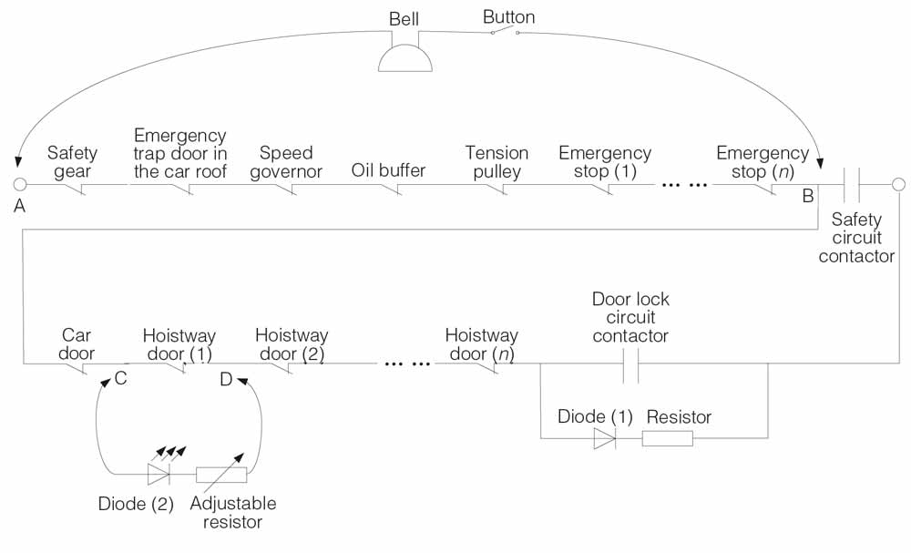
Figure 1 shows an electrical diagram of the elevator safety circuit. The apparatus for testing safety contacts of the elevator safety circuit is composed of two sets of electrical equipment. One includes three electric wires, two probes, and a button and bell. The other includes an adjustable resistor, two probes, an LED and three electric wires. The button and bell are connected in series with the wires. One probe is connected to the bell, and the other is connected to the button. The diode and adjustable resistor are also connected in series with the wires. One probe is connected to the LED, and the other is connected to the adjustable resistor.
Principle of Measurement
First, technicians must post a warning sign to alert people that the elevator is being repaired. One elevator technician in the machine room must keep in touch with another atop the elevator shaft. Second, a technician then presses the button in the machine room, the safety circuit closes, and the bell rings. The technician atop the car can operate the elevator at a low speed. When the car runs in a proper place (where the technician can conveniently check the failure contacts of the hoistway door), the technician in the machine room releases the button. The technician makes use of two probes of the latter electrical equipment to test whether the checked hoistway door circuit is intact, or there is a break. The LED emits light when a proper electric current passes through it. If the LED emits light, there is a break between the contacts of the hoistway door circuit checked by the car-top technician.
The failure can be eliminated easily and quickly. Because the maximum current, which flows through the diode, is only tens of milliamperes, there is not enough current to make the safety circuit conductive, and the elevator cannot run. The adjustable resistor is determined on the basis of the voltage of the safety circuit.
Get more of Elevator World. Sign up for our free e-newsletter.


