An Innovative Elevator System, Part One
Jan 1, 2017

A unique system detailed in 1870s Otis drawings, which serve as the first American depiction of a passenger elevator installation from cellar to penthouse.
The history of vertical transportation is filled with various “firsts” that identify key points in the development of modern elevator systems. The caution that should be used in evaluating any claim of a first has been addressed in previous articles: there is always the possibility that an earlier example may be awaiting discovery, and a true first occurrence of something may not have had any real or lasting significance. However, the seductive allure of discovering — or hoping you have discovered — a true first and presenting it to the world is a temptation that is difficult to resist. This two-part article concerns what appears to be the first publication in the U.S. of a set of drawings that depict a passenger elevator installation from cellar to penthouse. This investigation will examine the unique elevator system these drawings illustrated and their publication history in the early 1870s.
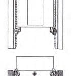
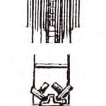
In 1869, Otis Brothers published a 70-page illustrated catalog that included detailed descriptions of the components and safety systems utilized in its passenger and freight elevators. Unfortunately, the catalog’s illustrations did not fully match the level of detail found in the text. The catalog featured 10 engravings that depicted four different hoisting engines, a typical ceiling-mounted belt-driven freight hoist, an automatic safety drum and a self-oiling pulley. Although two engravings did illustrate typical freight-hoist installations, neither provided a comprehensive view of an entire elevator system (Figures 1 and 2). The following year, the company corrected this deficiency with the publication of an eight-page pamphlet titled Description of Otis’ Patent Safety Passenger Elevator, which included a remarkable set of four drawings that offered readers a comprehensive view of one of its passenger elevator systems. The drawings consisted of a section through the elevator shaft from the cellar mechanical room to the penthouse (divided into two pieces via distinct break lines), a plan of the shaft that included the car and a partial plan view of the engine, and a plan of the penthouse sheaves and safety devices (Figure 3).
The pamphlet’s text provided a detailed description of the elevator and concluded with the observation that the design illustrated in the drawings was covered by 12 different patents. The latter fact was emphasized by references to individual system components, which included the company’s Patent Safety Lock Ratchet with Self-Locking Pawls, Patent Double Acting Safety Drum, Patent Automatic Stop Motion, Patent Self-Acting Brake and Patent Self-Oiling Loose Pulley. In addition to these components, the 1869 catalog also referenced Otis’ Patent Safety Sheave and Brake and Patent Safety Stop Connection. It is, in fact, possible to find a patent reference for almost every aspect of Otis’ 1870 elevator. A survey of the American patent record identified 17 patents awarded to members of the Otis family between 1860 and 1873, and, as noted above, 12 applied to Otis’ new elevator (Table 1). Although this end date falls after the pamphlet’s publication, it was selected because the final patent associated with this passenger elevator was issued in January 1873. This collection of materials (the 12 patents, the 1869 catalog and the 1870 pamphlet with its remarkable set of engravings) allows a thorough investigation of Otis’ Patent Safety Passenger Elevator.
The most well-known patent is, of course, Elisha Otis’ 1861 patent for his safety device that employed ratchets and pawls. The ratchets ran the full height of the shaft and served as guides for the car. The pawls were located on the car’s crossbeam and were released by the action of a spring. The 1870 Otis pamphlet described the ratchets as follows:
“These safety ratchets are of iron, very heavy, and having the strongest possible form. The lower ends have a firm bearing at the ground, and the two lines are extended perpendicularly to the highest point to which the car is to rise. The formation of the safety ratchets is such as to present a series of hook-shaped cogs to the pawls, attached to the car in close proximity thereto, and at intervals, limited to 3 in., throughout the entire distance of the run. These cogs, and the pawls which act upon them, have a peculiar conformation which ensures a perfect locking together of the two immediately following the slightest contact at the points and also renders a separation impossible, except through the instrumentality of the lifting rope, when properly connected and in order for work.”
The pawls were also made of “heavy iron,” and, when “forced. . . into contact with the safety ratchets” were “capable of sustaining the entire weight of the car” and its load. Because the ratchet teeth were spaced at 3-in. intervals, Otis also described this safety as “a mechanical device for reducing to 3 in. the distance which it is possible for the car at any time to fall, in case of breaking of the lifting ropes.” In the early 1870s, Otis produced a perspective drawing that illustrated the safety’s various components (Figure 4).
The ratchets also functioned as guides directing the movement of the car, and the areas flanking the ratchet teeth were described as “planed iron guides.” The top and bottom of the car was equipped with “running gear” composed of “wheels having peripheries of hard rubber. . . supported by iron flanges.” The wheeled running gear provided “perfect security against displacement,” as well as “sufficient elasticity to compensate for any slight variation in the relative positions of the guides” and ensured “a perfect bearing at all points, and entire freedom from any rattle or irregularity of motion.” The 1873 patent described the running gear having been:
“. . . designed to facilitate the noiseless operation of the vertically moving car in that class of elevators ordinarily used in hotels, warehouses, etc., and to insure much greater durability and more nearly perfect operation than has hitherto been found practicable with means hitherto devised for the purpose. It consists in the combination of fixed guides, having soft or elastic surfaces, with metal or other guide rollers or slides carried by the car, whereby the desired objects are effectually secured.”
The patent drawings closely resembled the depictions of the running gear found in the 1870 publication (Figures 5 and 6).
Five patents addressed various aspects of the steam-powered hoisting engine. Three patents concerned an engine brake directly connected to the engine’s start/stop control valve such that the brake was automatically released or engaged as the engine was started or stopped. The 1870 pamphlet included the following description:
“Combined with the engine and hoisting gear is a powerful brake, which is arranged to be brought into action and released from action simultaneously with the stopping and starting of the engine causing no unnecessary friction while the machine is running, but holding the entire apparatus immovable when it is required to stand at any point to receive or discharge loading or passengers.”
Otis’ U.S. Patent No. 68,783 concerned the operation of double-cylinder steam engines, which were typically “employed in the driving of an ordinary hoisting apparatus.” The company claimed that the efficiency of these engines depended “upon the control which is or may be had over the reversal of their actions for hoisting or lowering goods” and that its design provided “not only stability and durability. . . but an easy control. . . in a comparatively simple manner.”
The patent’s detailed technical description was somewhat simplified in the 1869 catalog:
“The engine is double cylinder and reversible; both cylinders being connected to a single shaft, with cranks set at right angles to avoid stopping on centers. Steam is permitted to pass to, and the exhaust to pass from the cylinders through a single valve, which is arranged to reverse the current or check the flow of steam by a simple movement or change in the position of same. The same movement which shuts off the steam from the cylinders also closes the exhaust orifice and renders further motion in the engine impossible. By this means, the car is always under control, both in the upward and downward movement, so long as the gearing and connections remain intact. The orifices in the reversing valve communicating to and from the cylinders, when the car is making the downward trip, are graduated to suit the changed relation and action of the loading, and any excessively rapid motion is thus prevented.”
In addition to ensuring the engine’s smooth operation, Otis’ U.S. Patent No. 83,725 addressed another key factor — noise:
“The leading feature or object of our invention is the running of hoisting-apparatus at what may be termed rapid velocity, without objectionable noise — an important consideration where the same is designed for hotel use and other purposes. To accomplish this, we employ endless screws, working in worm wheels.”
The 1870 pamphlet provided a detailed account of the implementation of a variation of this system, which appears to have not employed the worm gears referenced in the patent:
“To prevent the noise, as well as to avoid the jar necessarily attending the use of gearing at a rapid rate of speed, motion is communicated from the engines to hoisting gear (at the first remove) by means of a powerful belt. The second and third combinations, required in extending the connection to the large winding drum, are made by means of accurate machine-cut gearing, each change in train of gear being placed in duplicate, the teeth in the one being placed opposite the spaces in its counterpart. This method or doubling the bearing of the cogs, the perfection with which the wheels are made and adjusted, and the slow motion at which they run, affords the most perfect exemption from noise or jar under all circumstances. This precision in the mechanism of the engine and gearing is necessary in consequence of the fact that any inequality of movement at this point will be greatly multiplied in that of the car and produce a very disagreeable effect.”
A final engine safety feature was the Stop Motion, patented in 1865. This device was connected to the winding drum such that the car’s travel would not exceed preset limits (emphasis mine):
“. . . the patent Stop Motion. . . is adjusted to run through the exact number of revolutions required to make one trip between the bottom and the top of the hoistway, and then to stop the engine, after which it cannot start again without the act of the attendant, and then only in the opposite direction.”
The winding drum was described as made of iron, “carefully finished” and “grooved spirally to fit the coil of the wire cable when wound upon it, keeping the surfaces of the latter from contact and friction and unnecessary wear.” The results of these patents included Otis’ National and Metropolitan hoisting engines, with the hoisting engine depicted in the 1870 engraving resembling the National engine design (Figures 2, 7 and 8).
Part Two of this article will examine the remaining features of Otis’ 1870 Patent Safety Passenger Elevator, as well as the publication history of the drawings that constituted the first American depiction of a passenger elevator installation from cellar to penthouse.
-
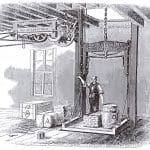
- Figure 1: Otis Freight Elevator (back cover, Otis Brothers & Co.’s Patent Safety Hoisting Machinery Illustrated Descriptive Catalog and Price List, 1869)
-
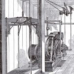
- Figure 2: Metropolitan Hoisting Machine (Otis Brothers & Co.’s Patent Safety Hoisting Machinery Illustrated Descriptive Catalog and Price List, 1869)
-
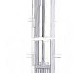
- Figure 3: Otis’ Patent Safety Passenger Elevator (Description of Otis’ Patent Safety Passenger Elevator, 1870)
-
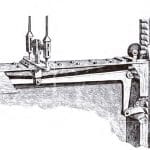
- Figure 4: Otis’ Safety Ratchet with Self-Locking Pawls (Otis Brothers & Co., early 1870s)
-
- Figure 5: Charles R. Otis, “Improvement in Guides for Elevators,” U.S. Patent No. 134,698 (January 7, 1873)
-
- Figure 6: Running Gear Elevator and Plan (Description of Otis’ Patent Safety Passenger Elevator, 1870)
-
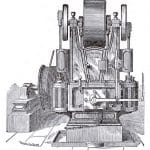
- Figure 7: National Hoisting Machine (Otis Brothers & Co.’s Patent Safety Hoisting Machinery Illustrated Descriptive Catalog and Price List, 1869)
-
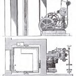
- Figure 8: Steam Hoisting Engine Elevation and Plan: automatic engine brake (P), leather belt (L), stop-motion (N) and winding drum (M) (Description of Otis’ Patent Safety Passenger Elevator, 1870)
-
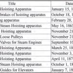
- Table-1

Get more of Elevator World. Sign up for our free e-newsletter.


