An Innovative Elevator System, Part Two
Feb 1, 2017

More on the first American depiction of a passenger elevator installation from cellar to penthouse.
This is the conclusion of a two-part article (which began in ELEVATOR WORLD, January 2017) that examines the first U.S. publication of a set of drawings that depict a passenger-elevator installation from basement to penthouse. The drawings first appeared in a pamphlet published by Otis Brothers in 1870: Description of Otis’ Patent Safety Passenger Elevator (Figure 1). Part one of this article examined the steam hoisting engine and associated safety brakes, the winding-drum stop limit safety, Elisha Otis’ original ratchet-and-pawl safety device, the guide rails and the car running gear. This article will conclude this investigation with an examination of Otis’ patented safety drum and automatic sheave brake, and the drawing’s publication history in the early 1870s.
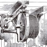
Otis’ safety drum was advertised as a critical component of its passenger and freight elevators throughout much of the 1860s and 1870s. Charles Otis patented the safety in February 1865 (“Improved Hoisting Apparatus,” U.S. Patent No. 46,580). The device employed a winding drum located at the top of the hoistway that carried the hoisting rope(s) (Figure 2). The drum was connected to a standard flyball governor, which was, in turn, connected to a brake on the safety drum. If the drum exceeded a preset speed, the action of the governor activated the brake. Otis’ 1869 catalog (Otis Brothers & Co.’s Patent Safety Hoisting Machinery Illustrated Descriptive Catalog and Price List) included an engraving of the safety drum (Figure 3) and a detailed description of its operation:
“It should be noticed that the cable between the car and the safety drum at the top, which we have uniformly called the lifting cable, is distinct from that which runs from the safety drum to the winding drum near the engine at the ground level, and both are made fast to the safety drum by their ends, the one winding on while the other winds off. An ordinary steam-engine governor is connected with this drum in such manner that its lift, whenever a certain moderate speed is exceeded, will trip a heavy weight attached to the long arm of a lever which operates a brake of ample force to stop the descent of the heaviest load. . . . This automatic brake is made of extra power and strength, far beyond its probable requirements, and in our passenger elevators, is doubled: that is, two brakes are attached, one at each end of the drum, acting independently, and either of them powerful enough to arrest the drum under all circumstances.”
This account, with its reference to two brakes “acting independently” prompts the question, “What activated the second brake?”
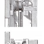
An examination of the drawings clearly reveals the safety drum (seen in elevation and plan view) (Figure 4). These drawings also depict another safety device: Otis’ automatic sheave brake or safety sheave, which was operated by the second brake referenced in the 1869 catalog. The operation of this safety was described in Otis’ 1870 pamphlet as follows:
“Thesheave S, around which one of the main lifting ropes passes inleading from the engine to the car, has its bearings in the slidingframe T, which is connected by means of the chain U to the weight on the brake lever V. So long as the weight of the car is supported by the rope, W, the sheave will be depressed, the brake lever raised and the brake kept free from the large friction wheel X. But, if by any means the weight of the car should be taken from this rope, the sheave would be drawn up by the gravity of the weight V and the brake R be immediately brought into action, stopping and securely holding the drum and effectually preventing any further motion so long as the rope remains slackened. . . . The rope V connects from one set of the safety fixtures in the car directly to the safety drum and is firmly secured to it. This rope is successively coiled onto and uncoiled from the safety drum, as the car ascends and descends, by the action of the car and the weight Z, the weight also acting as a partial counterpoise to the car.”
This feature was the last component of Otis’ 1870 elevator patent assigned to Charles R. Otis and Norton P. Otis: “Improvement in Hoisting Apparatus,” U.S. Patent No. 113,555 (April 11, 1871). However, its application — as illustrated in the drawings — resulted in a unique roping scheme.
A comparison of the basement and penthouse drawings clearly shows that the winding drum is placed perpendicular to the safety drum; therefore, it would be very difficult, if not impossible, for a cable to run from the winding drum to the safety drum. In fact, what might be termed the “power hoisting cable” ran from the winding drum, over the safety sheave and down to the car. A second hoisting cable connected the car to the counterweight via the safety drum. (The drawings appear to show a single cable wrapped around the safety drum.) This unusual roping scheme resembles other innovative 19th-century systems that were patented but never implemented. However, in this instance, at least one Otis elevator was built using this design. A detailed description of this elevator, installed in the Congress Hall Hotel in Saratoga Springs, New York, was included in Otis’ 1869 catalog.
The original Congress Hall Hotel burned in 1866, and it was rebuilt and reopened in 1869. Otis described the building’s elevator as “the only example of its grade to be seen in the Eastern States,” which may imply that it was the first elevator built that employed its new safety sheave. The hoistway was described as:
“. . . about 7 ft. square and 70 ft. high, extending through five stories, from the basement to the roof, and terminating in a cupola which encloses the suspensory machinery, safety drum, sheaves, etc. The weight of this machinery, instead of resting on the roof or framework of the building, is supported, in part by the brick partition which forms one side of the hoistway, and on the other three sides by the heavy upright timbers of the frame. Of these there are two corner posts, 8 in. square, and two guide posts, 9 in. square, all four extending from ground to roof and bolted into the framework of the building at all points. The safety ratchets, which are bolted upon the inner faces of the two guide posts, also stand upon the foundation, from which they extend, like iron pillars, to the roof. Their teeth are 2 in. wide, and their weight 16 lb. to the foot, and over 2,000 lb. in the aggregate.”
The basement hoisting engine was 6 ft. high and occupied “a space only 7 ft. square.” The car was supported by two 1.375-in.-diameter steel “lifting cables,” one of which wrapped around:
“. . . the safety drum at the roof. This cable alternates in the groove of the safety drum with another cable of the same size carrying the counterbalance weight, which runs in a recess in the wall, entirely out of sight and hearing. The other lifting cable passes over the patent safety sheave at the roof, and thence down, between the car and the hoist casing, to the windingdrum of the engine, from which it communicates power and motionto the car.”
The operation of the safety sheave and safety drum were described as follows:
“The journals of the safety sheave turn in boxes, whichrest ordinarily on a firm bed but are free to rise, in a pair of verticalguide frames, and are connected by an iron hanger to a pulley rope,which supports by its other end a 700-lb. weight on the long armof a brake lever belonging to the safety drum. The tension of thelifting cable on the sheave thus keeps this weight and lever uplifted;but, in case this tension is interrupted by the breaking or slackingof the lifting rope, the weight falls, lifting the sheave in its slidingboxes and bringing down the weight with tons of force upon thebrake, which instantly stops the drum and car. . . . There is another equally powerful brake lever and weight on the other end of the safety drum, which are thrown into action by any occurrence which may cause the machinery to run at an extraordinary speed. This is effected by means of an ordinary steam-engine governor, which throws out its balls when accelerated, and trips the brake-lever weight, instantly arresting the car.”
The 1869 catalog also included an equally detailed description of the elevator car:
“The car is a sumptuous compartment, about 7 ft. square and 11 ft. high, domed overhead, with skylights, ventilators and chandeliers supplied with gas through a flexible tube; below richly carpeted, with a large mirror and luxurious sofas around three sides. The sides and the domes overhead are finished throughout with panels, pilasters, brackets, carvings and moldings in richly variegated colors of bird’s-eye maple, French walnut, tulip wood and ebony, lighted up with chaste and appropriate touches of gilding.”
At first glance, it appears that the 1870 drawings illustrated the Congress Hall Hotel installation: they depict a hoistway serving five floors and a “sumptuous” car equipped with “luxurious sofas.” However, a closer inspection reveals an all-masonry hoistway enclosure (the hotel hoistway had only one masonry wall), the presence of a break line in the hoistway drawing that indicates a taller shaft, and the car sofa extends along only two sides. Thus, the drawings may have been intended to depict an ideal installation, represented by the all-masonry hoistway.
This unique set of drawings had a life beyond the appearance in Otis’ 1870 pamphlet. They accompanied an article published in the November 1870 issue of The Technologist, a magazine that described itself as “An Illustrated Journal of Engineering, Manufacturing and Building.” The article’s text was essentially a republication of the contents of Otis’ pamphlet. Whereas this article was simply titled “Improved Passenger Elevator,” when the drawings reappeared two years later in The American Builder (October 1872), they accompanied an article titled “The Modern Elevator.” Unlike its predecessor, this article was an original piece, which offered readers a broad introduction to Otis’ elevator.
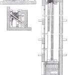
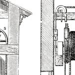
The drawings appeared for a third time in 1874 in the British publication Spons’ Dictionary of Engineering. They appeared in a section titled “Lifts, Hoists, and Elevators,” which illustrated a range of elevator systems (including other Otis machines). While the accompanying text was, again, a reprint of the 1870 pamphlet, the drawings were, apparently, redrawn for this publication (Figure 5). The “new” drawings are easier to read (compare the legibility of the counterweight as seen in Figures 1 and 5), and they contain an error. A close examination reveals that the British engraver added a rope to the top-right side of the winding drum, making it appear as if both hoisting ropes passed over the safety drum (Figure 6). This mistake may indicate that the engraver did not understand the operation of Otis’ elevator; thus, he was attempting to “correct” a perceived error in the original drawing.
Although it is impossible to calculate the impact of these drawings’ publication in the U.S. and Europe (and more instances of their republication may be awaiting discovery), it may be safe to assume that their relatively complete presentation of a modern passenger elevator played an important role in introducing and selling this technology to the world at large.
- Figure 1: The description of Otis’ Patent Safety Passenger Elevator (1870)
- Figure 2: “Safety Drum,” Charles R. Otis, “Improved Hoisting Apparatus,” U.S. Patent No. 46,580 (February 28, 1865)
- Figure 3: “Safety Drum,” Otis Brothers & Co.’s Patent Safety Hoisting Machinery Illustrated Descriptive Catalog and Price List (1869)
- Figure 4: “Safety Drum and Automatic Sheave Brake (Safety Sheave)”: description of Otis’ Patent Safety Passenger Elevator (1870)
- Figure 5: “Otis Brothers Safety Passenger Lift,” Spons’ Dictionary of Engineering (Division 6, 1874)
- Figure 6: “Safety Drum and Automatic Sheave Brake (Safety Sheave)”: (l-r) description of Otis’ Patent Safety Passenger Elevator (1870) and Spons’ Dictionary of Engineering (Division 6, 1874) (Red arrow indicates location of additional rope in 1874 drawing.)
Get more of Elevator World. Sign up for our free e-newsletter.


