An Instrument for Measuring the Distance between Guide Rails
Oct 1, 2012

A laser measuring instrument can help accurately measure the distance between guide rails.
by Yihui Ruan, Ning Li, Yuandong Jiang, Xueming Chen, Rongfeng Lu, Liang Ye, Zhe Cheng and Mingtao Chen
The distance between lift guide rails is an important parameter for characterizing the quality of a lift. The parameter has a direct impact on lift safety and ride comfort, as lift installation quality affects its normal operation to a large degree. Inspectors who measure the distance between lift guide rails with handheld tape measures risk poor measuring accuracy. This article introduces the principle, structure, composition and features of a laser measuring instrument that can accurately measure the distance between guide rails. The model is characterized by high response speed, low energy consumption and high reliability. The instrument is installed on top of the lift car by inspectors when the car is stationary on a certain floor. The inspectors can then evacuate the hoistway. When the lift runs its full travel at rated speed, the instrument can accurately measure the value of error in real time and save it.
Principle of Measurement
Figure 1 illustrates the hardware composition of this instrument. Two noncontact displacement sensors are installed on the edge of the car-top guardrail. One displacement sensor is in front of the working face of a car guide rail, which is on one side of the car. The other displacement sensor is on the opposite side. The distance between them can be adjusted according to the horizontal interval between the car-top guardrails. If the two sensors have been adjusted, the distance between their sensing surface will have a fixed value, back to back. This value (d0) can be accurately measured.
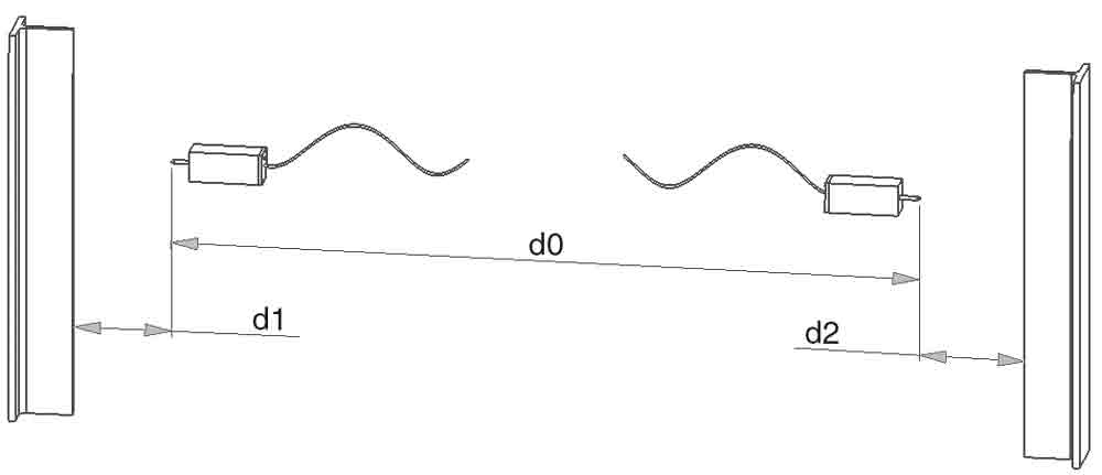
Figure 2 shows the measured distance of two car guide rails. Two sensors are at the same horizontal level. Additionally, two sensors and the car guide rails are in the same plane. The sensors can measure the distance (d1 and d2) between the sensors’ sensing surface and the working face of the car guide rail on both sides, respectively. If the tested lift runs at rated speed, the sum of the d1 and d2 will not be affected, even if the lift shakes slightly. The true value is D: D = d0 + d1 + d2. The design value is D0. The error of the distance between lift guide rails is ∆D: ∆D = D – D0 = d0 + d1 + d2 – D0.
Composition of Measurement
Figure 3 illustrates the hardware composition of the instrument. The system consists of displacement sensors, an analog/digital circuit, display screen and keys. The core of the hardware is the microcontroller, embedded to implement an intelligent control algorithm. The device relates to two displacement sensors that can generate analog signals according to the measured distance. The noncontact linear sensors have an analog output proportional to the damping target distance. These sensors utilize inductive technology, making them capable of sensing any metal target.
The distance between the sensor’s sensing surface and the working face of the car guide rail varies linearly with its output voltage or current. The algorithm is implemented by using software. The analog/digital conversion circuit is used to generate signals the microcontroller can receive. A key processing circuit can transmit the operator instruction to the microcontroller. The chromatic LCD screen can display the error value in real time. The instrument makes the operation more convenient with a friendly human/machine interface.

Figure 2: The distance between two car guide rails 
Figure 3: Hardware composition of the device
Get more of Elevator World. Sign up for our free e-newsletter.


