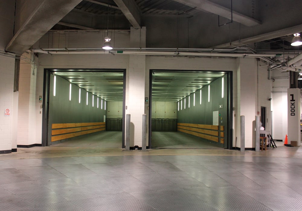
Design, installation of large vehicle lifting system called for creative thinking.
The Barclays Center has two 80,000-lb.-capacity side-by-side freight elevators engineered and manufactured by MEI Total Elevator Solutions, which conducted design, manufacturing and internal project management for the multipurpose indoor arena at its Mankato, Minnesota, facility. It also supported Otis during the installation of the elevators and trained Otis staff on the equipment. The team had confidence in installing the specialized units for the Brooklyn, New York, arena due to its prior experience with two other 80,000-lb.-capacity elevators at the City Creek Center project in Salt Lake City.
The constraints of the site, coupled with an event level designed below street level, forced project officials to develop a creative way to unload large semi-trucks hauling equipment for multiple types of shows and sporting events. Two freight elevators and a turntable were designed and installed at Barclays Center to make the most use of the facility’s tight space. They enable semi-truck or bus drivers to drive straight into either elevator from the intersection of Atlantic and Flatbush avenues on the southeast side of the arena. Once in the elevator, the truck or bus will be lowered to the court and locker room level, which is 34 ft. below street level. This level is also where the loading docks are located.
Exiting the elevator, the vehicle then pulls forward onto a massive turntable that rotates to allow backing up to the loading dock. Once unloading or loading of the truck or bus is completed, the vehicle is rotated again so it can move back onto the elevator. Vehicles are then transported via the elevator back up to ground level, where they can be driven directly onto the street. The elevators and the turntable were necessary due to the very narrow streets and tight access, which does not allow much space in which to move these large tractor-trailers and buses. The elevators and turntable not only made this possible, but also provided a safer solution for both pedestrians and drivers.
It took a total of 14 semi-trucks to ship the two complete elevators from MEI’s headquarters in Mankato to the site location. Once on site, Otis’ team worked around the clock for six weeks to meet a tight completion date in September 2012. The MEI team conducted vigorous design and engineering work. It also presented elevator data and building structure requirements at regular meetings, and hosted in-house visits. All these aspects played an important role in the elevator installation, which was considered a great success. MEI’s engineering team used software-analysis programs to calculate the best, most accurate results and correct measurements. All engineering calculations were first done manually, then in visual-analysis software programs to verify that all load reactions and deflections were acceptable.
Elevators
After being contacted by Otis to design and manufacture the freight elevators, MEI submitted a 98-page analysis of the engineering calculations for them. This analysis included Kx side-to-side turning moment and manual frame member calculations, 2D Frame/Truss and Visual Analysis software, manual calculations following a Visual Analysis model, and ANSYS models. Within the Kx side-to-side turning moment, there were calculations for weak axis stile, Fx rail force, stile-to-bolster/crosshead-bolt connections, and crosshead and bolster Kx resistance.
Manual frame member calculations included bolster and platform beam, platform stringer and jack beam calculations. The 2D Frame/Truss and Visual Analysis software included frame design and member sizes; an example of model and loading nodes; and 12 load cases, such as loading diagram, load breakdowns, loads applied to model, maximum stress results and maximum deflection results. This also included maximum stress and deflection summaries for 12 load cases, maximum axial forces to be used for later manual and ANSYS analysis and rail force outputs for 12 load cases. Another portion included within this analysis consisted of manual calculations following the Visual Analysis model for the truss end and pin calculations and inner truss compression/truss calculations. The ANSYS models had jack beam/stile, platform support/truss and stile/truss connections. Other calculations, such as oil compression of car buffer/impact reactions, were also included.
The determinations of the side-to-side turning moment of the elevator were to be carried by each set of stiles. Since this beam is loaded in a mo re complicated manner, ANSYS software was also used to analyze stresses and deflections. (ANSYS analysis is critical to welded structures and connections to ensure stresses and deflections are kept at appropriate levels.) Each elevator has six stiles, six crossheads and six bolsters. A 2D frame was created in IES Visual Analysis software to look at all member stresses and deflections. Along with truck loading, the analysis includes the self-weight of the elevator platform, frame and cab. This analysis provided maximum axial forces to use for later calculations of truss ends and pine, buckling calculations and forces to apply in the finite-element-analysis models. This provided rail-guide loading forces for each load case scenario. The frame’s modeling in Visual Analysis was performed to analyze the platform frame/truss system. This software allows all specific member sizes and properties to be tested.
MEI also submitted a 24-page manual detailing of sling and platform installation. This was a description of specific installation procedures to follow for components and parts during installation. There were illustrations provided of what each part looked like and detailed captions for each. The manual was clearly written in an effort to ensure the proper installation of each part. It was used for guidance from the design and engineering phase through the end of project execution. Simple computer datalink connections (rather than old-fashioned parallel wiring) made the installation process more efficient.
The turntable then rotates so the trucks can back straight into the tight loading berths. There are four loading berths, and there is space for six to eight trucks. After unloading, the trucks drive back onto the turntable and are rotated so they can drive straight back onto the elevator. Once on the elevator they are brought back up to street level and can exit directly onto the street safely.
Get more of Elevator World. Sign up for our free e-newsletter.


