Basics of Testing And Certification of Safety Components
May 15, 2023

(Door Locking Gear and Safety Gear)
Lift safety components are identified in Annex III of the Lifts Directive (2014/33/EU). Safety components in lifts include landing (car) door locking gears, gears that prevent overspeeding of the lift car, gears that restrict overspeeding, buffers, safety gear that are connected to hydraulic power circuits and prevent falling and electric safety gears with electronic components. These components should be tested and certified according to the methods specified in the annexes of the Lifts Directive, and the EN 81-50 standard determines how to make the testing and certification.
In this article, I will try to explain the basic requirements for the certification of safety components in light of the EN 81-50 standard.
Testing and certification stages of landing and car door locks are explained in detail in Section 5.2. of the EN 81-50 standard. In the first stage, the applicant should submit the technical file of the product to the certification body for review and approval. The technical file should contain detailed drawings of the locking gear and electric safety gear, drawings of the door at minimum and maximum dimensions, details of materials used, strength calculations for the locking gear, electrical circuit diagram, diagram of electronic card (if any), software files (if any), installation and maintenance guides, sample product for testing, a copy of declaration of conformity and a copy of the product label.
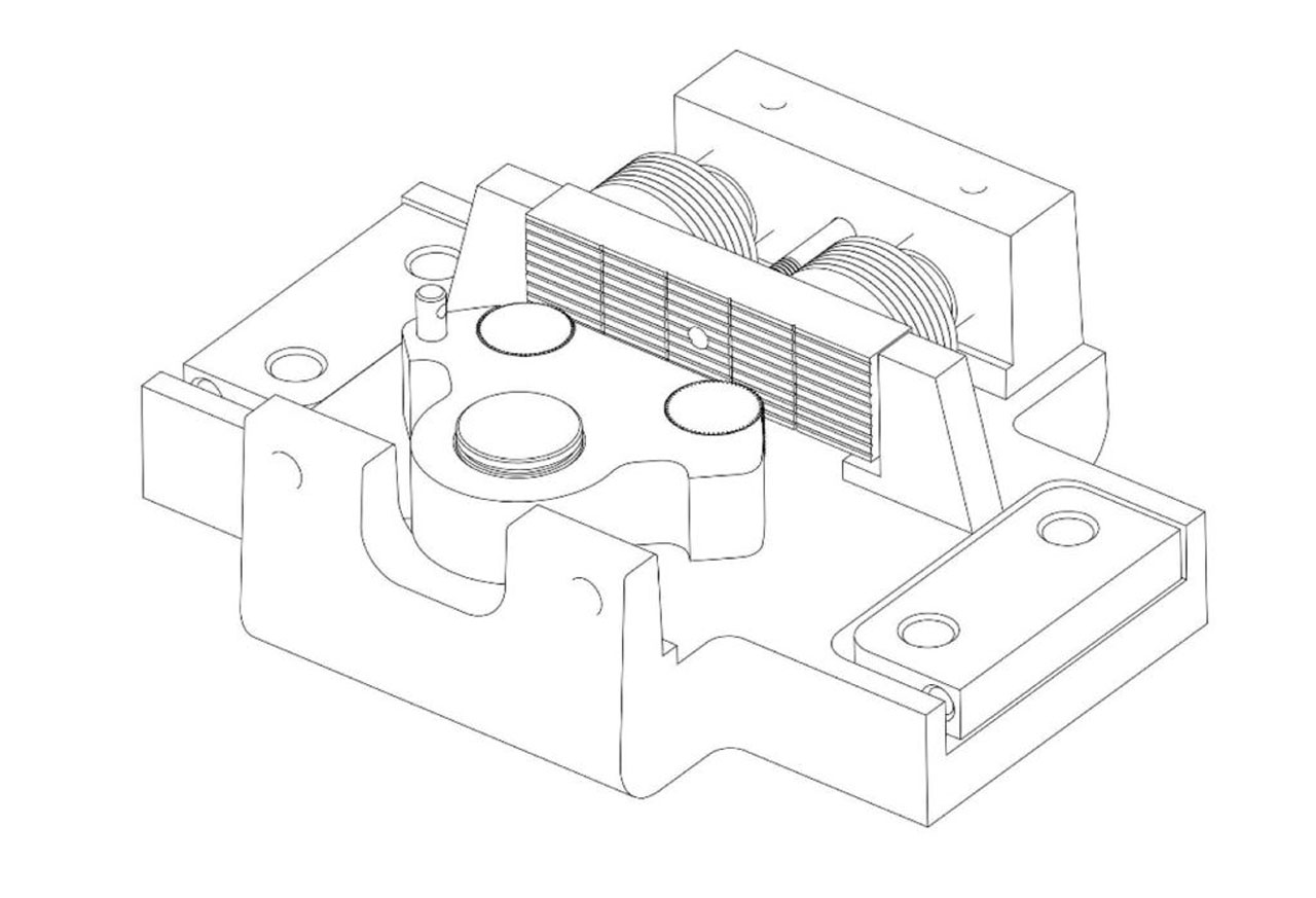
Lock Drawing
After full review of the technical file is completed, various mechanical tests and experiments will be conducted on the product. Mechanical tests are endurance tests, static tests and dynamic tests, respectively. In the endurance test, the door lock should be turned 1,000,000 full cycles. One cycle is the full movement of the door lock in the locking and unlocking direction. In the endurance test, the electric safety gear should also be locked and unlocked by being exposed to a current twice the rated current at the rated voltage. A resistor should also be serially connected to the electrical circuit. In the endurance test, the locking gear and safety gear should turn 60 cycles (+/-10%) in one minute.
In the static test, a force of 3000 N for hinged/manual doors and 1000 N for automatic doors should be applied incrementally for 300 s in the unlocking direction, at the point closest to the area where a person would apply force to unlock. In the dynamic test, a mass of 4 kg should be dropped from a height of 0.5 m in the unlocking direction, and its impact should be examined. At the end of mechanical tests, there should not be any abrasions, deformations or breakages that may negatively affect the safety of the door lock.
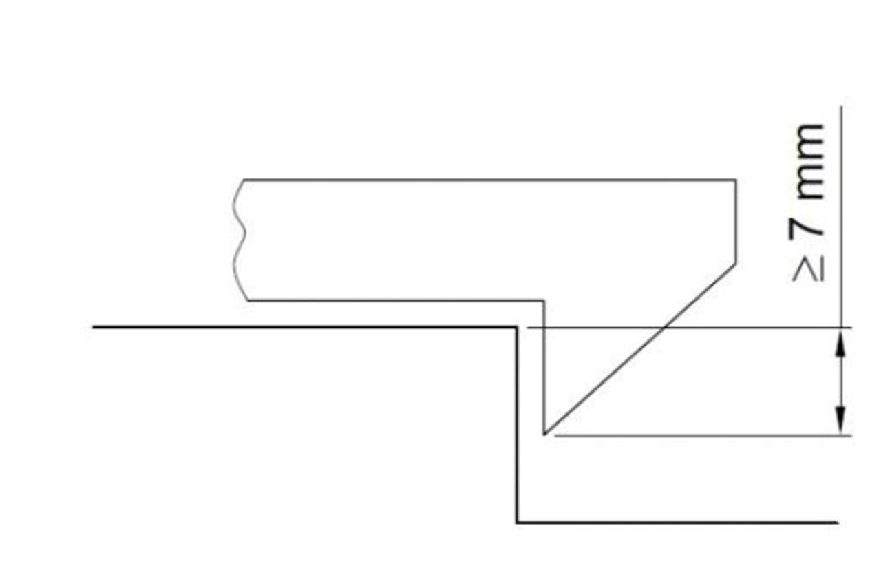
A series of electrical tests should also be applied on the lock safety gear of the landing and car doors of the lift. First, at least 7 mm mechanical locking should be performed when the safety circuit is activated. The current and voltage to be applied in the circuit-breaking ability test vary, depending on whether the electric safety gear has direct or alternating current switch. In the circuit-breaking test, an inductance and a resistor should be serially connected to the electrical circuit. During the test, the lock and switch should be locked and unlocked at intervals of 5-10 s and at normal speed, and the switch should be at least .5 s. This locking and unlocking process should be performed 20 times for direct current switches and 50 times for alternating current switches. One hundred and ten percent of the rated voltage for both current switches should be applied, with a current 11 times the rated current for alternating current switches, and a current corresponding to 110% of the rated current for direct current switches. In the residual current resistance test, which is another electrical test, an alternating current of 175 V and 50 Hz is applied to electrical safety switches. Later, clearance and creepage distances vary between 3 and 4 mm, depending on the IP protection level of the switch.
In the case of doors with multiple panels, gears connecting the panels are considered as parts of the door lock, and should be subject to the same mechanical tests with the lock. In addition to all these tests, the presence of gears that prevent the panels from falling when the pulleys in the mechanism are broken or damaged, or of gears that prevent the carriers from being separated when the connection elements between panel carriers are disconnected should be checked.
Testing and certification of the safety gear are also explained in Section 5.3. of the EN 81-50 standard. First of all, the applicant should submit the following information and data to the certification body: environmental conditions for using the product, useful life of the product, aging and rejecting criteria, installation and maintenance guides, drawings of the safety gear and clutch surfaces, calculations, minimum and maximum masses (P+Q), maximum rated speed and maximum activation speed, information and features of springs used, types and dimensions of rails that the safety gear can be used, surfaces, features and details of materials used, a copy of declaration of conformity, a copy of product label and sample products. Before starting product tests and controls, the information and data submitted should be reviewed and approved by the certification body. As a matter of course, the tests and controls should not be started without completing this stage.
After the review and approval of the technical file is completed, a series of controls and tests should be performed, depending on the type of the safety gear. If the brake to be tested is emergency braking type, the guide rail is moved through the brake gear by means of a workbench or mechanism that does not change the speed. In the meantime, the distance covered is recorded in a diagram as a function of force. After the test, the thickness of the body and clutch elements should be measured and compared with the rated values. Moreover, another diagram observing deformation should also be prepared. Maximum permissible mass in emergency braking type safety gear is calculated as follows:
– If the elastic limit is not exceeded:
(P+Q)1: Permissible mass,
K: Integral of the area falling below the force-distance graph,
gn: Gravitational acceleration,
h: Free fall distance.
The free fall distance is calculated as follows:
Here, V1 is the activation speed of the overspeed regulator.
If the elastic limit is exceeded, two calculations are made, and the greater mass can be selected.
Here K1 is the integral of the area up to the value reaching the elastic limit.
K2 is the integral of the area up to the value corresponding to the maximum force.
Brake Drawing
If the brake to be tested is sliding type, the owner of the product should provide information on the mass(es) to run the test, activation speed of the regulator and the mass to be hung. The test should be performed as free falling. This is an important subject. During the test, the total free fall distance and braking distance in guide rails, sliding distance of speed regulator rope or similar mechanism and total movement distance of springs should be measured and found out as a function of time directly, indirectly or through calculations. Moreover, the average braking force as well as instant minimum and maximum braking forces should also be determined. If the sliding safety gear is certified for one mass only ((P+Q)1), 4 tests should be performed with the (P+Q)1 mass that the manufacturer has found out by dividing the braking force by 16 — as anticipated to achieve the deceleration value of 0.6 gn — waiting for the clutch elements to return to their normal temperature after each test. Each test should be performed in an unused section of the guide rail. The braking force of the sliding brake gear to be certified for a single mass is the average of the braking forces found out in the four tests performed. The difference between the determined average braking force and the rated braking force for average deceleration value of 0.6 gn should not be more than +/-25%.
If the sliding safety gear is tested for different masses, the manufacturer should provide a diagram or formulation showing the change of braking force according to the adjustment parameter. I recommend that tests are performed for intermediate values in addition to the minimum and maximum masses given. Four tests should be performed for each grade, and the average of braking forces found out in the tests should be accepted as the final braking force. The difference between the measured braking force and the rated braking force should not be more than +/-25%.
Permissible mass (P+Q)1 for gradually adjusted braking gear and for a single mass should be calculated as follows:
In the formula, FB is the braking force calculated as explained above.
Permissible mass (P+Q) or mass values according to adjustment parameter — in the case of gradually sliding brakes — should be written in the certificates of brake gears.
I hope my article could be useful for my readers. I wish you safe days.

Get more of Elevator World. Sign up for our free e-newsletter.
![]()


![]()