Breakthrough in Safe and Cost-Effective Elevator Hoistway Control
Sep 1, 2016
Together, APS and iDiscovery provide an array of benefits.
This paper was presented at  Madrid 2016, the International Congress on Vertical Transportation Technologies, and first published in IAEE book Elevator Technology 21, edited by A. Lustig. It is a reprint with permission from the International Association of Elevator Engineers
  (website: www.elevcon.com).
The century-old elevator hoistway safety control system has had its day. More and more safety-related functions are necessary to maintain the level of safety, while more features for convenience, maintenance and pre-maintenance are additionally installed. The contactless, very robust and precise absolute positioning system (APS), in combination with the position supervisor unit (iDiscovery), takes over all safety-relevant functions in the hoistway and triggers a motor brake via the safety chain, or directly using the electric safety gear.
Detection of overspeed or unintended car movement, as well as pre-opening of doors, leveling and releveling with open doors, and retardation control are covered by iDiscovery. Virtual limit switches, virtual inspection limit switches and virtual shelter spaces are all covered by iDiscovery. APS and iDiscovery, in combination, significantly reduce the cost and complexity of elevator equipment, as well as installation time.
Introduction
What is going on in different technology branches? In terms of automation technology, a new era has begun. It is called “Industry 4.0.” Sensors are getting more intelligent and can calibrate themselves and trigger events in case of abnormalities. Control systems are getting more features for pre-maintenance to supervise themselves or increase efficiency.
Looking at the automobile industry, trucks are using steer-by-wire technology, changing from hydraulic to electric systems. Cars learn to communicate with other cars to help prevent collisions and avoid traffic jams. By comparison, looking at the elevator industry might suggest it is a big, old dinosaur using contactor technology and electric circuits to fulfill codes and standards. There is, of course, a reason for that. The past has proved that this technology is reliable and safe. Therefore, a change to new technology, which has yet to be proven by the market, needs to be as reliable as the technology currently in use, and needs to be as simple for installation and maintenance that technicians can handle it with the same precision and care as they can the proven technology.
The task of an elevator is very simple. It has to vertically transport a person safely, quickly and without any interruptions, and it needs to be available 24/7. Furthermore, if unexpected events like power breakdown or loss of traction occur, an elevator must take care that no unsafe situation for the passenger can result.
The proposal is to use an APS in combination with iDiscovery to separate the safety-related functionality and the travel-related functionality. This means that a safety control supervises the hoistway in a safe manner to stop the elevator should any unsafe condition arise, and generate status information for the elevator control to allow easy and more efficient maintenance, pre-maintenance and comfort travel.
Functionality of iDiscovery
If intelligent sensors are introduced, the cost increases if no other tradeoffs are possible. A mechanical contact is still one of the safest and most cost-efficient solutions for reading back information of, for example, a door contact.
There must be other tradeoffs, which allow a reduction in cost and complexity:
- Door circuit (car and shaft door)
- Speed governor (tensioning device, speed governor, rope and safety gear)
- Retardation control (standard buffers are replaced by reduced buffers, safety switches and a travel pattern control device)
- Inspection (recall panel, inspection control pit and car, and mechanical installations to protect the technician)
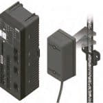
The above-mentioned hardware needs to be replaced by electronic means to gain a greater system benefit. Figure 1 shows iDiscovery in combination with the APS. APS produces contactless Safety Integrity Level 3-rated position and velocity information from the code tape, which is mounted in the elevator shaft. This information is transmitted to iDiscovery, which processes the position and velocity information together with the other shaft information to ensure a safe shaft environment for the passengers, as well as the technicians.
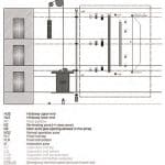
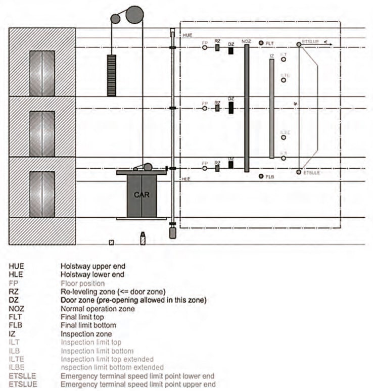
What is meant by shaft information? Figure 2 shows the elevator car together with three shaft doors and the “virtual” inspection and extended inspection limits. In the gray-dotted box, the virtual limit switches are shown, the positions of which are stored in the iDiscovery by safe means and are always monitored. The functionality is briefly explained immediately below the figure, and, more precisely, in the following sections.
Door Circuit
The most cost-effective solution for monitoring the door status is a mechanical contact. There is no other solution available on the market yet, which comes within the cost range of a pure mechanical contact. In the case of an express elevator with a long travel distance and few floors to service, or an elevator system with two cars in one shaft, where two virtual door circuits are needed, or such a system requiring more than two virtual door circuits, the complexity can be reduced if intelligent hoistway and car door contacts are used. The reduction of electric complexity means also that system reliability is increased, which leads to a cost benefit due to reduced maintenance.
EN 81-20:5.12.1.4 describes automatic bridging in the case of pre-opening doors. The iDiscovery bridges a shaft door automatically within the door zone if it is commanded to do so by the elevator control and if the speed limit and position of the car are within the given boundaries.
EN 81-20:5.12.1.8 and 81-2:5.12.1.9 require that bridging of the car and shaft doors is allowed in inspection mode to avoid the use of bridging cables, which can be easily forgotten in an elevator system and lead to an unsafe situation. The iDiscovery has separate door circuits for the shaft and car doors. If the car is operated in normal mode, each car door and shaft door movement is supervised by iDiscovery, which ensures the shaft and car-door safety chains operate as they should. Any unauthorized bridging of a shaft or car door will be detected during normal operation.
Pre-opening of doors and releveling of the car are supervised in each door zone to ensure:
- Bridging commanded by the control and car is within the right door zone
- The speed is within pre-opening or releveling limits
- No unintended car movement can occur (in accordance with EN 81-20:6.3.13)
The customer can choose if this is combined with an A3-certified motor brake, with an electronic safety gear (eSafety) or with the electric pre-trigger signal of a standard speed governor. The iDiscovery guarantees a deterministic reaction time, which can be used for the unintended-car-movement (UCM) calculation.
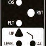
Figure 3 shows the door operation indicators together with the system operation indicators of the iDiscovery:
- ERR: This means that a system error has occurred, which may be reset by switching the iDiscovery off and on again.
- APS: If lit or flashing, there is no communication with the APS or the APS is not mounted accordingly and, therefore, no absolute position is available.
- OS: Overspeed has been detected.
- RC: Retardation control has occurred.
- UCM: UCM has occurred.
- RST: Reset button to switch back to normal operation.
- FLT: Final limit top has been reached.
- DZ, UP, LEVEL, DOWN: Indicates firstly if the car is in the door zone (DZ), if it is leveled (Level) or if it is above (Up) or below (Down) the door zone
- DZ: Door zone over-bridging activated.
- FLB: Final limit bottom reached.
The status information can also be read via proprietary CAN or CANopen (DS417) by the elevator control.
Retardation Control
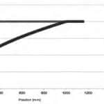
At the upper and lower ends of the elevator shaft, the iDiscovery always checks if the travel speed and deceleration are below the maximum allowed. If this is not the case, firstly, the safety chain is opened to brake using the motor brake, and, secondly, the safety gear is triggered. This functionality is also used in accordance with reduced buffer stroke (EN 81-20:5.12.1.3). The maximum possible speed limit curves are shown in Figure 4. If the car, for some reason, is accelerated to reach these limits, the safety chain is first opened (black curve), and the safety gear is then triggered (gray curve) to avoid the car hitting the buffer with more kinetic energy than allowed.
Speed Governor
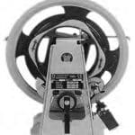
The conventional speed governor, as shown in Figure 5, has proven its reliability over many years. With old elevator installations, the requirements of the overspeed governor are to stop at a predefined overspeed and activate the safety gear by means of a rope. With today’s installations, it is useful to have an adapted stopping speed for UCM. If the speed within a door zone exceeds 0.8 mps or the end of a door zone is approached too quickly, the safety gear is triggered if, in leveling or releveling mode, the supervised speed can be lowered to 0.3 mps. If a maximum acceleration occurs when leveling with open doors, the UCM can be detected even earlier. If inspection mode is switched on and the elevator is commanded into the inspection shelter spaces (if the elevator travels over the inspection or extended inspection limits), the safety chain is first opened to activate an A3-certified motor brake. If the car travels 50 mm beyond this limit, the safety gear is activated to protect the technician from collision. A conventional speed governor cannot handle the described modes accordingly, because it is built for one (or, maximum, two) different speeds without any position information. These functions can be substituted if the conventional speed governor is replaced by an APS and iDiscovery. In this case, the level of safety increases dramatically. The iDiscovery can trigger a conventional speed governor by using the pre-trigger signal of the speed governor or by directly triggering any electronic safety gear.
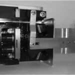
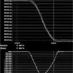
Figure 6 shows the Cobianchi PC24GO electronic safety gear. The diagram in Figure 7 shows the triggering of the safety gear. The top diagram shows position over time, while the second shows speed over time.
The safety gear is triggered by iDiscovery at 2 mps. The overall reaction time is about 117 ms. The iDiscovery has been configured to 50 ms of reaction time. The reaction time needs to be chosen very carefully. If it is too short, robustness is lost, and the safety gear may be activated unexpectedly. If the reaction time has been set at over 100 mps, the system itself may be very robust against unexpected activation. However, the time where the car is still being accelerated becomes too long for adequate system behavior. Tests showed that the trigger time should be between 50 ms and 100 ms. The maximum speed, in this case with an activation speed of 2.0 mps, is 3.15 mps.
Inspection
The EN 81-20:5.12.1.5 and 81-20:5.12.1.6 standards feature a big change in the function of recall panels and inspection controls. If recall panels and inspection controls are connected to iDiscovery, it prioritizes the use of recall and inspection in accordance with the standard. Independent of the inspection panel (car or pit) and access-door switches (headroom or pit), iDiscovery switches on the virtual inspection limits and extended inspection limits to ensure enough shelter clearance and prevent unsafe situations for the service technician. The signaling of the inspection module is shown in Figure 7. The signaling is:
- RP: Recall panel switched on.
- CIC: Car inspection control switched on.
- PIC: Pit inspection control switched on.
- ST: Headroom-access door top has been opened.
- SB: Pit-access door bottom has been opened.
- ILT: Inspection limit top activated.
- ILB: Inspection limit bottom activated.
- ILTE: Inspection limit top extended activated.
- ILBE: Inspection limit bottom extended activated.
Even if the car has broken one of the virtual limits, and the iDiscovery is reset, it prevents the car from being moved further in the wrong direction by keeping the safety chain open, even in the event of a reset. Clear visualization helps the technician easily understand which part of the safety chain may be causing the trouble, without the need for bridge safety chain contacts. This simplifies troubleshooting and avoids unsafe situations.
Results
The iDiscovery has been developed on a modular basis. Several test installations show that modularity is key. Elevator installations can be set up by using the door circuit module, the electronic safety gear module or the inspection module individually or all together.
All safety-relevant information is processed within the iDiscovery. Therefore, the elevator control itself can concentrate on software with Industry 4.0 functionality, algorithms and customer features. There is a clear separation of safety-relevant data processing and non-safety-relevant data processing.
With its modularity, the iDiscovery system can also be used for high-rise installations in combination with a door safety chain with intelligent door contacts. The overall safety functionality stays the same and makes it simple for the technician to install and maintain an iDiscovery. The author regards this as key to making a system safe, and means having a clear and simple system and installation process. This applies to each elevator installation, whether it is low-rise or high-rise.
- Figure 1: iDiscovery and APS
- Figure 2: Overview of the virtual switches in an elevator shaft
- Figure 3: Door operation indicators
- Figure 4: Maximum travel curve for retardation contro
- Figure 5: Conventional speed governor (Source: Internet Wikipedia)
- Figure 6: Cobianchi PC24GO electric activated safety gear
- Figure 7: Example of an electronic safety gear triggered by the iDiscovery at 2 mps (Source: Cobianchi)
- Figure 8: Inspection operation of the iDiscovery
Get more of Elevator World. Sign up for our free e-newsletter.
