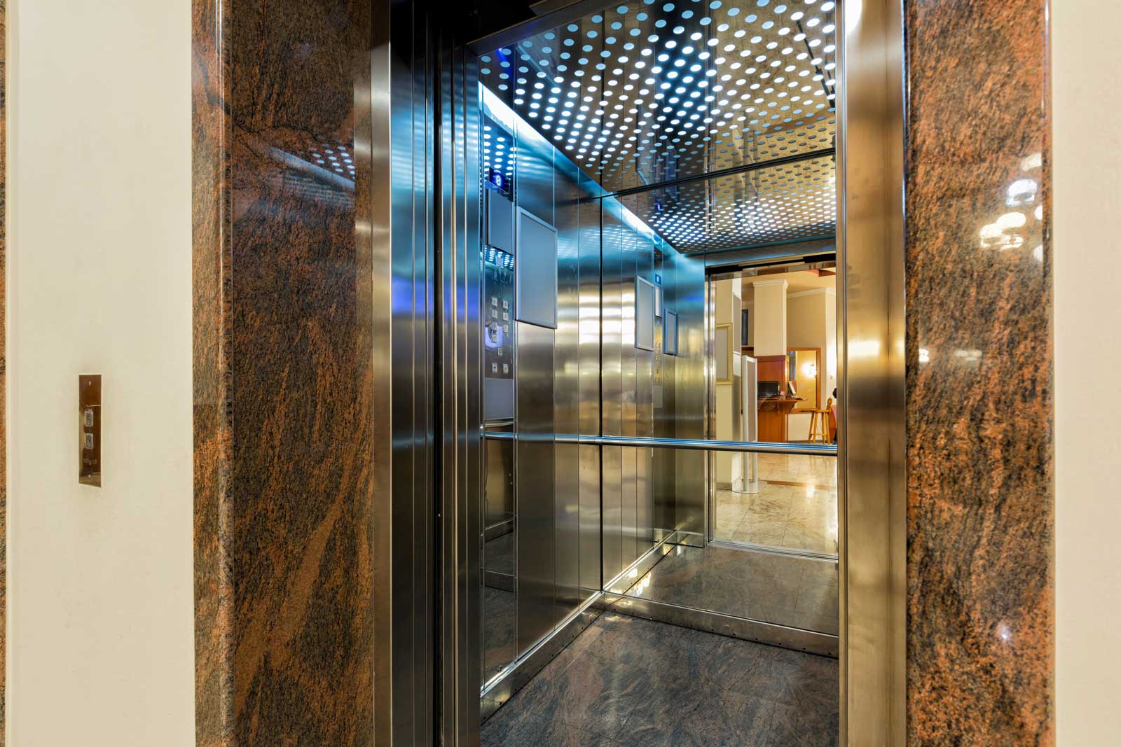
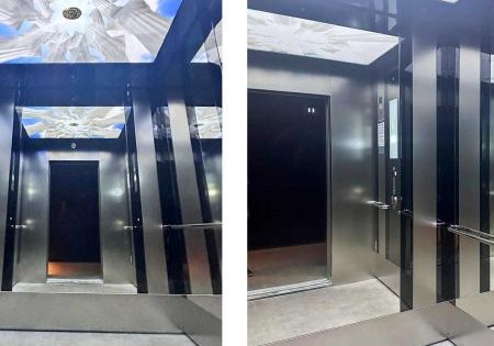
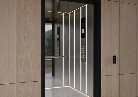
Cars are components ensuring safe transportation of people and/or loads. Lift car designs are shaped according to needs, places of installation, standard requirements and aesthetic expectations. As in all designs, there are some basic requirements and principles that should be taken into consideration while designing cars. These requirements are of critical importance to come up with a successful design both aesthetically and functionally. In general, the basic requirements of a car design are as follows:
- Aesthetics (decoration, design)
- Materials (visual quality, strength, hygiene, easy cleaning, etc.)
- Accessibility (dimensions, controls, additional components)
- Comfort (insulation for vibration and noise, lighting, ventilation)
- Technical (capacity, controls)
- Energy Efficiency (LED lighting)
- Regulations and Standards (local regulations and national/international standards)
Summary of car requirements under lift standards in force:
Dimensions:
- Net inside height of the car should be at least 2.0 m.
- Car area should be in minimum and maximum ranges defined in the standard.
- There should be limited car area to prevent overloading.
Car walls:
- The car should be completely surrounded with walls, floor and roof except for permitted openings.
- When a force of 300 N is distributed equally on a 5 cm2 area with circular or rectangular cross section at a right angle to the wall at any point from the inside to the outside of the car, it should show resistance without causing the following:
- Any permanent deformation above 1 mm
- Any elastic deformation above 15 mm
- When a force of 1000 N is distributed equally on a 100 cm² circular or rectangular area at a right angle at any point from the inside to the outside of the car, it should not cause permanent deformation above 1 mm.
- Glass or partial glass car walls should be made up of laminated glass according to ISO12543-3:2021. Laminated glass should have the minimum thickness and properties specified in the standard (EN 81-20/EN 8100-1).
| Glass Type | Incircle diameter | |
| Max. 1 m | Max. 2 m | |
| Maximum thickness (mm) | Minimum thickness (mm) | |
| Hardened laminated or tempered laminated | 8 (4+4+0,76) | 10 (5+5+0,76) |
| Laminated | 10 (5+5+0,76) | 12 (6+6+0,76) |
Car door, floor, walls, ceiling and decorative materials:
- Load-bearing structures of the car should meet the requirements of EN 13501-1:2018, class A or B:
- Floor : Cfl – s2
- Walls/Door : C -s2, d1;
- Ceiling : C -s2, d0
- Considering the lift environment, there should be non-slip floors in places where the passengers are generally expected to enter the car with wet shoes. The same materials used in lift lobbies are recommended for the floors of lift cars.
- In vandal-resistant lift cars (EN 81-71 Category 2):
- Materials to be used for ceiling and wall surfaces should be fireproof according to EN 13501-1 Class A2, while materials to be used for car floors should be fireproof according to EN 13501-1 Sınıf A2fl.
- Materials to be used for walls should be cutproof against the objects specified in the standard.
- All handrails should be able to bear a force of 2,500 N applied in any direction at the most inconvenient point.
- If there are any mirrors, they should be built-in without any protrusions, and glass mirrors should be laminated.
- Resistance to corrosion arising from body fluids and cleaning solvents should be taken into consideration in the selection of car surfaces.
- Materials to be used for ceiling and wall surfaces should be fireproof according to EN 13501-1 Class A2, while materials to be used for car floors should be fireproof according to EN 13501-1 Sınıf A2fl.
Lift skirt (skirt sheet):
- As defined in the standard, there should be a skirt with a vertical length of 0.75 m on each door threshold, at least to the full width of the open stop entrance it corresponds to.
- When a force of 300 N is distributed equally on a 5 cm2 area with circular or rectangular cross section at a right angle to the landing side at any point along the lower edge of the vertical part of the skirt, it should not cause:
- Any elastic deformation above 1 mm
- Any elastic deformation above 35 mm
Emergency doors:
- If an emergency door is mounted on the car ceiling, minimum opening dimensions of this door should be 0.40 m × 0.50 m (space permitting, a door of 0.50 m × 0.70 m is preferable).
Car ceiling:
- Car ceiling should have the mechanical strength to support the specified number of persons for shelter spaces.
- Car ceiling should be able to bear a minimum force of 2,000 N applied at any point on an area of 0.30 m x 0.30 m without any permanent deformation.
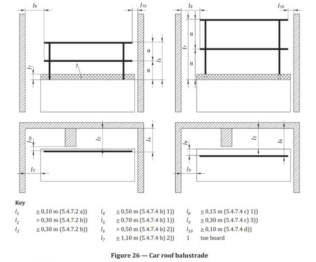
- There should be a foot guard with a height of 0.1 m on the outer edge of ceiling or of guardrail.
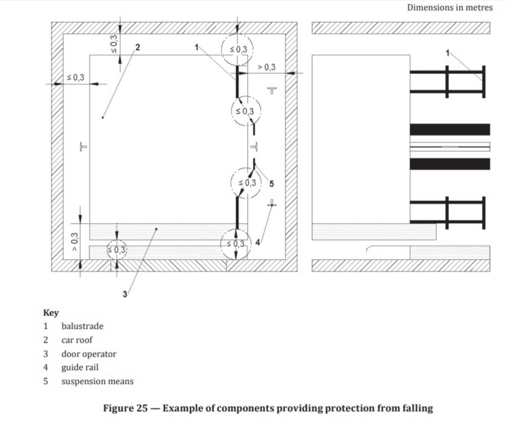
- There should be a guardrail if the clearance beyond the outer edge of car ceiling and on the horizontal plane at a right angle to the wall of the well exceeds 0.30 m. The guardrail consists of a handle and a space bar at half height.
- The guardrail’s height should be 0.70 m if the clearance in the inner edge of the guardrail and on the horizontal plane is up to 0.50 m, and it should be 1.10 m if the clearance exceeds 0.50 m. The guardrail can be located at a maximum horizontal distance of 0.15 m from the parallel edge of the car, or at a horizontal distance with a deflector from the edge of the car to the guardrail in order to protect the people standing there. The horizontal distance between the ends of the guardrail and the wall of the well or the components in the well should not exceed 0.30 m.
- The horizontal distance between the outer edge of the guardrail and any component or wall should be 0.10 m.
- When a force of 1,000 N is applied horizontally at a right angle at any point in the upper part of the guardrail, it should show resistance without any elastic deformation above 50 mm.
- In vandal-resistant lift cars (EN 81-71), ceilings should be able to bear a mass of 150 kg at any point that people can hold and hang for Category-1, and should be designed in a way that people cannot hold and hang at any point for Category-2.
Ventilation:
- There should be ventilation holes in the upper and lower parts of cars. No flat and round bars with a diameter of 10 mm should pass through these holes (In vandal-resistant lift cars, they should de designed in a way that flat bars with any cross sections cannot pass through).
- The effective area of ventilation holes located in the upper part of the car should be at least 1% of the existing car area. The same is applicable for ventilation holes located in the lower part of the car. No more than 50% of the required area should be taken into account in the calculation of the area of ventilation holes, considering the openings around car doors.
Lighting:
- The car should be equipped with electric lighting (minimum light intensity of 100 lx), which is mounted permanently. The lighting should consist of at least two different light sources connected in parallel.
- In case of power outages, there should be chargeable and automatic emergency lighting equipment that can provide minimum light intensity of 5 lx for 1 h in the car.
- In vandal-resistant lift cars (EN 81-71), lift car lighting connections should be built-in without any protrusions in a way that they cannot be seen and unauthorized access is prevented.
Accessibility:
- Car door entrances should be automatic sliding doors and have a minimum net width of 900 mm (800 mm for existing buildings where Type-1 cars can be used).
- Car dimensions:
- Type-1: 1000 x 1300 mm / 450 kg (in existing buildings where Type-2 cannot be installed)
(1 wheelchair user) - Type-2: 1100 x 1400 mm / 630 kg
(1 wheelchair user + 1 companion) - Type-3: 1100 x 2100 mm / 1000 kg
(1 wheelchair user + other passengers / suitable for stretcher use) - Type-4: 1600 x 1400 / 1400×1600 mm / 1000 kg
(1 wheelchair user + other passengers) - Type-5: 2000 x 1400 / 1400×2000 mm / 1275 kg
(1 wheelchair user + other passengers)
- Type-1: 1000 x 1300 mm / 450 kg (in existing buildings where Type-2 cannot be installed)
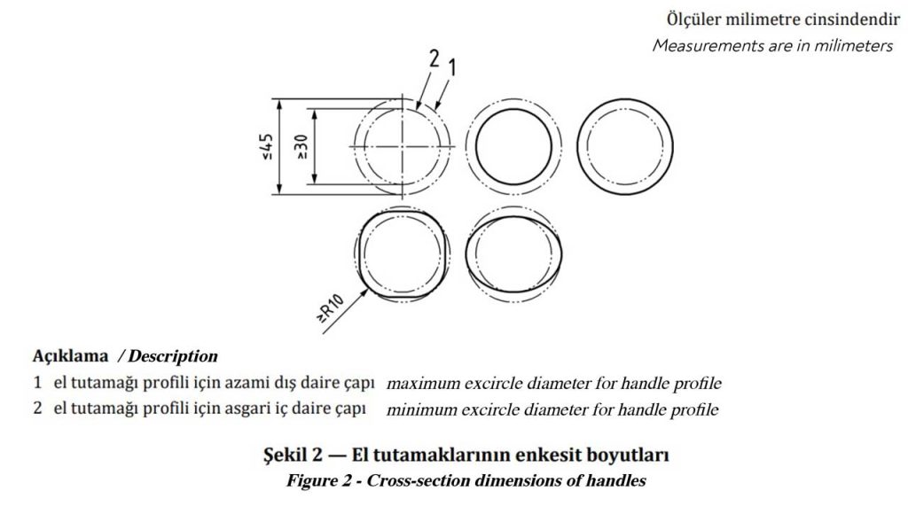
- In the car, there should be a handle on the wall where the control panel is located. The handle should be cut to avoid obstruction of the control panel. If the cut piece is smaller than 400 mm, it is sufficient to mount it on one side only. The gripping part of the handle should have cross-sectional dimensions between 30 mm and 45 mm and a minimum radius of 10 mm (Figure 2). The minimum distance between the wall and the handle should be 35 mm, and the distance between the top and the floor should be 900 mm ±25 mm vertically. The ends of the handle should be closed and directed towards the wall.
For car types 1, 2 and 3, the handle can be mounted on the opposite side wall if the handle restricts the width of the car entrance. For car types 4 and 5, a second handle should be mounted on the opposite side wall or on the rear wall.
- If there is a folding seat inside the car, the dimensions should be as follows:
- height 500 mm ±25 mm from the finished floor
- depth between 300-400 mm
- width between 400-500 mm
- The carrying capacity should be at least 120 kg.
- In the car, there should be a control panel complying with the criteria specified in the standard. Location of the control panel:
- In the center-opening doors, on the right as you enter the car
- For side opening doors, on the closing side of the door when entering the car
Cars with a width exceeding 1,600 mm should have control panels on both side walls.
In cars with adjoining doors, there should be a control panel on all walls without doors.
Source:
1) TS EN 81-20 (2020) / Safety rules for the construction and installation of lifts – Lifts for the transport of persons and goods – Part 20: Passenger and goods passenger lifts
2) TS ISO 8100-1 (2021) / Lifts for the transport of persons and goods – Part 1: Safety rules for the construction and installation of passenger and goods passenger lifts
3) TS EN 81-70 (2021) / Safety rules for the construction and installations of lifts – Particular applications for passenger and good passengers lifts – Part 70: Accessibility to lifts for persons including persons with disability
Get more of Elevator World. Sign up for our free e-newsletter.
