Cast-in Channel Connections
Sep 1, 2012

An examination of the use of hot-rolled, cast-in channels in elevator shafts
Connections in the elevator shaft are often subjected to demanding loading situations. For example, dynamic loading conditions, which have implications for the fatigue resistance of the connection, are common. Seismic and impact loads may also be considerations for the structure. Therefore, it should be checked to confirm the technical characteristics of the connection method are suitable for the load conditions they will experience. The condition of connections also needs to be checked to ensure they will be safe for long-term performance.
Welded connections to embedded steel plates and drilled connections are well known in the Indian construction industry as methods of attaching components to new concrete structures. However, in practice, these methods can be difficult to control on site, both in terms of location accuracy for the connection, and the reliability of its load-bearing performance. Neither method is fast or easy to work with when adjustment of connection locations is required. The accurate position of some elevator components is critical, and connection adjustment is often required to accommodate construction tolerances or facilitate the replacement and maintenance of equipment later during the life of the building.
For new structures, where concrete elevator shafts have to be poured, the pre-planned use of adjustable bolted connections to cast-in, hot-rolled channels can provide an improved experience for the designer, installer and client.
Cast-in Channel Types and Use
Cast-in channels are available in a variety of lengths, section sizes and types. The selection of products provides varying load ranges and channels with differing physical and technical properties. Steel channel profiles are normally either cold or hot rolled, with factory-connected anchors for providing anchorage within the concrete. The normal finish required for elevator shafts is hot-dip galvanized, but stainless-steel channels are also available. Connections to the embedded channels are normally made via twist-in T-bolts, although female locking plates or channel nuts are occasionally used with hex-head bolts. Typical products are shown in Figure 1.
The installation process of the system begins with the channels being placed in the face of new concrete elevator shafts when the concrete is being poured. When the concrete is hardened, the filler is removed, and T-head bolts are twisted into the channels, allowing the installation of components at any position along the length of the channel. The versatility of connection positioning in the channels allows accuracy. This adjustment feature is enhanced by the use of slotted brackets to provide component adjustment in other planes. The combined adjustment provided by the slotted brackets and the cast-in channel easily compensates for the inevitable construction tolerances. Figure 2 shows typical installation processes.
Connection Design Issues
The types of load applied to elevator connections can consist of some or all of the following: tension, shear, dynamic, seismic and impact loads. These loads can be applied via connections to structural components with different physical properties, such as concrete walls, floors and structural steel. In turn, the ability of concrete or block structural components to support applied loads will depend on their compressive strength, physical dimensions, edge distance to the connection and reinforcement design.
So, the ability of a connection to support imposed loads will depend both on its own physical properties and the structure’s ability to support and adequately distribute the loads. The design method utilized to select connections from the manufacturer’s technical information can be based on either applied stress design, or load and resistance factor design.
Steel cast-in anchor channels used to support these loads are produced by two main methods – cold and hot rolling. Both types are suitable for supporting static tension and transverse shear loads. However, for longitudinal shear loads (loads in the direction of the opening in the channel profile), dynamic, seismic and impact loads, hot-rolled profiles have better performance.
Due to the movement of elevator cars and doors in service, guide-rail, divider-beam and door connections are subject to dynamic loading. Side loads on the guide rail may also induce longitudinal shear loading in the cast-in channel connection. Depending on a building’s location and purpose, either seismic or impact loadings may also need to be accounted for in the design. For these reasons, hot-rolled, cast-in channels are typically preferred for critical connections in the elevator shaft.
Typical Connections in Elevator Shafts
Cast-in anchor channels can be used for almost any pre-planned connection to concrete. Before reviewing some of the more detailed aspects of elevator connection design, it may be useful to present how these products are typically used in elevator shafts.
The most common applications are for the anchoring of door gear, elevator guide rails and divider beams. However, cast-in anchor channels are also used in the shaft for structural connections, lifting-beam connections and services. In elevator lobby areas wall panels or artwork have also been supported using this method in order to gain the necessary location adjustment required for the connections.
Connections to the cast-in channels are provided by twist-in T-bolts. A line on the shank of the T-bolt serves as a safety indicator to show the T-bolt is fully locked in the channel.
Dynamic Loading Capabilities
Cyclical dynamic loading is a well-known cause of fatigue failure in steel components. Stress within the material used to fabricate the loaded component can be a contributor to early fatigue failure. Hot-rolled channels are produced in a manner that significantly reduces the in-built material stress created by most cold forming processes. Therefore, they are preferred over cold-rolled channel alternatives in a dynamic loading environment, where long-term connection reliability is a priority for safety reasons. Empirical testing has enabled the creation of accurate data to predict the allowable cyclical load variances acting on hot-rolled channels up to two million cycles. Recent developments in material fatigue modeling have also produced a mathematical basis for estimating dynamic performance when a life expectancy of more than two million cycles is required. Dynamic loading should be considered for both guide rail and door connections.
Longitudinal Loading
Longitudinal shear loading occurs when the shear load runs parallel with the opening in the cast-in channel. To prevent the connecting T-bolts from sliding along the channel under these loading conditions, high torques must be applied. For example, this type of load can occur when side loads are applied to elevator guide rails. The thick lips of hot-rolled channels enable high torques to be supported.
This feature also allows the use of nibbed T-bolts, which physically bite into the channel lip to provide enhanced resistance to longitudinal loads. Cold-rolled profiles normally cannot support the crushing forces associated with high bolt torques and are therefore not very effective in this loading condition.
Recent developments in hot-rolled channel technology have resulted in the development of cast-in channel profiles with serrated lips and T-bolts with matching serrated heads. The teeth on the T-bolt and channel mechanically interlock to resist longitudinal shear loads. This feature allows high longitudinal loads to be transferred and is the best solution for this loading condition. See Figure 4.
Seismic and Impact Loading
Recent testing has shown serrated hot-rolled channels with heavy-duty anchors perform well in simulated seismic and impact tests. These tests were conducted according to the requirements of the nuclear industry for safety relevant areas of the concrete structure. This testing also has application where the safe performance of the connection is required in seismically active areas, or where the building purpose requires resistance to explosions. In the testing regime, the HZA-PS range of serrated hot-rolled channels was subjected to short-duration cyclical loading up to normal capacity in heavily cracked concrete. The test samples were then fully loaded and deflection was measured. The results show consistent performance, even with severely cracked concrete at normal loads and a progressive yield at ultimate. This range of channels is also suitable for long-term dynamic and longitudinal loading. See Figure 13.
Connections to Different Types of Structure
While it is common to use continuous concrete walls to form new elevator shafts, other methods of construction are also used. Solid or hollow concrete blocks are quite often laid to form elevator shafts, and reliable connections with drilled bolts can be very difficult to make. In these cases, hot-rolled, cast-in channels can bring reliability to the connections if a concrete ring beam is cast at the levels required for the guide rails. See Figure 14.
Steel structures may require connections to the edge of thin composite floor slabs that utilize permanent metal formwork. Hot-rolled channels work well in small areas of concrete with tight edge distances to the connection. The performance of the hot-rolled channel can also be enhanced by using special anchors to allow the thin concrete elements to effectively transfer imposed loads into the structure. See Figure 15.
When adjustable connections to steel structural elements are required, hot-rolled channels are often surface welded or bolted, and perform well outside the concrete. In this case, care must be taken to provide adequate bearing for the connection bracket. See Figure 16.
Conclusions and Indications for Future Use
The use of hot-rolled channels in elevator shafts has to be planned prior to construction. This requires consensus and early decisions among a number of stakeholders. Although the system is more expensive in material than drilled bolts or weld plates, it is beneficial to the installation. The speed and accuracy of the system, combined with using simple tools without the need for power, convinces most installers of the system’s added value.
Engineers responsible for elevator safety recognize the value of a connection system with long-term performance that can be repeatedly installed safely. Clients and their elevator consultants prefer buildings to be completed quickly to reduce financing costs, and appreciate a connection system that allows quick replacement of defective components to minimize elevator downtime. The process of evaluating the benefits of this connection system is still in the early stages in some countries, like India. However, hot-rolled cast-in channels are in the process of being used for elevator connections at two high-rise buildings located at Kohinoor Square in Mumbai. The buildings are 52 stories and 32 stories high.
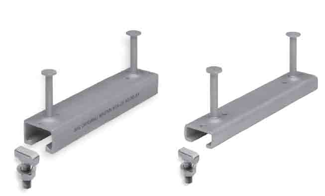
Figure 1: (l-r) Hot-rolled channel with thicker material at the opening of the profile and square corners, and cold-rolled channel with uniform material thickness around the profile. Pre-connected anchors provide anchorage for transferring loads applied to the channel into the concrete structure. Twist-in T-head bolts are used to provide adjustable connections to any point along the channel length. 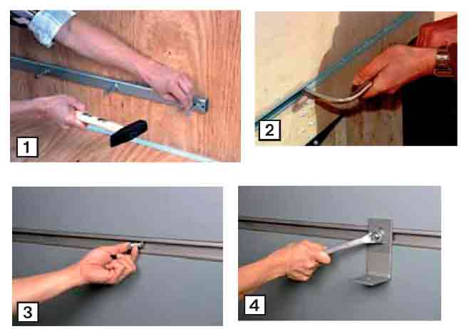
Figure 2: Installations: 1 Attach channel to formwork; 2 pour concrete; 3 remove channel filler; 4 twist-in T-bolt, tighten 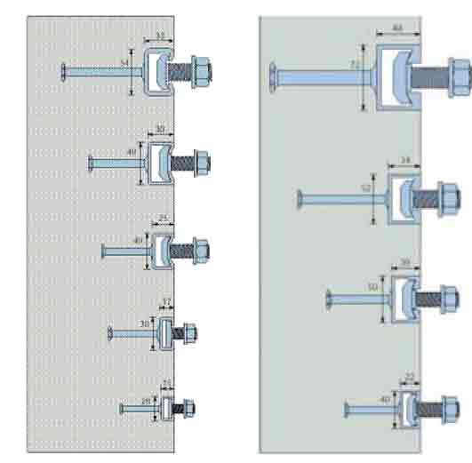
Figure 3: (l-r) Cold-rolled variants and hot-rolled, cast-in anchor channels: similar-sized channels of either type will have a similar static load performance. However, lower material stress and thicker channel lips enhance the performance of hot-rolled channels in dynamic and other load conditions. 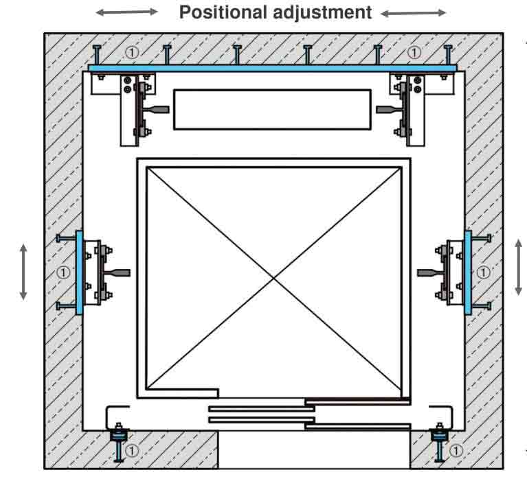
Figure 4: Schematic of a typical adjustment with bolted connections to hot-rolled, cast-in anchor channels (shown at locations marked ) for guide rails and doors 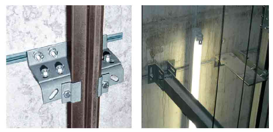
Figure 5: Hot-rolled, cast-in anchor-channel connections for guide-rail and divider beam connections provide location adjustment in one plane, with adjustment in other planes being provided by slotted brackets and rail clips. 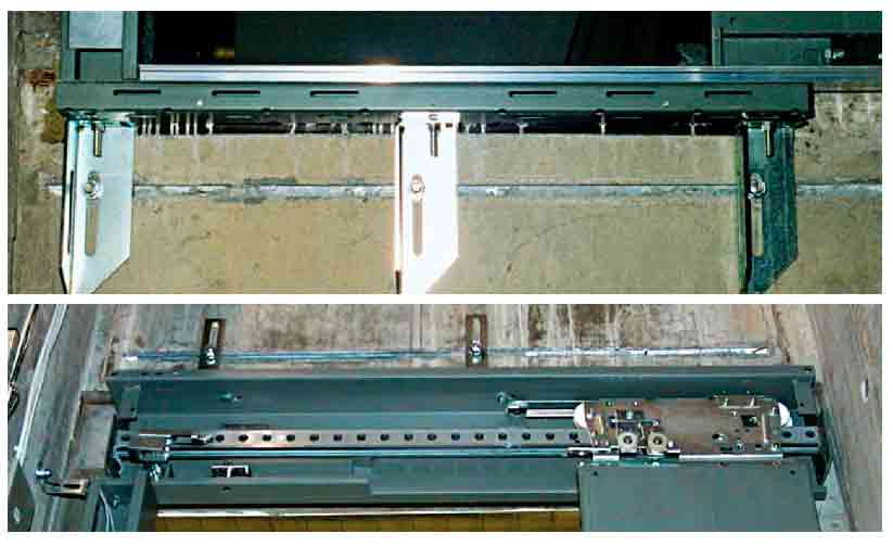
Figure 6: Connections at the head and threshold of doors using T-bolts into hot-rolled, cast-in anchor chan-nel for location adjustment. Adjustment in other planes is provided by slotted brackets. 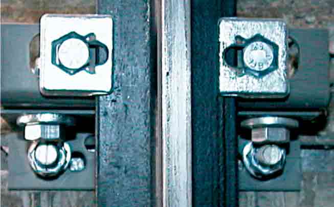
Figure 7: Vertical line on the shank of the T-bolt con-nection indicates the T-bolt is safely engaged with the cast-in channel. 
Figure 8: Dynamic loading cycle for one hot-rolled, cast-in channel frequently used in elevator shafts 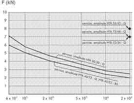
Figure 9: Allowable load variance for a range of hot-rolled channels up to 2 X 10⁶ cycles. The full S-N curves between 6 X 10⁴ and 2 X 10⁶ cycles are for two of the most popular hot-rolled, cast-in channels used in elevator shafts. 
Figure 10: Side loads (FY) on the guide rail will result in longitudinal loads (FL) on the T-bolt connection to the cast-in channel. 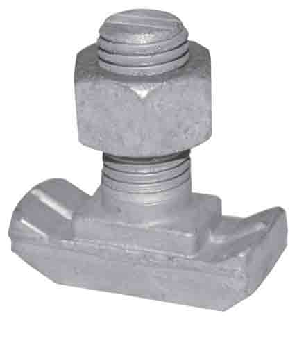
Figure 11: High torques combined with nibbed T-bolts produce longitudinal resis-tance in normal hot-rolled channels. 
Figure 12: Optimal longitudinal resistance is provided by hot-rolled serrated channels and T-bolts. 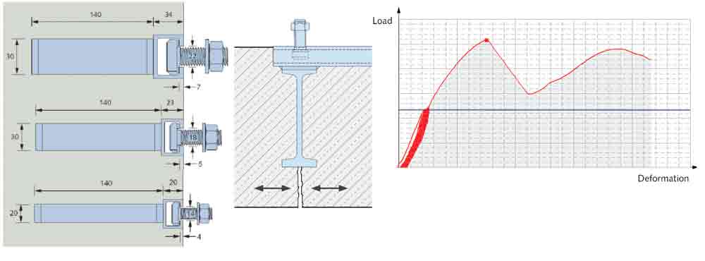
Figure 13: HZA-PS serrated channels tested in concrete se-verely cracked at the anchor. Cyclically loaded to working load while concrete cracking is actively varied between 1 and 1.5 mm in width. Ultimate loading at 1.5 mm crack width shows gradual yield to failure. 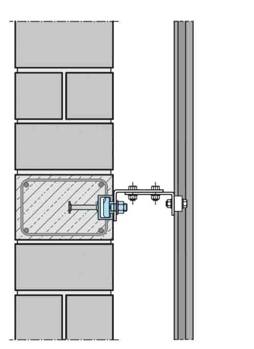
Figure 14: Hot-rolled channels cast into concrete ring beams in new con-crete block or brick elevator shafts 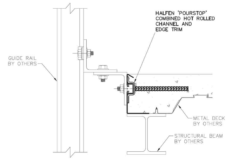
Figure 15: Hot-rolled channels with special anchors cast into the edge of a compos-ite floor slab
Get more of Elevator World. Sign up for our free e-newsletter.


