
A history of the often-forgotten component and its adaptations to technology over time
by John Inglis

Value: 1 contact hour (0.1 CEU)
This article is approved for Continuing Education by NAEC for CET® and CAT®.
EW Continuing Education is currently approved in the following states: AL, AR CO, FL, GA, IL, IN, KY, MD, MO, MS, MT, NJ, OK, PA, UT, VA, VT, WA, WI and WV | Canadian Province of BC & ON. Please check for specific course verification of approval at Elevator Books.
Learning Objectives
After reading this article, you should have learned about:
- Early counterweight designs
- Counterweight types, including crash weights, rod type weights and testing weights
- Typical guiding arrangements for counterweights
- Advantages and disadvantages of slab counterweights
- Weight comparison for counterweight materials
Abstract
This paper will review the evolution of the counterweight from the very early days, when man wanted to make his work easier. There have been many designs of counterweights used and adapted to cater to changes in technology. The counterweight tends to be the forgotten component in the total lift package. It is hoped that this [article] may inform and record this evolution for future generations.
Counterweight Designs Varied To Suit the Following Conditions:
- Improve efficiency
- Reduce machine shaft load
- Reduce power consumption
- Reduce differential loading
- Improve stopping accuracy
- Reduce the size of ropes on the machine
- Reduce traction problems
- Reduce the impact on the pit floor
- Reduce buffering at high speeds
- Improve ease of handling
- Decrease installation time
- Provide a means of adjusting the weight to suit the finished car
Typical Guiding Arrangements for Counterweights
- Wire guide fixed at top and bottom of shaft
- Wooden box containing a round or square weight
- Wood guide and backing timber used on many old installations and for current day units in an explosive environment
- Round steel either solid or tube guide shoes are either metal or plastic with metal housing
- Tee steel with flanged metal roller
- Channel
- Angle iron with various roller arrangements
- Series of rollers or guide blocks, fixed to the shaft wall, that work in conjunction with a length of guide rail on each side of counterweight. Guiding units on shaft wall are located close enough that there is always a minimum of two sets engaged on each side of counterweight.
- Tee steel rails in a variety of sizes and weights; the guide shoes are usually metal or metal with plastic inserts for slow speed lifts and rollers for higher speed lifts.
Guide Shoes as Part of Top and Bottom Weight
The very early counterweights ran on timber guides; the guide timber was a hard-wearing timber like tallowwood. This system allowed for very primitive guide shoes such as slots in the bottom and top weight. There was no guide shoe adjustment. Even in the early days of metal guide rails, the method of using the top and bottom weight as fixed guides applied.
Guide Shoes Incorporating Icebreakers
Counterweights in high towers exposed to the very cold environment had to be fitted with “ice breakers” or scrapers to keep the rails clean.
Counterweight Types
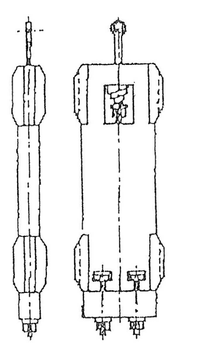
Crash Weight
The sketches show a very early method of reducing the impact on the pit floor in the event of suspension failure. This applied to smaller lifts where the counterweight was above occupied space. Its main disadvantage was that it was a “one-hit” solution that broke all the filler weights, which would have to be replaced. The breaking of the filler weights reduced the inertia in the system, so reducing the impact on the pit floor. The left-hand sketch shows the normal arrangement, the right–hand sketch shows the broken weights and the reduced height of the filler stack. The design of the fillers had to ensure that under normal counterweight buffer engagement the fillers did not break yet have spaces between the fillers to allow the maximum space for the broken fillers to occupy, so causing the maximum reduction in the filler stack.
Rod Type Weights
This type of weight construction was very popular in the early days of drum and traction lifts. It was used for a longer period of time with the smaller companies because of its flexibility and lower manufacturing involvement. The larger manufacturers with structural steel plants changed to the frame weight, particularly as lift speeds increased.
Testing Weights and Rope Anchorages
ln the early days of rod type counterweights, a variety of top weights (sometimes called king weights) were manufactured from cast iron. In many cases, these weights had the companies’ name cast onto them as shown in the sketch.
At an engineering lecture given in 1924, a method was described for casting wedge-shaped holes in this top weight for direct anchorage of ropes. This must have been one of the earliest applications of wedge-type sockets in the lift industry.
This introduction of rope anchorage and top weights was also subjected to a test for the strength of rope terminations and the top and bottom casting connected by the standard rods to be used. One of the tests carried out on a passenger lift weight resisted a strain equal to 30,000 kg.
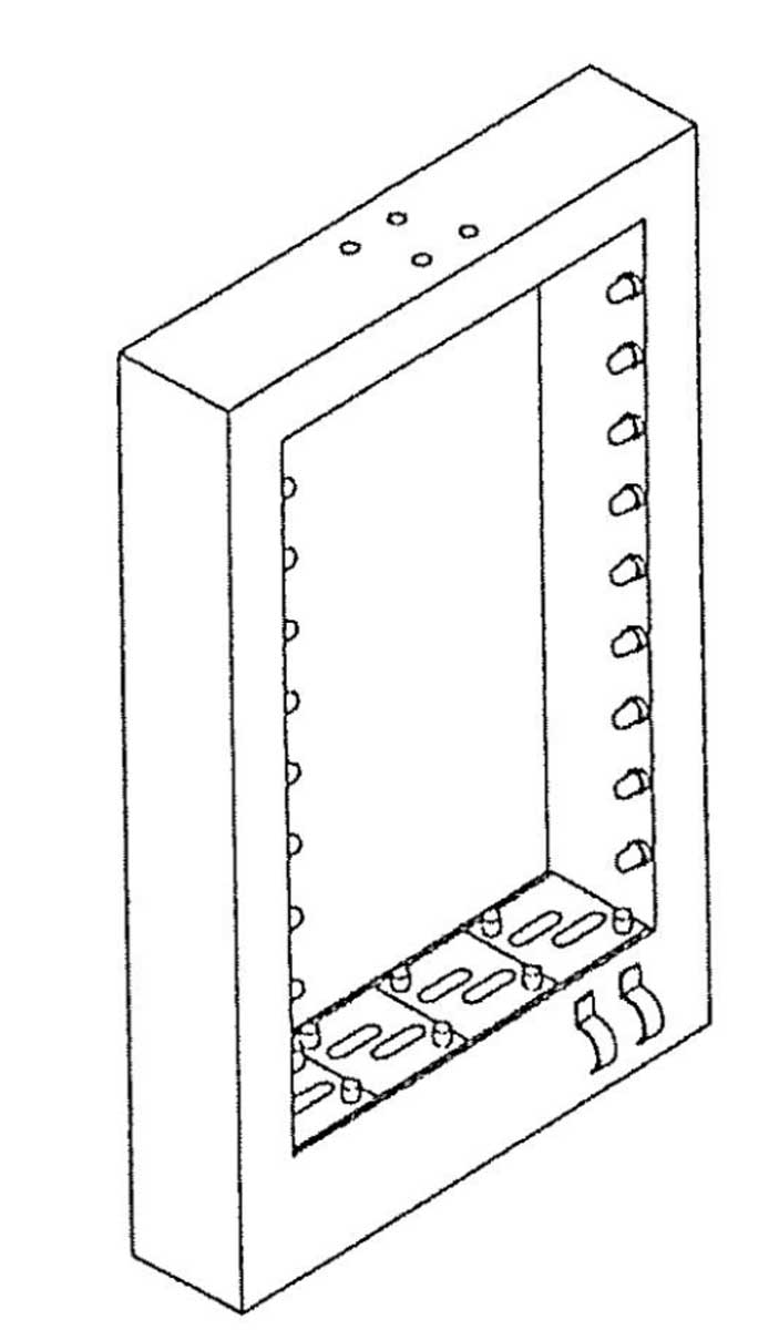
Framed Weight
After many countries had placed bans on rod type weights for high-speed lifts and lifts in earthquake areas, the most popular type of construction was the framed weight. In the days prior to arc welding, these frames were fabricated from channel iron and plate construction riveted together. The assembly of these counterweights in the field was much easier than the rod type construction and much safer for the construction worker. The rod type weight was very difficult to load the fillers onto the rods and maintain the stability of the partly built stack, which, unlike the framed weight, had no top guide shoes until the top weight was fitted.
Tank Weight
Tank weights were introduced as a cost reduction; also, castings were hard to obtain during World War II. The simplest description of a tank weight is that it is like a framed weight with each side covered with a steel plate making it into a box or tank. The idea was to fill the tank with scrap punchings; this allowed last-minute adjustment of the balance after the car linings were complete. A major problem arose in the early stages of application: the tanks started to expand in thickness due to the punchings packing down from hard stopping of the lift and, more importantly, from counterweight buffer engagement. There were several cases of the tank side bowing out and breaking the welding. This effect was caused by the packing down of the contents to such an extent that the sides of the tank bulged.
The increase in tank thickness reduces the running clearance between the tank and car and, in some cases, between the tank and shaft wall.
The size of the tank had to be considerably larger than those counterweights using cast iron fillers, because the efficiency of filling the space inside the tank depended on the size and shape of the scrap punchings. Rust was another unexpected problem. The amount of rust, or the speed with which the rust developed, depended on the material that was punched and the oil/cutting lubricant used to increase the life of the punches.
Slab Counterweights
The use of a single piece counterweight has both advantages and disadvantages that should be considered before deciding on this form of counterweight construction.
Advantages of Slab Weights
- It is a compact unit that can be made into a suitable shape for the application, e.g., long and thin, short and thick, or shaped.
- It can be used on model lifts where specific weights of the car are known and adjusting the weight is not required.
- It does not bend in earthquake situations like multiple weights in the rod type construction.
Disadvantages of Slab Weights
It is not easy to add or subtract additional weights except at the bottom of the weight assembly. It is very difficult to handle. It can easily damage door frames or door sills when being moved into the shaft.
Reduction of Power Consumption
During wartime in Australia, many lifts had their counterweights reduced to car weight plus 40% of the load, in place of car weight plus 50%, which had been the common practice. This was designed to reduce power consumption based on the fact that lifts very rarely carried maximum load. In some cases, this was not possible due to the traction ratio between car and counterweight.
Counterweight Running Clearance
There is always the argument on how much well space is available for lifts; the client wants the maximum rentable space, and the lift contractor requires suitable running clearances. The space between the car and counterweight can be as low as 25 mm for many low-speed lifts, but for high-speed lifts, this must be increased to reduce the buffeting effect as the counterweight and car pass. In some cases, a clearance of 100 mm, in conjunction with a counterweight design that has aerodynamic shape, should improve the air flow and reduce turbulence.
Weight Comparison for Counterweight Materials
For many years now, companies have used different materials to provide the major portion of the weight of a counterweight assembly. The selection of these materials has been based on price, availability, transport costs and means of adjusting the balance at the completion of the cabin interior. It is necessary to consider the above and the space available, as the less dense material takes up considerably more space for the equivalent weight. The most common material used has been cast iron; other materials have been steel, lead, concrete and combinations of these.
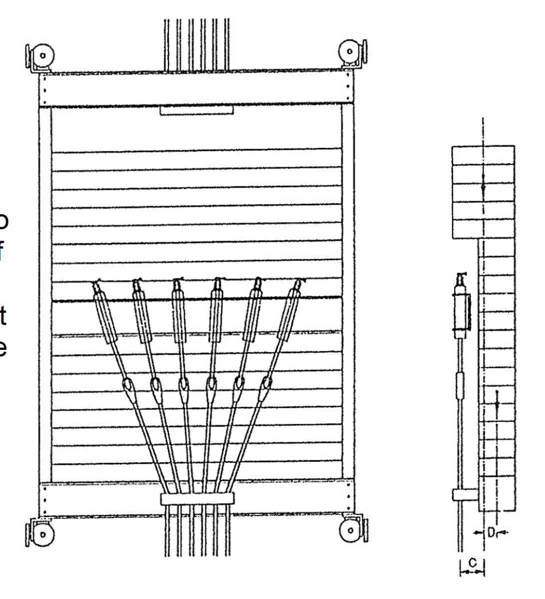
Multi Line of Fillers
For very large lifts, the counterweight fillers became too heavy to handle; this required counterweight frames to be designed to hold several rows of filler weights. This practice also allowed manufacturers to use their smaller weights in the multi row assemblies rather than make special large weights that were not used very often.
Sand in tank
There have been cases of counterweights being filled with sand so the correct or required balance could be achieved. This practice was short-lived due to two major problems: the sand leaked out through small holes, and the weight of the sand changed due to moisture being absorbed into the sand or the sand drying out.
Drum Machine Counterweights
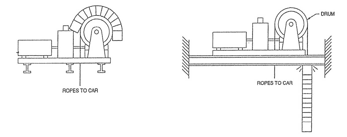
Why was the counterweight removed from drum-type lifts? The major accidents associated with counterweights and drum machines were the results of the adjustment or failure of the limit switches, even though most of these were made a part of the machine to ensure positive action.
In some cases, the machine overwound and pulled the counterweight into the machine room. The machine beam location can prevent the counterweight being pulled into the machine room, but at the same time, it brings the counterweight to an abrupt stop. This sudden stop has been the cause of many ropes breaking or terminations failing, thus allowing the counterweight to freefall to the pit.
Jamming of the car in the shaft on a down direction run has allowed ropes to become slack, stopping the machine by opening of the slack rope switch. This situation has not been foolproof; there have been cases of lift mechanics operating the controls manually and winding rope off the drum, and then winding the rope back onto the drum in the wrong direction.
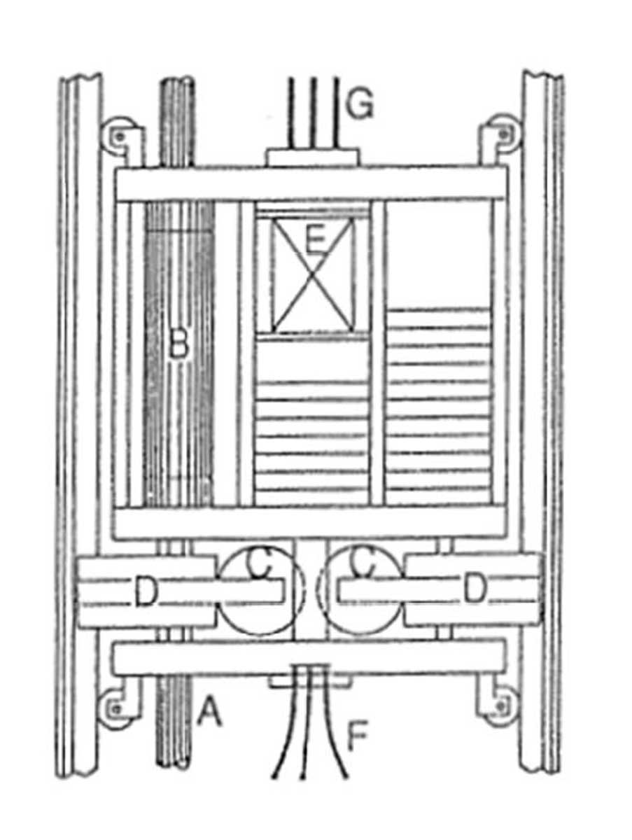
Prior to the counterweights being forbidden on drum-driven lifts, two counterweights were installed in the same guides. The bottom weight was for the car, and the ropes passed through the top weight. The top weight was fitted for two reasons: to reduce the load on the drum machine and to avoid larger or additional ropes being required.
Single pickup counterweights have failed, allowing the counterweight to free fall to the pit. Even though there were two ropes between the machine and counterweight, attachment was via an equalizer bar that only had one point of connection to the counterweight.
Counterweights Coming Out of the Guide Rails
There are several reasons for counterweights coming out of the guide rails; first, earthquakes can cause the distance between the guide to be increased to such an extent that the guide shoes become disengaged.
The guide rail separation can be due to failure or loosening of rail brackets, many of which have slotted, fixing holes for adjustment during installation.
In some cases, the brackets are independent, and the building construction fails between two brackets at the same level.
Another reason for counterweights coming out of the guide rails is buckling of the rails due to the rails ending up too close to the underside of the machine room floor and building compression causing loading on the top of the rails. This loading has buckled the rails to the extent that the distance between rails has increased.
Guide shoe or roller engagement is very important, particularly on small rail sizes. In an endeavor to maintain a suitable clearance between the guide shoe or roller shoe safety bracket and the rail holding clips, some designers have made the error of reducing the amount of engagement onto the smaller guide rails.
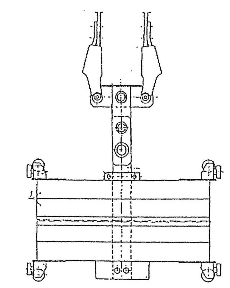
During earthquakes, it is possible for the counterweight to come out of its guides; with a lift traveling at fast speed, this can be a major disaster. To protect against this, a displacement detector, like that shown in the sketch, will stop the lift when the sensing ring on the counterweight touches the sensing wire.
Counterweight Bounce (Anti-Rebound Device)
In recent years, there has been much concern about the forces developed when safety gear operates on high-rise lifts, causing considerable counterweight bounce. Designers are currently working on finding a solution to this serious problem, mainly with installations without lock-down compensation.
Buffers Mounted Below Counterweight
The addition of oil buffers to the bottom of counterweights gave additional weight to the counterweight; this, in turn, reduced the weight of fillers to be used by the weight of the buffer assembly. Gravity caused the buffer to reset as the counterweight was moved up off the pit stop.

Safety Gear on Counterweights
The addition of safety gear to counterweights is often required to suit the following emergencies: to prevent runaway cars and to prevent free fall of the counterweight in the event of suspension failure. Depending on the contract speed, the safety gear can be instantaneous, sliding or oil cushion types.
Wedge clamp safety gear on a counterweight causes a major problem regarding the resetting of the equipment after it has operated. One method of overcoming this problem is by having the rope drum with a rope coming off each side; that is, one rope on the topside of the drum that pulls the safety gear onto the rails and the other rope at the bottom at the same time winding onto the drum. To release the safety gear, the mechanic can enter the pit and pull on the rope that connects to the bottom of the drum. This will unwind the safety gear and, at the same time, reset the top actuating rope. This arrangement can be released if the suspension means has failed, but if released completely, the counterweight will descend at excessive speed, causing the governor to operate and reset the safety gear.
Duplex Safety Gear
The space available in lift shafts is usually limited in the plan view, yet, in most cases, the elevation is not so restrictive. For large lifts that require safety gear to be fitted to the counterweight, the standard safety gear may be too large in the plan dimensions. This is where duplex safety gear can be fitted: a counterweight frame fitted with two safety blocks at each end. This type of safety gear resets by moving the car in the upward direction. Normally, the safety gear blocks are of equal capacity, but if unequal capacity pairs are used, the larger capacity should be fitted to the bottom of the counterweight frame.
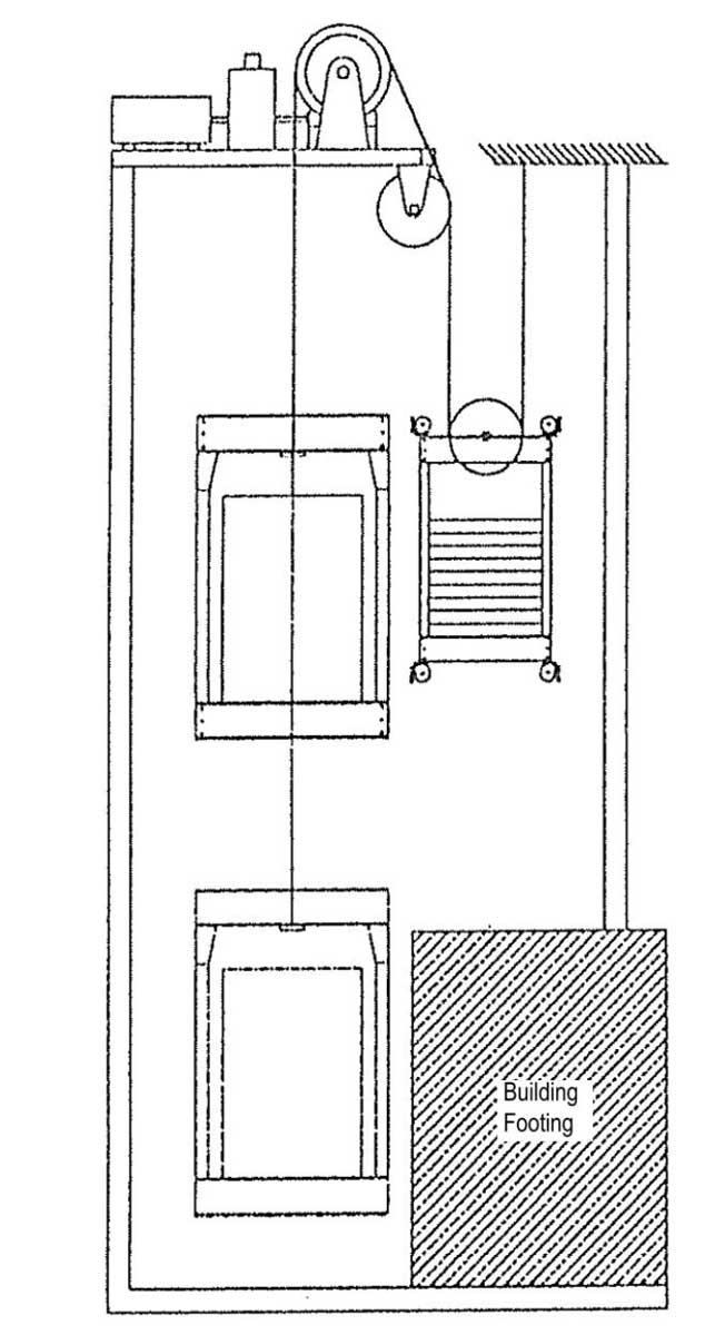
Counterweight Roping Ratio Change To Suit Building Footings
Building footing has often caused the elevator installer major problems. For example, when a particular pit was excavated, large footings were found that could not be removed. These obstructions were below the path of the counterweight reducing the required travel. By roping the counterweight 2:1 and leaving the car at 1:1, the problem was solved.
This solution has some drawbacks in that the counterweight is now required to be twice the previously required weight due to the 2:1 roping, but it only travels half the distance of the car.
Compensation Rope or Chain Attachment
Following the increased height of buildings, chain compensation was followed by rope compensation. This then required compensating ropes to be attached to the counterweight. Initially, the ropes were connected to the underside of the counterweight, but as this required additional pit depth, the ropes were connected to the face of the counterweight. This reduced pit depth but increased the distance between the car and counterweight. Some manufacturers recessed the compensating rope attachments into the front face of the counterweight. Care had to be taken with the location of guide shoes to minimize the shoe loadings; depending on the height of the building, the loading on shoes changed from the weight of the compensating ropes; this was partly offset by moving the shoe center line closer to the rope center line and allowing the offset of the counterweight to provide a counteracting load.
Counterweights for Architectural Effect
There is an application in Australia where there is a large viewing hole through the center of the counterweight. Around the inside of the hole are lights run from a bank of batteries located in the bottom of the weight. There are two spring-loaded contacts on the weight for connection to a battery charging unit each time the lift parks at a terminal floor. Because of the large space taken up by the viewing hole, the perimeter of the weight is longer than normal to provide the required weight for balance.
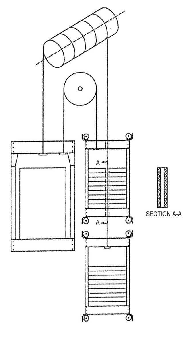
Tension Weight
Designers may be faced with a situation where the falling of an uncontrolled weight could have devastating effects. An example was where a lift shaft was located directly above the main pipeline supplying water to a city. A second problem was there was not enough space in the shaft for a counterweight fitted with safety gear. A tension weight method was used where the weight was outside the line of the shaft at the top landing, and there was a fixed sheave in the pit.
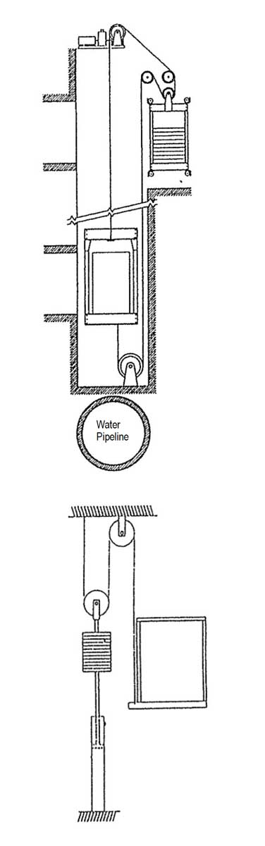
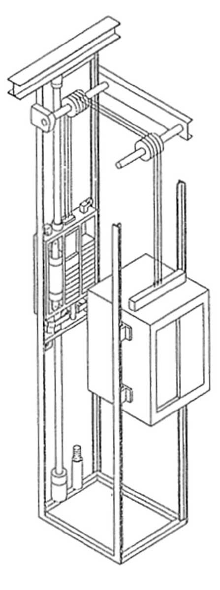
Counterweights on Indirect Hydraulic Lifts
The main advantage of such a counterweight arrangement is to reduce the power required to raise the fully loaded car. Care must be taken to ensure that half the weight, including ram and sheave, is not excessive (for 1:2 roping). An approximate guide is 60% of the empty car weight; otherwise, the empty car will not descend on its own.
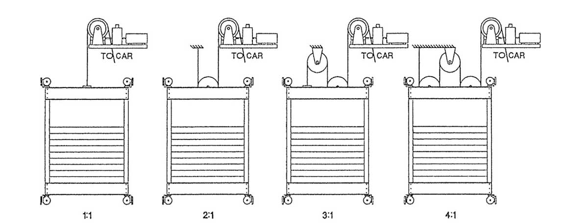
Roping Ratio for Heavy-Duty Applications
2:1, 3:1 and 4:1 roped machines allow smaller machines to be used, but as the ratio increases, the rope life is reduced due to the number of reverse bends.
Machine sheave speed can be very high when using 4:1 roping of counterweight and car.
Linear Motor and Counterweight
The earlier developments of the linear motor drive system placed the motor on the lift car, which increases the load on the ropes and machine shaft. Next, it was added to the counterweight, which reduced the load on ropes and machine.
The latest version first included the brake into the counterweight, then proposed that as ropes are now so reliable, the safety gear could be dispensed with on the lift car, as the brake on the counterweight could stop and hold the lift.
The overall situation with the linear motor built into the counterweight is as follows:
Advantages of Linear Motor
- No conventional lift machine is required.
- No machine room required, only a sheave room at the top of the shaft.
- No traction sheave to reduce rope life.
- Reduced loading on the building due to reduced total equipment weight.
- The brake on counterweight can also be used in place of safety gear.
- Within limits, the higher the rise the more cost effective is the system.
- Reduced building height requirements may permit serving another floor at the top of the shaft without encroaching on the building height restrictions.
Disadvantages of Linear Motor
- Traveling cables are now required also to counterweight, with current ratings to supply the linear motor.
- Counterweight space requirements are increased.
- Without safety gear on the lift, car free fall in the event of suspension failure is not prevented.
- Access to the linear motor is not easy if something fails e.g., power or fault develops when the counterweight is in the middle of the shaft and the car cannot be moved to access the linear motor
- The efficiency of the linear motor is low but should improve with R&D.
- Supporting of the linear motor rotor on high-rise lifts may be difficult.
Learning-Reinforcement Questions
Use the below learning-reinforcement questions to study for the Continuing Education Assessment Exam available online at Elevator Books or on p. 111 of this issue.
- What are some of the typical guiding arrangements for counterweights?
- What conditions did the various counterweight designs aim to suit?
- What are the advantages and disadvantages of a linear motor built into the counterweight?
- What are some of the reasons counterweights come out of the guide rails?
- Why was the counterweight removed from drum-type lifts?
Get more of Elevator World. Sign up for our free e-newsletter.


