Curving and Continuous Elevator Systems
Jun 1, 2014

An examination of early 20th-century quests for our industry’s “Holy Grail”
Almost every profession has a list of unique and elusive goals that constitute what may be thought of as “Holy Grail” projects. These projects typically involve an arduous and difficult search for something that always appears to be just beyond the reach of its pursuers. In the realm of vertical transportation, these types of projects include elevators that travel along curving shafts and elevators that effortlessly move vertically and horizontally through a building. The examination of two designs from the early 20th century that addressed these elevator system types will illustrate the perceived benefits to be gained in obtaining these particular Holy Grails, as well as the difficulty of actually achieving these goals: as will be seen, in both cases the imagination and ambitions of the inventors proved to be no match for reality. These efforts are, however, worthy of study, because, sometimes, the journey is more important than the destination.
On February 3, 1903, San Francisco architect Daniel E. Condon patented a new elevator system: “Spiral Elevator,” U.S. Patent 719,751. He described his invention as being related to “traction devices” and stated his intention was “to provide a new and improved spiral elevator for use in observatories, rotundas of high buildings, and the like designed for pleasure trips, for business, industrial and other purposes.” And, as was common practice at this time, he stated that his design was “arranged to ensure perfect safety to the passengers making use of the elevator.” The majority of the patent’s 16 illustrations concerned the elevator’s use in observation towers; thus, Condon may have initially conceived of his design as solely intended for “pleasure trips” (Figure 1). This proposed use gave Condon greater freedom in his design approach, as he appears to have conceived of his scheme as equal parts “ride” and “elevator.”
His design employed a spiral “endless track” that carried a series of “trucks” linked together, which, in turn, formed an “endless train.” The train carried a series of suspended elevator cars (Figure 2). Condon described the system’s basic configuration as follows:
“The spiral up and down runs may be of the same or different pitch, preferably, however, of the same pitch, as shown in the drawings. . . . It will be seen that the runs pass each other at every convolution on opposite sides of the framework, between the base and top thereof. Passengers in one car thus pass close to the passengers in another car running in an opposite direction, so that the up and down journey in a car will be greatly enjoyed by the passengers. On a car reaching the top, the passengers may alight on the framework platform to view the surrounding country or scenery from the top of the tower, and the passengers can take the same or another car for the down journey. On a tower having spiral runs of ordinary grade — say 10-20% — long cars with two- or more-axle trucks may be employed; but on a tower having a track of a very steep grade (over 20%), I prefer to use short cars with single-axle trucks for the cars to hang perpendicular during the entire journey.”
Condon proposed that the system would be “set intermittently in motion,” with cars stopping “simultaneously on each station and the top platform of the tower for passengers to embark and disembark.” Safety was ensured by the presence of “suitable brake devices” attached to each car. The brakes were controlled by an “attendant” or car operator; thus, “in case of derangement of the actuating machinery,” the cars could “be stopped at any point of the track or slowly run down to the starting point at the station.”
Condon claimed that the power required to operate the endless train of elevator cars was approximately equal to the power “required to haul a corresponding train on a level track, as the weight of the cars on the down-run practically balances that of the cars traveling on the up-run.” Power was provided by “a motor of any approved construction,” which was located in a “powerhouse” located at the base of the observation tower. The motor drove a power wheel that was composed of an inner annular gear-wheel and an outer spur gear-wheel. The trucks engaged the outer spur gear and were guided through their movement by a “segmental internal gear wheel” (the gear-arc located to the left of the power wheel: Figures 3 and 4). Condon believed his design would allow passengers to be “quickly taken up or down. . . without undue loss of time, as one set of cars is always going up, while at the same time, another set of cars is going down.” It was, perhaps, this imagined efficiency that prompted him to include his final patent illustration, which depicted his invention situated in an office building (Figure 5). In this setting, the powerhouse was located in the basement, and the elevator operated on the same intermittent schedule proposed for the observatory.
The prospect of applying his invention to office buildings may have prompted Condon to pursue a second patent for his spiral elevator system: “Elevator,” U.S. Patent 755,361 (March 22, 1904). In this patent, he avoided references to “pleasure” travel and focused his attention on the world of business:
“The object of the present invention is to provide a new and improved elevator designed for use in all classes of modern business and industrial buildings in which large crowds of people (and freight, etc.) have to be carried to, from and between the various floors in the safest, most expeditious and systematic manner possible.”
The first illustration echoed the final image of his initial patent in its depiction of a spiral elevator employed in an office building (Figure 6). However, its proposed operation was very different from the earlier scheme. Whereas the first design had proposed intermittent operation, with the cars stopping and starting at set intervals, the revised design was “arranged for continuous travel of the cars from one floor to another in the building, at the same time enabling the passengers to readily leave or enter the cars at any floor of the building.” The suggested operation speed was 60-90 fpm, which he believed to be slow enough “to allow the passengers to readily step into and out of the cars at the landings.”
Thus, Condon’s revised design could be characterized as a variation of the paternoster elevator, with the primary difference being the distance between the up and down shafts. However, the remaining 11 patent images concerned a variation of his invention that extended the idea of the continuous elevator into an entirely new realm. This new direction is effectively illustrated by a drawing that depicted a series of cars traveling along a gentle diagonal slope, which resembled the travel path typically associated with escalators (Figure 7). Condon further illustrated this application of his idea in two different configurations:
- As a continuous system that flowed up and down through a building in a continuously rising horizontal line
- As a system that scissored vertically back and forth through a building (Figures 8 and 9)
Both drawings depicted the train of elevator cars moving through what appeared to be an extruded, wire-mesh-covered elevator “shaft” that featured openings at each floor level and permitted passengers to exit and enter the cars. The plan of the scissor scheme also depicted separate elongated spiral paths for the ascending and descending cars, with the two paths linked at the top.
Condon’s efforts were followed three years later by Belgian engineer Jules Gernaert (1862-1912). In April 1906, Gernaert filed a patent application titled “High Building,” which proposed an innovative approach to skyscraper design and construction. The patent was awarded on June 25, 1907 (U.S. Patent 858,170). Gernaert stated that his design concerned “improvements in building construction,” which were “especially adapted for use in the thickly populated districts of large cities.” The designer’s primary goals were to:
- “Erect a structure that will occupy a minimum area of ground space”
- Provide a “maximum area for residence or business occupation”
- “Construct a building that will not greatly interfere with street traffic”
- Provide “the greatest possible amount of light and ventilation” for the building’s occupants
As depicted in his patent illustrations, Gernaert’s design resembled a slender, giant arch (Figure 10). A curved elevator shaft traversed the arch from side to side. The combined elevation and section drawing illustrated two possible configurations: the car could either be suspended from the curving track or attached to its side (Figure 11). The drawing also clearly indicated the schematic character of this aspect of Gernaert’s scheme, revealing the fact that he had only a limited understanding of the technical challenges involved in constructing his curving elevator.
The imaginative character of Gernaert’s design briefly captured the attention of a broad American audience. On May 27, 1906, one month after he had filed his patent application, New York World published an article by its Brussels correspondent that described Gernaert’s new “rainbow-form for buildings.” The article also made a specific reference to a supposed attribute of the design not mentioned in his patent. Gernaert now claimed that because his building touched the ground on only two distinct “resting points,” it had an elasticity that was a “safeguard against damage by earthquakes.”
This topic was of great interest to the American public. The devastating San Francisco earthquake had occurred approximately one month earlier on April 18, 1906. New York World’s article was picked up by the Associated Press and appeared in newspapers across the U.S., many of which included the elevation drawing found in Gernaert’s patent (Figure 10). Several of the articles reported, “A combination of elevator and trolley car will carry tenants to the various floors.” The interpretation of Gernaert’s elevator design as a trolley car revealed the unique, and, perhaps, almost ride-like quality associated with his curving elevator.
Gernaert and Condon both understood the potential offered by elevators that deviated from standard vertical systems. Although Gernaert’s schematic design avoided answering questions about its construction and operation, its simplicity matched the dynamic form of his rainbow skyscraper: the building employed a vast curving shape that dictated the path of the elevator’s movement. Condon’s imaginative combination of the paternoster’s continuous movement and the escalator’s travel path produced a design that almost achieved the goal of moving both vertically and horizontally. Thus, both inventors may have seen (or at least imagined they had seen) their particular Holy Grail. And, of course, as often happens with this type of quest, they failed to achieve their ultimate goal.
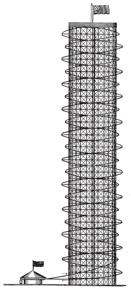
Figure 1: Observation Tower, Daniel E. Condon, “Spiral Elevator” 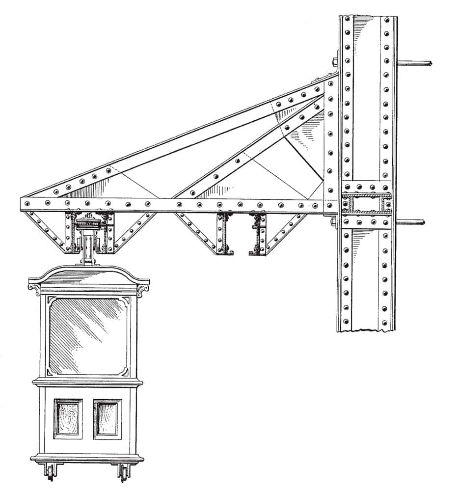
Figure 2: Observation Tower Elevator Car, Condon, “Spiral Elevator” 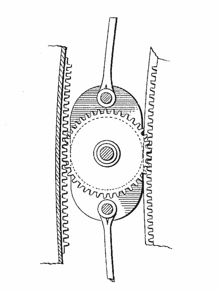
Figure 4: Detail of Truck Gearing, Condon, “Spiral Elevator” 
Figure 5: Office Building Installation, Condon, “Spiral Elevator” 
Figure 6: Office Building Installation, Condon, “Elevator” 
Figure 7: Elevator Car-Train, Condon, “Elevator” 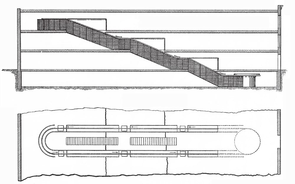
Figure 8: Horizontal Continuous Elevator Installation, Condon, “Elevator” 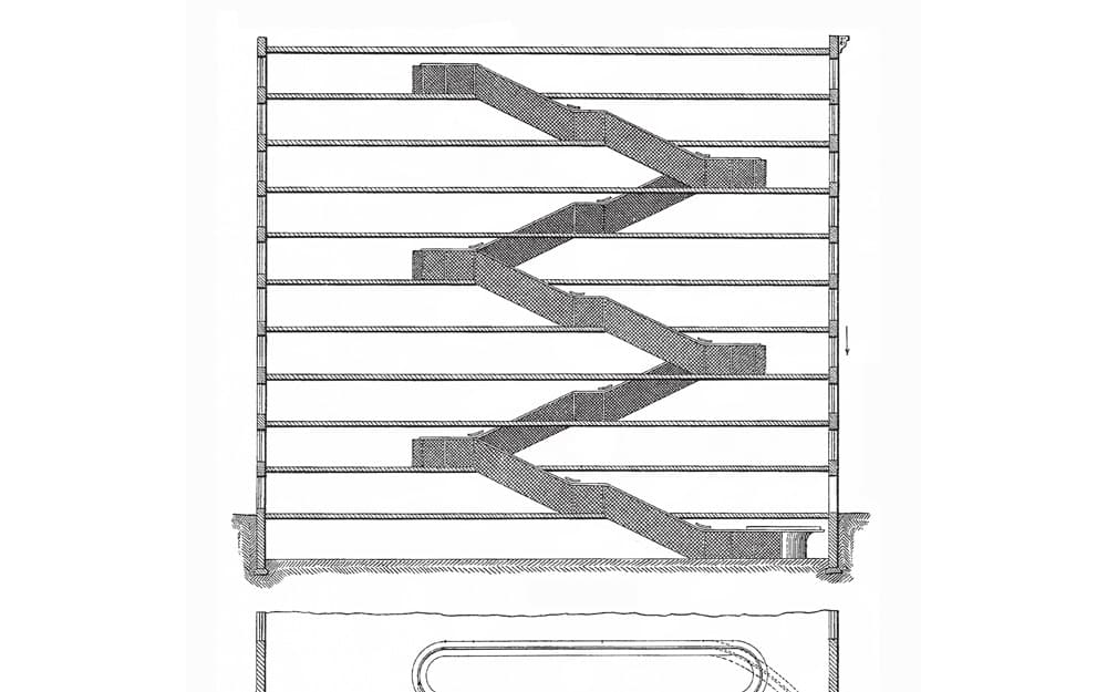
Figure 9: Scissor Continuous Elevator Installation, Condon, “Elevator” 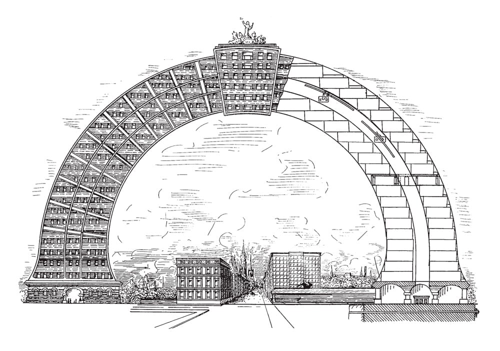
Figure 10: Elevation/Section Drawing, Jules Gernaert, “High Building” 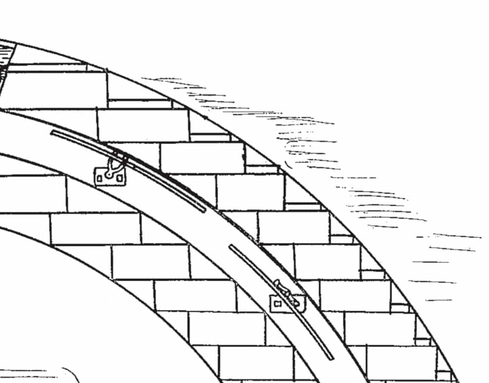
Figure 11: Elevator Detail, Gernaert, “High Building”

Get more of Elevator World. Sign up for our free e-newsletter.


