Design Parameters and Stress Analysis of Elevator Guide Rail Brackets
Jun 1, 2011
This engineering research provides a look at the various aspects of guide rails and how important they are to elevator safety.
by Serhat Koç, Dr. C. Erdem Imrak and Sefa Targit
Abstract
Elevator systems consist of too many components and guide rails are the most important ones in terms of elevator safety. For a safe, smooth and comfortable travel, guide rail bracket is one of the most important components along with guide rails. Guide rail brackets are used for installing the guide rails on the wall. In this study, results of guide rail calculation for different loading situations and analyzed guide rail brackets and clips were commented on.
1.Introduction
In practice the guide rails of the car are fixed in two different ways, at the top of the well (hanging guide rail) or at the pit and guide rail brackets are positioned at regular distances from each other along the rail to support the rail. Safety device operations are important in guide rail calculations (Day, 2000; Imrak et al, 2006). In this operation, it is very important to fix the car at the pit reg-ularly. If the guide rail is not properly fixed at the pit while the safety de-vice operations, the guide rail brackets are subjected extreme vertical loads. These situations are modelled in this study by using finite element analysis with ABAQUS/CAE 6.6-1 software and the stress distribution on the guide rail brackets is obtained in order to analyze the static behaviour (Koç, 2009).
Elevator guide rails and its peripherals, and safety gears are the most important components of the elevator system that needs high safety requirements. Under normal circum-stances, guide rails simply define the elevator paths that elevators ride along and are assumed to be spared from the loads and forces imposed on the elevator cars (Demirsoz et al, 2005). During elevator travel, the forces will be comparatively low, especially if the car is well balanced and the load is well distributed. The other loads exerted on the rails will be from safety gear operation under emergency conditions (Targit, 2002). The exerted loads can be very high, depending on safety gear type (Imrak et al 2006).
Considerable research studies have been carried out about elevator guide rails and safety gears as discussed in (Imrak et al 2008a). But in the literature, limited studies about guide rail brackets and clips have been published.
2. Guide Rail Bracket
Elevator systems typically include an elevator car that travels in a vertical direction within a hoistway. Typically, an elevator system includes guide rails mounted within a hoist-way for guiding an elevator car and counterweight during movement be-tween floors of a building. The guide rails are secured to the hoistway walls or structural beams by mounting brackets. The mounting brackets are spaced apart from each other at defined intervals along the guide rail to support the guide rail and pro-vided a sufficiently rigid mounting (Koç, 2009).
An elevator rail mounting system for positioning a pair of elevator guide rails, capable of centring an elevator car there between, in a hoistway comprises a L-shaped bracket, mountable in the hoistway an adjustable distance from the entrance side thereof, for fixing the angular relationships of and distances between the guide rails, a landing sill and a hall door frame to insure a constant running clearance between the elevator cab and the landing sill and to maintain the proper alignment of the elevator cab and the hall door frame.
The L-shaped bracket includes a horizontally and vertically adjustable cross member mounted from the entrance side of the hoistway substantially adjacent and parallel thereto. A pair of parallel rail brackets, spaced apart by a predetermined distance and extending into the hoistway perpendicularly from the cross member, support the guide rails in a vertical plane substantially parallel to the entrance side of the hoistway and maintain the distance between the guide rails at a predetermined fixed value.
Guide fixing bracket, comprising at least a body part, rail clips and tightening elements, characterized in that at least one of the guide rails is fixed in place by means of guide fixing brackets. Guide fixing bracket has at least one tightening element, preferably a bolt, for fastening and tightening the rail clips and holding at least one guide rail in place, and that the guide fixing bracket has only one tightening element for one guide rail to be fixed. Guide fixing bracket is made of St37 and comprises at least a support plate which is provided with fitting places for the guide rails and which can be fitted to the body part.
The guide rail is typically a T-shaped beam having a flange portion secured to the mounting brackets, which are secured to the wall or structural beams. The mounting brackets typically comprise rail clips overlapping that portion of the guide rail fastened to the wall or another structural beam within the hoistway. The mounting brackets and the two rail clips secure, trap and clamp the flange portion of the guide rail against an inner wall or structural beam within the hoistway.
During installation, the guide rail must be moved into a proper mounting position before the brackets can be fixed to secure the guide rail in place. The brackets often turn with movement of the guide rail causing an undesirable twisting and locking of the clips against the guide rail. Further, movement of the guide rail for alignment and to compensate for inconsistencies in the guide rail are not easily accommodated with conventional rail clips.
Accordingly, it is desirable to develop and design a mounting bracket that is adjustable to accommodate different size guide rails, and that can be movably secured to the guide rail to aid in installation within a hoistway.
3. Modeling the System
The finite element method is a numerical procedure that can be applied to obtain solutions to a variety of problems in engineering. The accurate prediction of the stresses experienced on the guide rails can be obtained only through the application of computational engineering techniques. Finite element solutions to guide rail and brackets constitute mainly static two-dimensional approaches to the stresses (Moaveni, 1999). In order to analyze the static behavior of guide rail and bracket system during the safety gear operation, required parameters about the car, guide rail for this study are given in Table 1.
The loads acting on the guide rails are calculated according to the EN81-1 for descending safety gear operation. Elevator guide rail data gathered from ASRAY Inc. where mass production of elevator guide rails is made have been used.
The finite element model of the system consists of 37773 nodes, 16476 four-node tetrahedral elements (C3D49) and 22736 eight-node brick element with reduced integration (C3D8R), totally 39212 elements. The solid model and finite element model of the system are shown in Figure 1.
The discretization of the guide rail, bracket and clips are performed using 3-D finite elements C3D8R which are saved in the library of the CAD software. It is an element suitable for analyzing slender to moderately thick beam structures. This element is also based on 8-node linear brick and reduced integration with hourglass control. The ABAQUS C3D8R element is inaccurate with one thickness element but as this number increased the results improved.
The guide rail and brackets were modelled as deformable part and clips were modelled as non deformable rigid part in finite element modelling. Explicit dynamics was selected as analysis type in ABAQUS/CAE. The material used in guide rail model is made of St 37 and homogeneous, isotropic elastic according to Hooke’s law, and bracket model is made of St42 and homogeneous, isotropic elastic according to Hooke’s law, and clip model is made of Cm45 and material properties are given in Table 2 (Koç, 2009).
The finite element model of the guide rail has 6885 nodes and 4704 elements (C3D8R). Similarly the finite element model of the guide rail bracket has 6680 nodes and 4508 element (C3D8R). Guide rail brackets are discretized into 3 parts and the finite element model is crated according to these parts. The finite element model of the clips has 1042 nodes and 4119 elements (C3D4).
Three different boundary conditions are stated for the generated finite element model. These are:
- between guide rail bracket and the side of the wall, 1 displacement and 2 rotations take zero (U3=UR1= UR2=0)
- for the bolts that are used to fix the guide rail bracket to the side of the wall, all displacements take zero (U1=U2=U3=0)
- between the bottom of the guide rail and the pit to fix the guide rail, all displacements and rotations take zero
4. Numerical and Computational Results
The loads acting on the rail and brackets were calculated according to related standard (EN81-1) for different cases; normal use-running, normal use-loading, descending safety device operation and ascending safety gear operation with different load distributions.
The means of calculating forces, stresses, and thereby selecting guide rail size is laid down in the related standard. In the calculations of the guide rails, which are fixed at the bottom of the lift well, tensile stresses are considered instead of buckling stresses. Guide rail calculations based on the issues mentioned in (Imrak et.al, 2008a) are accepted. In this study, the load distribution in centrally guided and suspended car configuration and related dimensions are depicted in Figure 2 (Imrak et al, 2008b).
Calculating the bending stresses in the different axis of the guide rail, it can be assumed that:
- The guide rail is a continuous beam with flexible fixing points at distances of the length l,
- The resultant of forces causing bending stresses act in the middle between adjacent fixing points,
- Bending moments act on the neutral axis of the profile of the guide rail
The guide rail is supported at the bottom end in the pit and guide rail brackets are positioned at regular distances from each other along the guide rail (Janovsky, 1999).
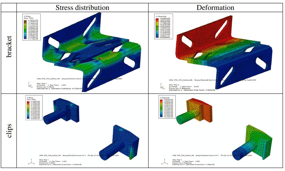
To analysis stress distribution and deflections of the guide rail bracket ABAQUS/CAE 6.6-1 software is selected as a finite element analysis tool. The stress and the deformation distributions are illustrated in Figure 3 for normal use-running condition and load distribution is in the front.
To see the effects of fixing guide rail at the pit in safety device operations, another case is analyzed in this study. As it can be seen from Table 3, the vertical load is carried by the rail itself and partially by the brackets when the guide rail is fixed at the pit and both the stress and dis-placement values are within the permissible limits. For a different case, von Misses stress distribution and displacement of the guide rail brackets and clips for not fixing at the pit situation are shown in Figure 4.
Obtained values of stresses and values of displacements for guide rail brackets and clips are tabulated in Table 3. These results are gained from ABAQUS/CAE software.
As seen from the table, the most important situation for brackets and clips are safety device operations. But the values of stresses and the values of displacements occurred in the guide rail brackets, in this study, are considerable for all load distributions and situations.
The guide rail not fixed at the pit condition is considered and the values of the stresses and displacements are calculated. Table 3 also shows the comparison of stress and displacement values for the fixed and not fixed conditions.
5. Results and Discussions
In this study, elevator guide rail brackets are considered for different loading distributions in different operation situations. Finite element modelling and analyses of the system are managed by using ABAQUS/CAE commercial software. The analyses in the study show that the stress and displacement values occurred in guide rail brackets are considerable but the most critical situations are safety device operations. The results show that fixing the guide rail is very important for guide rail and guide rail brackets. The vertical load is mostly carried by guide rail brackets and stress and displacement values become greater than the permissible limits. The guide rail should be fixed properly with considering the vertical movement allowance during the safety gear operation.
Acknowledgement
This research is a part of work for the project funded by ITU Research Fund: Grand No: 11_06_106 “Investigation of Design Parameters and Analysis of Progressive Safety Gear Blocks”.
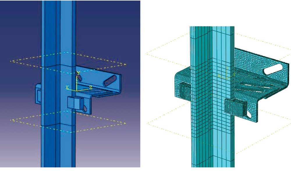
Figure 1. Finite element model of the system 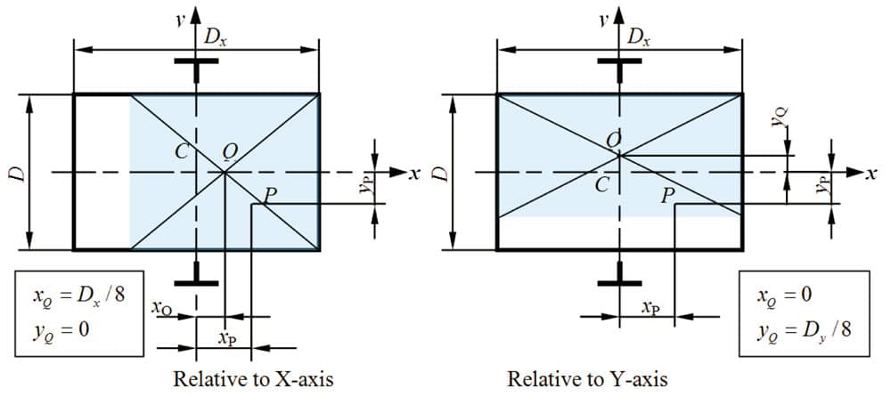
Figure 2. Load distribution in the car and related dimensions 
Figure 3. Stress and displacements on the guide rail bracket and clips 
Table 1. Modelling and design parameters 
Table 2. Material properties and finite element properties 
Table 3. Stress and displacement values for guide rail bracket and clips
References
Day, P. (2000). Transportation Systems in Buildings Guide D, CIBSE, Norwich. Demirsöz, R, Imrak, C.E., Targıt, S. (2005). Finite Element Analysis of Elevator Guide Rails During Safety Gear Operation, Elevator Technology 15, Proc. of ELEVCON’2005, pp.41-50.
Imrak, C.E., Bozdag, E., Sunbuloglu, E., Toprak, T., Targıt, S. (2006). Experimental Stress Analysis of Guide Rails, Elevator Technology 16, Proc. of ELEVCON’2006, pp.111-119.
Imrak, C.E., Bedir, S., Targıt, S. (2008a). Investigation of Stresses on Guide Rails and Safety Gears, Elevator Technology 17, Proc. of ELEVCON ’2008, pp.111-119.
Imrak, C.E., Bedir, S., Kayao˘glu, E. (2008b). Finite Element Modelling & Stress Analysis on Guide Rails During Safety Gear Operation, Symposium in the Mechanics of Slender Structures MoSS 2008, Baltimore, USA.
Janovsky, L. (1999). Elevator Mechanical Design, the third edition, Ellis Horwood Publ., London, 322 pp.
Koç, S. (2009). Elevator Guide Rail Brackets Stress Analysis, MSc. Thesis, ITU, Istanbul.
Moaveni, S. (1999). Finite Element Analysis: Theory and Application with ANSYS, Prentice-Hall, New Jersey.
Targıt, S. (2002). Elevator Guide Rails, Installation and Alignment, Elevator World September 2002, pp.102-105.
Get more of Elevator World. Sign up for our free e-newsletter.

