Determination of Loads Acting on Guide Rail Fixing Under Certain Loading Condition
Oct 1, 2014

by Sühan Atay, Eren Kayaoğlu, Adem Candaş,
C. Erdem İmrak, Sefa Targıt and Yusuf Z. Kocabal
This paper was presented at  Paris 2014, the International Congress on Vertical Transportation Technologies, and first published in IAEE book Elevator Technology 20, edited by A. Lustig. It is a reprint with permission from the International Association of Elevator Engineers
  (website: www.elevcon.com). This paper is an exact reprint and has not been edited by ELEVATOR WORLD.
Abstract
In terms of provide safety and smooth travel, guide rails and their fixing components are essential elements of the complete elevator system. Loads acting on the guide rails and fasteners occur during the elevator car normal travel lead to bending and buckling (or tensile) stresses. In this study, numerical calculations are explained according to EN 81-1 for certain loading conditions. Stress and deformations occur on the fixing components (bolts and T-clips) are examined by experimentally. Finally, the results obtained from numerical calculation and test results are compared and discussed.1.
1. Introduction
Elevator systems are composed of many elements. Rail brackets and steel clips are used for fixing guide rails to shaft wall and provide the linearity of the guide rails. These are the essential elements of a complete rail fastening system. Guide rails are, for safety reasons, the most important element of elevator systems. The basic functions of the guide rails and rail fasteners in the elevator system are to guide the elevator car and counterweight in their vertical travel, to minimize the horizontal movement of the car as much as possible, to prevent tilting of the car due to eccentric load, and also to provide safe stance and to stop the car during safety gear operation activated in case of free falling of the passenger car. Various forces occur during the elevator car travel, safety gear operation, and seismic activities upon on guide rails and rail fasteners. When guide rails are not mounted properly, especially during the operation of the safety brake guide rail brackets would be subjected to excessive loads. These forces on them lead to bending and buckling (or tensile) stresses effecting on fasteners and mounting elements. Review of literature about the topic shows that studies related with stress and deflection analysis of guide rails, brackets and steel T-clips generally remained limited to the computer environment (Atay 2013).
2. Guide Rails, Brackets and Fasteners
In this study, fasteners under certain loading conditions were concerned. Guide rails and complete rail fastening system are shown in Figure 1.
Idea of examining the behaviour of elevator brackets and its connections under static and dynamic loads with an experimental study emerged from knowledge that obtained as a result of experimental stress analysis of elevator guide rails and finite element modelling and simulation studies in the Elevator (Lift) Technologies Laboratory, ITU Faculty of Mechanical Engineering, and an experimental set that is submitted by Dr. Merz from HILTI firm in the comprehensive articles (Merz 2008, 2010).
Bracket connection system will make displacements or relative movements under the loads applied during tests. Loads on rail brackets and its joints that for fixing guide rails to wall of the elevator shaft, studied experimentally. In this case the brackets are mounted with pre-stressed bolts (Figure 3). Wherein by the application of transverse forces between the parts, a μFpre friction force, (Ffric) occurs. The theoretical principles of fasteners are given for making the mechanical joint effective (1).
Ffric = μFpre ≥ F/i or μFpre = c0 F/I (1)
Where i is the number of bolts and c0 = 1.1 – 1.5 is the safety factor against sliding. From this equation, the force necessary to provide the joint can be found.
M12 bolts and T3 T-bolts are suitable for T90 guide rails in accordance to the standards (Imrak and Gerdemeli, 2000).
3. Test Setup
Those parts that make up the basic elements of the elevator system, examination of the behaviour of the different load cases, monitoring and new constructive measures to be taken to investigate an experimental set was designed and installed for the purpose. Experiments to be made by using this experimental set; with the basic elements of the elevator system is aimed to obtain tangible concrete data. For an experimental study on the guide rail brackets and its connections, possibilities within the experimental set system was designed and established with the support and contributions of the sponsor companies. The experimental set, designed, which was tried to have the qualities that will allow for compliance reports and research and investigation to be made more comprehensive in the future on a variety of guide rail brackets and its connections. This experimental set system consists of four main structures. These are carrier structural frame that is used to connect the elements to be tested in experimental studies, hydraulic power unit that provides variable loads to be applied, control-drive unit and sensors. The carrier structural frame is used to connect the experimental elements, which is made of St37 material, is a structure formed by the method of welding using profiles from T90 guide rails. The system designed to simulate elevator car loads applied during operation of an elevator was for the application of tensile and shear loads of a guide rail unit.
A data acquisition and measurement equipment were used during the experimental studies. Test setup was designed for experimental stress analysis of complete guide rail fastening systems, brackets and fasteners were connected to the T90/B guide rails at the test tower in ITU Faculty of Mechanical Engineering (Figure 4). Available sensors and data acquisition system connected to the guide rail fasteners. Real time data were obtained by examining different loading conditions of the elevator test cabin. Tests were carried out in the test tower which is 7.3 m high.
The purpose of the tests were to investigate the forces from the guide rail fasteners and brackets under different loading conditions of elevator cabin and interpret the results as experimentally.
USB sensor interface device is used to transfer data from sensors to the PC environment (DigiVision Software) (Figure 5). It has 16-bit resolution and allows up to 2500 measurements per second.
Load measurement sensors are divided into two categories; these are tension and compression load cell and donut load cell (Figure 6). In this study donut load cells were used in order to investigate the compression loads on bolts.
In the test, 8-person elevator cabin with empty and loaded (100% full) cases were investigated. Steel casting weights, each weighing 17.3 kgs, were used in the elevator cabin frame to ensure empty and full status (Figure 7).
Brackets elements, made of St37 material, and were utilized at the test tower. Test results were taken from the ring type (donut) load cells placed on guide rail fasteners (steel clips) (Figure 8). During test car’s course, the forces applied on the brackets and the bracket joints were observed through donut load cells.
In tests T90/B type standard guide rail was used. Guide rails were fitted to the base with four bearings and there is 2000 mm distance between the guide rail mounting brackets. Different test cases and configurations can be seen on Fig. 9.
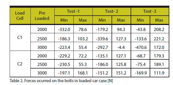
Bolts were fastened by different torques. These torques caused 3 different pre-loading conditions: 2000, 2500, 3000 N. Point zero calibrated in accordance to these pre-loads. Forces below pre-load values are negative and above these values are positive. Results can be found on section in Table 1 and 2.
4. Test Results and Conclusion
The matter of seismic activities on the elevator systems is not a new discussion but it has come into question especially after Van Earthquake 2011 in Turkey. The improved safety aspect must be underlined in respect to structural safety and reliability during seismic activities. So this paper focused on seismic activity loads and their effects on guide rail fasteners. Thus brackets and bolts were subjected to loads similar to the case of seismic activities.
As can be seen in Table 1 and Table 2, maximum load occurred on bolts is -470.6 N at Test-3 in 3000 N pre-load condition from C1 load cell. According to Eq.1 the force to untie this connection must be more than 7549-8088 N due to the standards (BS EN ISO 898-1:1999). Comparison of these two values shows that safety factor is approximately 16.
Acknowledgement
This document is supported by Machinery Promotion Group, Central Anatolian Exporters Union.

Figure 2. Brackets and T-Bolts 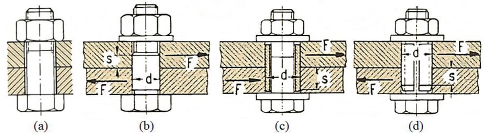
Figure 3. Bolts under transverse loads 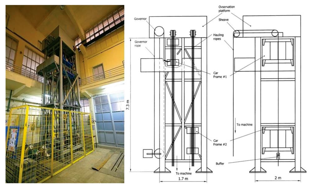
Figure 4. The test tower in ITU Elevator Technology Laboratory 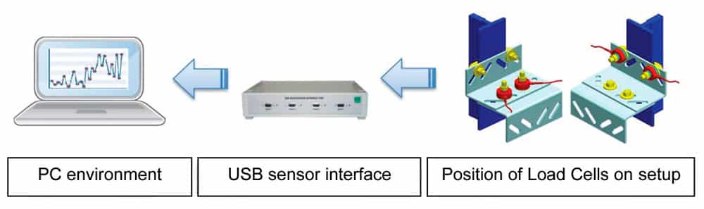
Figure 5. Data acquisition and signal processing system of the test setup 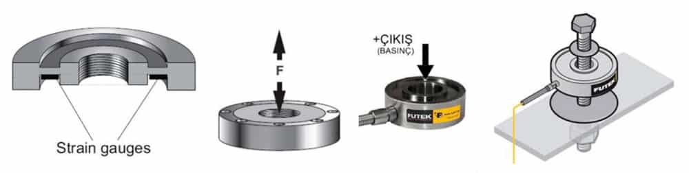
Figure 6. Donut type load cell used in experiments 
Figure 7. Elevator test car loading conditions 
Figure 8. Donut type load cell used in experiments 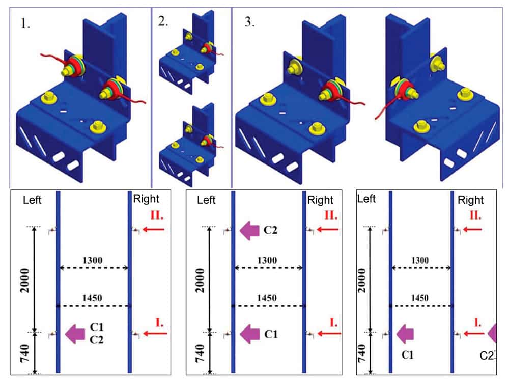
Figure 9. Configurations of 3 different test cases 
Get more of Elevator World. Sign up for our free e-newsletter.


