Development of a Holistic Solution for VVVF Drives
Feb 1, 2018

Several concerns about this industrial norm are investigated.
This paper was presented at  Madrid 2016, the International Congress on Vertical Transportation Technologies, and first published in IAEE book Elevator Technology 21, edited by A. Lustig. It is a reprint with permission from the International Association of Elevator Engineers
  (website: www.elevcon.com).
By Dr. K.M. Tsang, Dr. W.L. Chan and Dr. Albert So
The use of variable-voltage, variable-frequency (VVVF) drives is the industrial norm of the modern elevator industry, irrespective of whether a conventional three-phase induction motor or a permanent-magnet synchronous (PMS) motor is employed. This being the case, several concerns about VVVF drives must be investigated. First, most drives continue to use inefficient braking resistors during the braking process, even though energy-saving regenerative braking devices are gaining popularity. Second, the power quality of most drives is unsatisfactory due to the uncontrolled rectifier at the first stage of the system, calling for the installation of either an active or passive filter. Third, these drives usually cannot tolerate voltage dips during adverse weather conditions or transients of the power transmission system. Fourth, a separate meter must be installed to monitor all parameters related to the power quality. An Innovation Technology Fund (ITF)-funded project was conducted at Hong Kong Polytechnic University to develop a holistic device to tackle all these issues. This article outlines its design and prototype development.
Introduction
Since the late 1980s, VVVF drives have been popularly used for almost all lifts in the world because of their energy efficiency and precise speed control. Scalar and vectored control algorithms (Chan and So 1995, 1996; Ng et al 1997; Kulkarni et al 2000; Kulkarni 2000) have been adopted for good dynamic and transient performance. No matter what the control algorithm is, the basic hardware looks almost the same for all types of elevator drives (Figure 1).
The input converter, a three-phase rectifier, is connected to the power supply from the grid, which converts three-phase AC to a DC bus through an L-C filter to remove ripples. The DC is fed to the three half-bridge inverters, where a three-phase AC of VVVF is used to power the elevator motor. During normal operation, the power flow is from left to right in Figure 1. Under a heavy-loaded down or light-loaded up situation, power is regenerated from the AC motor and fed back to the DC bus through the three-phase inverter. Since the input converter of most installations does not allow electric power to flow back to the grid — i.e., from right to left — a power switch (Td in Figure 1) is used to draw a current through the braking resistor Rd to dissipate the regenerated power. This is called “dynamic braking.” Energy is wasted and the ambient temperature near the drive gets higher, demanding a more powerful ventilating or air-conditioning system to keep the temperature to 40°C or below, as required by the code.
Besides the handling of the regenerated power, there are two more issues with the circuitry. The normal operation of the inverter very much depends on the healthy DC bus with a designated voltage. Suppose there is a sudden drop in voltage with the DC bus: in this case, the operation of the drive would be seriously disturbed, possibly resulting in tripping of the drive. One more issue is that the three-phase converter draws current from the grid intermittently, because current can only get through the diode(s) when the instantaneous three-phase line voltage is higher than the voltage on the DC bus. This characteristic produces a very poor power quality at the grid, which must be addressed.
This project aimed at developing one holistic solution to take care of all three issues and, thus, make a lift system comply with relevant clauses within the energy code. The background is further discussed in the next section before the solution is discussed.
Background Related to Energy Code
It is well known that the lift system may account for 5-15% of all energy consumption of a modern high-rise office building and up to 50% of the public component of a residential counterpart. Hong Kong is the pioneer of energy efficiency of elevator systems being governed. In 1997, a task force was formed by the Electrical & Mechanical Services Department (EMSD) of the Hong Kong Special Administrative Region (HKSAR) government to publish a series of four codes of practices for building services installations, including air-conditioning, lighting, electrical, and lift and escalator.
In 1999, the first energy code for lift and escalator installations was published, with regular updating until 2007. During that period, implementation had been purely on a voluntary basis. By 2009, the HKSAR government intended to make the codes mandatory according to law. In 2012, the Buildings Energy Efficiency Ordinance Cap 610 was enacted. Since then, all newly constructed buildings must ensure that the four key types of building services installations comply with the design standards of the Building Energy Code (BEC, with the full name, “Code of Practice for Energy Efficiency of Building Services Installation”). Up to now, BEC has been published twice, the 2012 version and the 2015 version. In principle, both are similar, except that the requirements stated in BEC 2015 are more stringent. According to BEC 2015, the latest edition, new and renovated lift systems must comply with requirements of energy efficiency and electric power quality, and some relevant issues are listed as follows:
- Clauses 8.4.1 and 8.4.2 set the maximum electrical power (in kW) consumption of a lift, traction and hydraulic, respectively, at rated load and/or at rated speed. This issue must be dealt with by the VVVF drive itself, which is beyond the scope of our design.
- Clause 8.5.1.1 states that the total power factor (TPF) of a lift at the isolator connecting the lift to the building’s electrical-supply circuit should not be less than 0.85 when the lift is carrying a rated load at its rated speed and traveling in an upward direction. This requirement is within our scope.
- Clause 8.6.1 states that when a lift is moving up with rated load at its rated speed, the total harmonic distortion (THD) produced by the motor drive at the isolator connecting the lift to the building’s electrical supply circuit should be limited according to a table. For example, the limit is 35% if the circuit fundamental current is between 40 and 80 A. This is also within our scope.
- Clause 8.7.1 states that metering devices should be provided for the electrical supply circuit for the motor drive of each lift for measurement of voltages (all line-to-line and line-to-neutral), currents (three phase and neutral), TPF, THD, energy consumption (in kWh), active power (in kW) and maximum demand (in kVA). This is also within our scope. At present, in Hong Kong, most new installations are equipped with a passive power filter (L-R-C combination) between the grid supply and input converter to deal with the THD and TPF requirements. Although digital and networked power meters are popularly installed at each major molded-case circuit breaker or fuse switch with, say, a capacity of 200 A or above, inside the main switch room of the building, such practice is still unpopular with lift drives. With the enforcement of BEC 2015, all drives of new installations need to be equipped with a digital meter. As shown in Figure 1, during braking or high-load downward movement, energy is wasted in the resistor Rd as Td is turned on. According to BEC 2015, such “dynamic braking” may not be acceptable under all conditions anymore.
- Clause 8.5.5 states that regenerative braking should be provided for each lift with (a) a rated speed of 3 mps or above, and (b) a rated load of 1000 kg or above, and the power from the regenerative braking should be fed toward the incoming power-supply source. This requirement is dealt with by the project.
Background Related to Voltage Dip
Voltage dips caused by adverse weather conditions may be unavoidable. The term “voltage dip” is widely used in Europe, while “voltage sag” is used by the trade in the U.S. (ELEVATOR WORLD, February 2015). The authors were first inspired to look into this issue in 2004 after a serious voltage dip (sag) caused by a heavy thunderstorm in Hong Kong led to more than 50 lifts being suddenly tripped, trapping quite a number of passengers (So and Chan, 2015). Normally, when one lift fails to operate, and passengers are trapped, the building management calls upon the maintenance contractor first. And, if there is potential passenger injury, help from the police and then the fire department is sought. This practice is perhaps usual anywhere around the world. But, if we think about the situation when hundreds of lifts are tripped at the same time due to an electric power problem — voltage dips and blackouts being some possible causes to consider — is it likely that adequate support from both the maintenance contractors and the fire department is available to rescue thousands of trapped passengers? Furthermore, after a series of voltage-dip events, followed by immediate lift stoppages somewhere along the hoistway, in Hong Kong, from 2004 to 2006, the society started to debate who should bear the responsibility: the electric utility, the elevator manufacturer and/or the maintenance contractor?
One of the best references to the issue of electric power quality is IEEE Standard 1159-2009 on the recommended practice for monitoring electric power quality. The issue of voltage dip, of course, falls within the category of electric power quality. A voltage dip is not considered a power failure or interruption, and, most of the time, lasts no more than 0.2 s. before the normal power supply is restored, although the formal definition allows a prolonged existence of up to 0.5 s. for an instantaneous one. There could be many causes of voltage-dip events, which are mainly associated with bad weather conditions. During a thunderstorm, lightning often hits the overhead transmission lines, which are responsible for the transmission of electric power from the generating plant to substations. Such overhead lines are usually found in the suburbs, across mountain ridges or on plains, where they are the highest objects adjacent to their neighborhood. Although the tip of transmission towers is connected by an earthed shield or guarded wire for protection, while the transmission voltage, say, at 400-800 kV, is a bit closer to the voltage of the lightning strikes, there are still chances of the overhead lines being hit. After the lightning hits the overhead line, it will often continue to penetrate through the air below and finish up hitting the ground. During its passage, the overhead line is instantaneously shorted to earth, causing a voltage-dip event.
In Hong Kong, in relation to lifts and escalators, a voltage dip is defined as a reduction in supply voltage to 60% of the rated value, with a duration of up to 0.2 s. In 2005, EMSD of the HKSAR government issued a replaced clause (8.4.1.2) in the Code of Practice on the Design and Construction of Lifts and Escalators (2000 Edition). Under the clause, the braking system of an escalator shall operate automatically (a) in the event of loss of the voltage supply, (b) in the event of loss of the voltage supply to the control circuits or (c) for an escalator installation equipped with protection devices to enable it to sustain operation (“ride-through”) during power-supply voltage dips, (i) at the lapse of 0.2 s. of a continuous-supply voltage dip of more than 10% of the supply voltage or (ii) at a voltage dip exceeding 60% of the supply voltage or (iii) at the failure of the protection device. Although such ride-through devices are allowed to be used on escalators, the HKSAR government is still very conservative on the application of the ride-through concept on lifts. This is also within the scope of the project.
A Study on Regenerative Braking
To include regenerative braking in the holistic solution, the voltage waveform on the DC bus was monitored and recorded under a no-loaded up or full-loaded down condition of a lift. The result is shown in Figure 2(a) with two zoomed windows shown in Figure 2(b) and Figure 2(c). It can be seen that the DC voltage stays at a nominal value when the car is not in operation, while it starts to drop under a loaded up journey. A loaded down journey causes the DC voltage to rise beyond the normal value. Once the voltage reaches an upper limit, Td is turned on, and the energy is dissipated in the resistor Rd, thus causing a drop in voltage. When the voltage drops to a certain lower limit, Td is turned off, and the voltage rises again. Regenerative braking should perform in a similar way. However, the exact upper and lower limits of switching in and out vary by drive, and, therefore, an optimal regenerative braking setting is difficult to determine. Moreover, the supply voltage of the grid also varies from day to night. It is unreliable and sometimes unstable to set fixed upper and lower limits for all situations, resulting in a non-optimal control. In the holistic solution, a new approach is adopted so that control does not solely rely on voltage fluctuation.
Rationale of Development of the Holistic Solution
At present, there are products on the market that tackle each of the above requirements, i.e., regenerative-braking devices, active power filters, comprehensive power meters, etc. They are, first, independent of one another; second, their technical details are treated as commercial secrets; and, third, they are not interoperable, thus making full compliance with the BEC by existing lifts very expensive. In our design, all of them have been integrated into a single device that arrives at a cost-effective solution. Technically, four issues have been addressed. First, as mentioned above, one device will be enough in the future, which will greatly reduce the costs of hardware, software, installation and maintenance. Second, the new device will be compatible with all standard lift drives installed after the 1990s that are equipped with converters, DC buses and inverters. Manufacturers of the solution can then be independent of lift manufacturers. That is also one way to lower the cost for the benefit of lift owners. Third, at present, all functions mentioned above need precise and accurate setting of parameters inside the devices. If devices are incompatible with one another, it is difficult to arrive at the optimal set of control parameters to be tuned.
Often, the limited skill of technicians may further hinder the optimal operation of these devices. With one holistic solution, parameter settings can either be fully automatic or user friendly. In particular, those related to the DC bus need accurate tuning when regenerative braking is effective and when stabilization is needed. Our new control algorithms built inside greatly reduce manpower to adjust the settings. Finally, the way to practically benefit lift owners is to lower the cost. It is the goal of the research team to make sure the total hardware production cost of each final device will be kept below US$2,000.
The Hardware
Figure 3 shows the overall design structure of hardware. The inverter-connected DC bus is connected to a newly designed bidirectional DC/DC converter, which is the key element of the whole design. This converter serves two purposes. First, the voltage at the DC bus is not fixed. For some lifts, a transformer is used to step down the voltage of the grid, and, hence, the DC bus voltage is reduced accordingly. Second, by using the DC/DC converter, it is possible to raise the voltage across the capacitor to a much higher level; say, close to 1,000 V. Then, the efficiency of power flow will be much higher. The other side of the DC/DC converter is at a relatively high voltage (600-1,200 V), which is stabilized by a capacitor of around 2,000 uF. Such a capacitor-connected DC bus is connected to a newly designed bidirectional three-phase active power filter, the structure of which is shown in Figure 4. When the voltage across the capacitor reaches a high value — 110% or more above the rated value — power is fed from the capacitor to the three-phase grid via the bidirectional active power filter. At the same time, power is drawn by the DC/DC converter from the inverter-connected DC bus to the grid via the capacitor-connected DC bus and then the bidirectional power active filter. In other words, the responsibility of drawing power from the inverter-connected DC bus to the capacitor lies with the DC/DC converter, thus saving some control activities of the bidirectional active power filter.
During normal operation, the bidirectional active power filter draws power from the three-phase grid to keep the capacitor properly charged. Throughout this charging process, the active power filter behaves as an active filter, correcting the TPF and THD at the three-phase supply to the required standards. The DC/DC converter receives signals from the newly developed online AC power analyzer, which is also a component within the holistic solution, developed on the ADE7880 polyphase multifunction energy metering IC with harmonics monitoring.
For regenerative braking, the DC/DC converter can then confirm this by two simultaneous means: first, checking whether the voltage of the inverter-connected DC bus is beyond, say, 110% of the rated value, and, second, more accurately checking the power drawn from the three-phase grid by the uncontrolled rectifier with the help of the power analyzer, which also continuously monitors other parameters, such as voltage, current, TPF, apparent power and harmonics, etc. to fulfill the requirements of the BEC. Once regenerative braking is confirmed, the DC/DC converter will extract power from the inverter-connected DC bus to boost the voltage of the capacitor to more than 110% of the rated value, then the bidirectional active power filter, to further extract power back to the three-phase grid.
Since regenerative braking is now confirmed by two different means, the decisionmaking process is more reliable and secure, compared with the conventional way of checking the DC bus voltage alone. When the lift is not in operation, but the supply voltage from the grid rises, the DC/DC converter does not function, even though the voltage on the inverter-connected DC bus rises, because the power analyzer recognizes the abnormally high grid voltage is not a regenerative braking process.
For voltage-dip ride-through, the power analyzer recognizes a voltage-dip event and instructs the DC/DC converter to temporarily retrieve power from the capacitor to feed the inverter-connected DC bus for the short period of time (not longer than 0.2 s.), thus avoiding tripping of the motor drive. It should be noted that the energy stored inside the 2,000-uF capacitor is not enough to support the inverter-connected DC bus to withstand a duration of 0.2 s. under a fully loaded up condition. It is expected that voltage dip with the three-phase supply is down only to 40% of the rated value, and the bidirectional active power filter can still charge the capacitor continuously as the DC/DC converter draws power out of it.
IGBTs versus MOSFETs
In the bidirectional active power filter, silicon carbide (SiC) MOSFETs are used instead of insulated-gate bipolar transistors (IGBT), although in conventional inverters, IGBTs are extensively used. There are two reasons. First, the conduction losses of MOSFETs are lower than those of IGBTs (Figure 5). At the same current, VDS across the MOSFET is much lower than the VCE of the IGBT; thus, lower losses. Second, the allowable switching frequency of MOSFETs is much higher than that of IGBTs. A higher switching frequency of operation of the filter means that passive components, including inductors and capacitors, can be downsized, which is beneficial to manufacturing and installation.
Conclusion
The rationale of the project of developing a holistic solution for lift drives has been discussed, and the hardware design of the solution consisting of newly developed components, including DC/DC converter and bidirectional active power filter (which serves two purposes, as a filter and a regenerative device), has been discussed. It is hoped that, in the near future, such a device could be available with a reasonable price for all lift owners.
Acknowledgement
The project was funded by Innovation and Technology Fund (ITS/026/14FP) of the HKSAR government and was conducted at Hong Kong Polytechnic University.
-
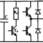
- Figure 1: Typical hardware of a modern VVVF elevator drive
-
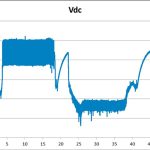
- Figure 2(a): Voltage waveform on DC bus
-
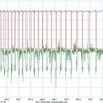
- Figure 2(b): Zoomed voltage waveform during no-loaded up or full-loaded down condition
-
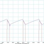
- Figure 2(c): Further zoomed voltage waveform
-
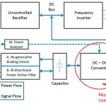
- Figure 3: Hardware configuration of the holistic solution
-
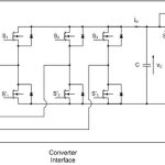
- Figure 4: Hardware configuration of the bidirectional active power filter and the capacitor
-
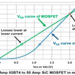
- Figure 5: Losses of SiC MOSFETs versus IGBTs

Get more of Elevator World. Sign up for our free e-newsletter.


