Digital and Analog Troubleshooting
Feb 1, 2016

Tools and techniques to help the technician find faults in circuits, signals and drives
Physical quantities can be represented by numerical values in either analog or digital. The analog method may be visualized as a simple sliding scale in which the numerical values can be expressed as being located at any point along a continuum. They can be zero or have a positive or negative value that is a whole integer or fractional amount extending from either side of zero to infinity.
In contrast, in the digital protocol, the numerical value of a physical quantity is represented by quantized steps having only predetermined discrete levels. Most digital systems currently in use are binary, although a base 10, base 16 or any other amount can be used. The binary system is well suited to electronic applications, because 1 and 0 can be represented by presence or absence of a voltage or by two separate voltages – one high and one low. To implement a base-10 logic, the number of different voltages would be unwieldy and error prone. The tradeoff is that in the binary system, more digits are needed to represent a given value, but through the miracle of electronic number crunching, that is not a problem.
Learning Objectives
After reading this article, you should have learned about:
♦ Correct high and low voltages of TTL and CMOS logic circuits
♦ Characteristics of a clock signal
♦ Types of digital test equipment
♦ Troubleshooting methods for digital and analog circuits
♦ How VFDs operate and how to safely adjust them
Of course, our real world, outside of the quantum domain, is analog, rather than digital. Therefore, digital equipment has inputs that will accept analog signals. After attenuation or amplification, this energy is translated into streams of digital pulses by means of a fairly simple device known as an analog-to-digital converter. Similarly, the output is usually required to be analog (for example, to drive a speaker), so a digital-to-analog converter is needed.
The first digital machines were built using mechanical switches and relays. Heat, size, reliability and cost placed upper limits on this technology. Advances began in the 1940s with the introduction of the solid-state diode. Silent transistors and integrated circuits rapidly replaced rows of clacking relays. Much lower operating voltages and reduced power consumption, along with component miniaturization, now characterize electronic communication and control circuitry found in telephone central offices, elevator machine rooms and throughout industrial facilities.
Transistor-transistor logic (TTL) is typically powered at +5 V. If 5.25 V is exceeded, the device may be subject to damage. When a TTL NOR gate or other device is at a potential from 0 to +0.8 V, the gate will respond to a logic-high input. If it is an inverting NOR gate, the output will be logic low. When +2 to +5 V is applied at the input terminals, the gate responds to its former logic-low status. Logic high is the response if, again, the device is an inverting NOR gate.
Complementary metal-oxide semiconductor (CMOS) technology is widely used at present. Unlike TTL, the supply voltage may be from +3 to +15. The high and low levels are figured differently from the way they are in TTL. They are set at a fraction of the supply voltage. If the supply voltage is between 3 and 10 V, the logic high level is greater than 7/10 of the supply voltage with a tolerance of 0.5 V. The logic-low level is a voltage less than 3/10 of the supply voltage, with the same tolerance. If, however, the supply voltage is between 10 and 18 V, the logic-high and logic-low levels are the same fractions of the supply voltage. However, the tolerances in both instances rise to 1 V.
These metrics may appear belabored, but the fact is that in troubleshooting digital circuits, the tolerances are very important. If operation is faulty, ascertain whether these voltages are within the above specifications. Digital memory is built of basic latches, which may be configured from cross-connected NOR gates. These are often referred to as “flip-flops,” but this is a misnomer, since a latch is an asynchronous device, whereas a flip-flop is clocked and operates in step with clock pulses. The latch, in contrast, is an asynchronous device.
Synchronous digital devices require clock circuits, which can fail. The clock signal is typically a square wave that alternates between high and low levels with a 50% duty cycle. Integrated circuits (ICs) that are at all complex rely upon a clock signal that synchronizes the overall operation. Sometimes, more than one clock signal is required. Clock signals are generally single phase, meaning that they propagate over one wire, but multiphase clock signals have been used. Frequency may vary, and this is not necessarily detrimental. A clock multiplier boosts the operating speed for the benefit of a microprocessor so it can run at a faster rate than that of other circuitry. Newer computers boast ever-faster clock speeds, which improves performance.
Troubleshooting Tools
To perform digital troubleshooting, the tools of the trade are a good high-impedance multimeter, an oscilloscope, a logic probe, a logic pulser and a digital current tracer. These will be discussed in the following sections.
Multimeter
The multimeter is the most basic of the electronic technician’s diagnostic tools. In the ohms mode, the multimeter can detect solder bridges between adjacent circuit-board traces. Cold solder joints, bad ribbon connectors and so on are quickly revealed. It is also good for checking diodes and electrolytic capacitors as found in the power supply. In the volts mode, a good multimeter is excellent for quickly checking the analog aspect of a variable-frequency drive (VFD). The three-phase power supply can be checked for equal voltages between legs and between each phase and ground. The same measurements can be taken at the motor terminals. The DC bus must yield readings within specifications. In the AC volts mode, harmful ripple can be detected. Powered down and with stored voltages bled out, faulty diodes and electrolytic capacitors can be isolated, and one of these is likely to be the miscreant. When it comes to digital work, the multimeter in the DC volts mode can be used to determine whether supply, logic-low and logic-high voltages are reasonable.
It is to be emphasized that any voltage measurements must be made with a high-impedance instrument so as to avoid loading the device or circuit under test. If such loading takes place, the device(s) can be damaged or at the very least the measurement will be invalid. A cheap US$10 meter from a big-box store may be satisfactory for home wiring jobs, but for digital diagnostic work, a high-end multimeter with advanced features is needed. Expect to pay close to US$500.
Oscilloscope
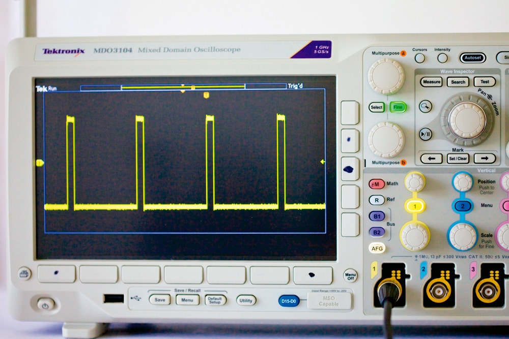
The mixed-signal oscilloscope (MSO) is an excellent instrument that makes easy work of many previously difficult digital troubleshooting problems. The operative concept is that, very often, a faulty digital waveform such as a runt (pulse of insufficient amplitude) is triggered by an anomaly in the analog section. The MSO is capable of showing analog and digital waveforms simultaneously and temporally correlated (with the same X axis), which is also an easy job with the right tool.
Logic Probe
The logic probe is excellent for moving rapidly among inputs and outputs to find out if the logic state is high, low or not present. It consists of a compact body with a conductive point at one end. There are two leads, one red and one black. Alligator clips permit the black lead to connect to the circuit ground or negative side of the power supply. The red lead should be attached to the power supply’s positive rail or to any conveniently located equivalent terminal.
A slide switch on the body permits the logic probe to be set up for TTL or CMOS work, as desired. Consult the manufacturer’s directions (available online) to interpret LED and/or audible indicators. Since it is a high-impedance device, the probe can be touched to nearly any pin or circuit node without fear of damaging the instrument or circuit under test. Since the logic probe is powered from the board through the red and black leads, no battery is required.
Logic Pulser
A common situation is for the circuit under test to be connected to a functioning upstream stage. If this is the case, it is a simple matter to touch the logic probe to the various input and output pins and external circuit test points to see if there is logic high or logic low present at that location. However, sometimes, when no high or low logic is observed, the troubleshooter will want to inject a known good pulse at an IC input or circuit terminal. This is done by means of a logic pulser.
The logic pulser looks like the logic probe. It has an instrument body with a pointed conductive probe tip and red and black leads with alligator clips. As with the logic probe, the black lead is connected to the chassis or circuit ground, and the red lead is connected to the positive rail.
Digital Current Tracer
For successful troubleshooting of digital equipment, the digital current tracer, while less frequently used, is quite valuable in certain situations. Superficially, it resembles the digital logic probe and digital pulser, but the inner workings are totally different. While the logic probe and pulser have conductive needle-point electrodes that are simply touched to digital outputs, the digital current tracer has a magnetic pickup head. It is sensitive to the magnetic field that surrounds a conductor or trace through which current is flowing. This works whether or not the wire is insulated.
To get a good reading, it is necessary to hold the digital current tracer vertically above the conductor. Additionally, the tip of the current tracer has a dot that must be aligned with the direction of current flow. An indicator lamp located at the probe tip varies in brightness in response to the amount of current. It is sensitive over a wide range, 1 mA to 1 amp. There is a control to adjust sensitivity. To locate a current source or sink, simply move the digital current tracer along the current path, watching for changes in lamp brightness.
Using the digital current tracer, the technician has the ability to detect a fault within a microchip, but where the instrument really excels is in isolating a nearly invisible solder bridge between adjacent traces, or a cold solder joint that disrupts the flow of electrons. Faults like these, once located, can be corrected and operation restored without resorting to a massive replacement of semiconducting devices.
Troubleshooting Techniques
Besides using the digital troubleshooting tools described above, there are some other procedures that are effective in identifying failed circuits and components. The following comments are applicable to both digital and analog problems.
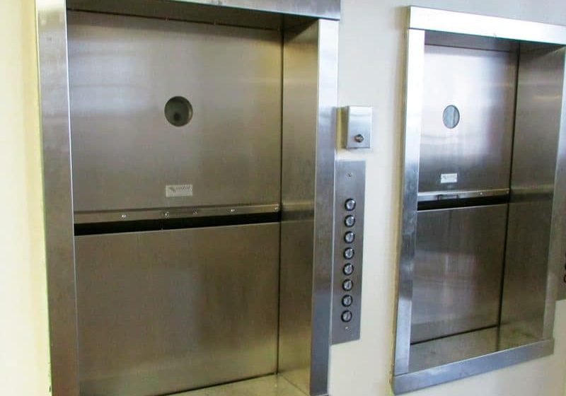
Often, a piece of electronic equipment contains parallel – partly or wholly identical – subsystems. An example would be a bank of elevators or a single elevator that serves multiple floors. The door sensors and controls are usually substantially identical. In such instances, parts may be swapped to see if the fault moves.
Another example is in stereo sound equipment. Components such as speakers or cables from final amplifiers to speakers can be switched to see if operation is affected. In instances like these, the formerly failed system will function normally, and the formerly good system will stop working. Similarly, if there are two separate identical items, it may be possible to switch components as a diagnostic procedure. The viability of this technique has a lot to do with the physical difficulty of making the change. Sometimes, it is more prudent to use more passive techniques, such as monitoring operation with a multimeter, one or more clamp-on ammeters (sometimes using the “Hold” feature, for example, to preserve a record of current draw in three-phase legs over a period of hours).
A lot can be learned by observing the methods of TV repair technicians, because this is a very extensive and well-documented field. A persistent problem that arises in all sorts of equipment, digital as well as analog, is intermittent operation. This can be difficult to diagnose in terms of isolating the defective component, because the fault has a way of disappearing precisely when repair is being attempted. The trouble, since it may be heat or vibration sensitive, tends to come and go. Sometimes, there is an invisible crack in a printed circuit board or component such as a wire-wound resistor that will open and close in response to changing temperature. TV technicians often heat or cool components one at a time to see if the fault will surface or go away. This can be done using a soldering iron held some distance above a microchip so as to heat it just enough to bring out the fault but not enough to damage it if it proves not to be faulty. Alternatively, there is commercially available “component chiller” in a spray can. If the spray is directed on the suspected culprit, it will be suddenly cooled, the fault disappearing. (This technique is good for diagnosis only and is not effective as a repair. Component chiller is also used to precool semiconductors with short leads so they won’t be damaged during soldering.)
Another diagnostic technique that can be used to good effect is to remove questionable components that are not essential for the correct operation of the system as a whole. For example, several telephones may be connected to jacks arranged in star topology. It happens that if one of the phones has an internal line-to-line short circuit, it will drag down the system as a whole. Specifically, there will be no dial tone. Phones can be disconnected one at a time to see if operation is restored. The entire installation can be tested by disconnecting one wire of each pair in succession at the source. A similar technique can be used for ground-fault circuit interrupters in a premises branch circuit or individual computers connected to an Ethernet hub, switch or router via Category 5e cabling or other media.
A final lesson we can learn from the TV service technician is how to perform a signal-tracing operation. A radio-frequency, intermediate-frequency, or audio, video or composite signal derived from a signal generator is injected at the input of an appropriate stage. Then, oscilloscope readings are taken at successive outputs, watching for distortion or absence of the signal. Service schematics characteristically contain graphics at selected locations in the depicted circuitry, showing how a normal display should appear. With this information in hand, the next step is to zero in on the defective component.
Modern Technology
Solid-state electronic AC motor drives, in conjunction with three-phase induction motors, have largely replaced old DC motors in elevator machine rooms. DC motors are simple in construction and can easily be reversed, as is required for elevator operation, merely by reversing the polarity of the two-wire electrical supply. Moreover (and also required for elevator operation), the motor’s speed can be easily and smoothly changed by adjusting the current through the field windings. All of this takes place without resorting to an expensive gearbox, which could lead to extensive downtime upon failure.
The weak link in this chain was the commutator-brush assembly. Because of inevitable arcing and mechanical wear due to friction with the commutator, the brushes always had a finite service life, and although changing them was not a difficult job, it was nevertheless something that had to be done. If this did not always happen on time, the commutator could be damaged, requiring a far more time-consuming repair.
The direction could be reversed, but speed could not readily be regulated in early three-phase induction motors, and for many decades, DC motors drove most elevators, even though AC had to be rectified to power them. All this changed abruptly in the 1960s with the introduction of the variable-frequency drive (VFD). Also called “adjustable-speed drive,” the terminology can refer to the electronic drive plus motor, or to the drive alone.
Basic operation is simple and usually takes place within a convection or fan-cooled enclosure. The incoming three-phase AC power is rectified and filtered using standard diodes and electrolytic capacitors. The reasonably ripple-free power moves via a three-conductor DC bus to an inverter section where an AC feed is synthesized and subsequently fed through appropriately sized conductors to the motor. The unique waveform of the VFD’s output makes the motor’s range of torques and speeds possible.
If we attempt to adjust the speed of an AC motor by varying the voltage applied to the stator, rotor rpm can be reduced somewhat, but this method is unsatisfactory, because the slower speed is accompanied by great heat rise, since the motor is, in effect, being overloaded when operated below rated voltage. The VFD output, rather than a sine wave of varying amplitude, consists of a series of square waves. The pulse widths may be made to vary, comprising different duty cycles. By narrowing the pulse, the motor can be slowed without harmful heat rise and subject only to reduced rpm of a cooling fan that may be attached to the shaft. Compensatory cooling can be accomplished by other means if needed.
The VFD’s inverter section is, of necessity, connected to the elevator’s motion controller with a human interface, door sensors, fire-alarm interconnect, etc.
Learning-Reinforcement Questions
Use the below learning-reinforcement questions to study for the Continuing Education Assessment Exam available online at www.elevatorbooks.com or on p. 129 of this issue.
♦ What are the operating voltages for TTL and CMOS logic?
♦ Is it always harmful if a clock signal frequency varies? Why or why not?
♦ What are the principle sections of a VFD?
♦ How does an MSO oscilloscope reveal defective sections of a VFD?
♦ What are the most-used digital troubleshooting tools?
Get more of Elevator World. Sign up for our free e-newsletter.


