Divider Beam Design as Part of the Standard Elevator Design
May 1, 2024
A new method for installing these as part of the elevator installation process and its benefits
This paper was presented at Elevcon 2023 in Prague, Czech Republic.
Key Words: Elevator group configurations, divider beam, modular system, design standard, quality control, process standard, design report, hoistway, accident prevention, time saving
Abstract
Divider beams can create headaches for project managers who must provide separation walls in a hoistway that should host two or more elevators. To avoid accidents during the handling and welding of heavy steel material, the installation of the beams is often passed to the general contractor or a subcontractor. Involving a third party requires design drawings, a bidding process, coordination, inspection for acceptance and, finally, the complaint procedure.
This paper introduces a new design method for installing divider beams as part of the elevator installation process and discusses the multiple benefits of this innovative solution.
1. Introduction
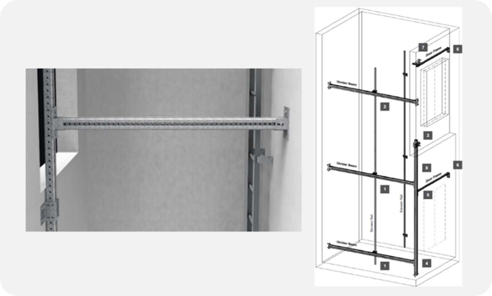
It is common practice that elevator shafts for group configurations (duplex, triplex, etc.) be constructed by the general contractor without partition walls (Figure 1). The front wall of the hoistway is often left completely open. This reduces concrete construction costs and eliminates the risk of complaints based on shaft evaluation and any subsequent corrective work that would need to be carried out. It also provides additional flexibility for the design of the elevator system, which is often detailed only after construction has started.
In this case, the elevator installer will use so-called divider beams to fasten the guide rails. The design and procurement of the divider beams, which are typically made from steel, usually take place locally. This task, including installation, is generally given to a local steelwork company. In some countries, it is standard that the lift company requires that the work be carried out as part of the hoistway construction. It is then carried out under the responsibility of the general contractor.
The design and construction of the divider beam influence the ride comfort of the elevator, particularly on high-performance models. In case of emergency braking in which the safety elements are deployed, divider beams that are improperly installed can lead to the safety device losing sufficient contact with the guide rails, something that can have fatal results. To ensure that the safety device functions properly, there are strict requirements made regarding the maximum horizontal displacement of the system consisting of guide rails and divider beam. For high-performance systems, these requirements are defined to ensure ride comfort (vibration and noise development in the cabin, lobby and adjoining rooms).
The local definition and installation of the divider beam leads to the definition of a large variety of solutions that mainly avoid quality inspections and controlling by the elevator manufacturer in terms of central design and execution. As the system consisting of divider beam and guide rails has a significant influence on the elevator’s safety and ride comfort, a central, specific solution for the divider beams would be very welcome (Merz, 2010).
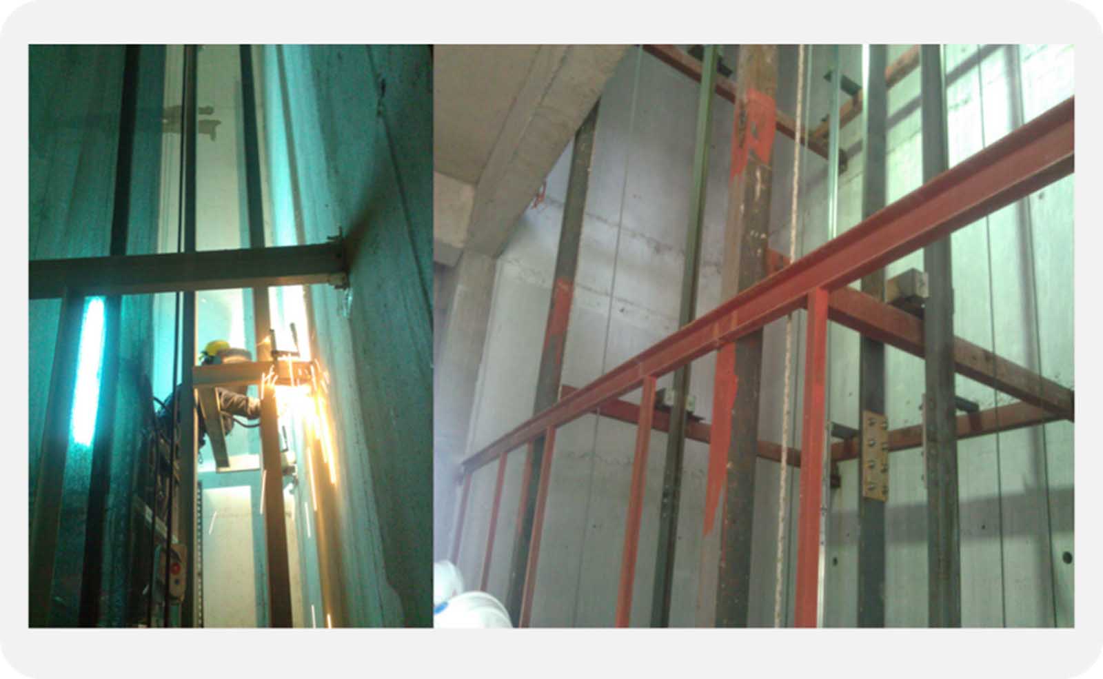
In creating the divider beams, the steel construction often prescribes massive I-beams that have had anchor plates welded to them in the workshop and which then have to be fastened to the shaft wall with anchors right on the construction site. The solution chosen, particularly in seismic conditions, is to set anchor plates in concrete to which the I-beams are welded during installation. Moving massive steel beams in a cramped hoistway environment requires heavy lifting equipment while the welding work can generate sparks. The installation of the divider beams is generally carried out separately, before the assembly of the elevator system, and is concluded before work begins on installing the elevator. Due to the risk of accidents when handling massive steel beams and the fire risk associated with welding sparks, installation of the divider beams is preferably given to a subcontractor (Figure 2).
The effort required to select, hire and instruct a subcontractor in terms of the correct installation of the divider beam is significant. Nonetheless, there is still a risk that there may be complaints, which require reworking, once the hoistway has been officially evaluated. The necessary timeframe required for this advance work reduces the amount of time given to put the elevator system into place. It could also lead to a delay in the elevator system being handed over to the general contractor.
If the divider beams have been installed and approved by the elevator company, connecting the rail bracket can prove problematic. Fastening holes generally have to be drilled on-site; preinstalled fastening holes must often be expanded. In certain cases, the rail bracket can also be welded to the divider beams. Due to the risks associated with this work, no other persons may work in the hoistway during this time, and fire protection must be ensured.
The associated risk of accidents should be avoided, and the time required to perform the related tasks is significant.
Quality assurance during installation and during the elevator company’s acceptance process, once the divider beams have been installed, is quite demanding and difficult to achieve.
2. Modular System for Building Supporting Structures
Standardized modular systems have been used for some time to create supporting structures for fastening and laying out all types of supply lines in installation work in the construction of buildings, facilities and both on- and offshore platforms. These systems have been extended to build platforms for positioning machines and equipment, walkways, footpaths, etc. (Merz, 2014).
Special profiles and connectors have been developed to allow modular systems to be suitable for use in the construction of divider beams. The design is performed with manufacturer-specific design software that monitors the force loads of the entire design and also determines the eventual deformation of the beams.
In elevator model design, modular systems can be integrated as a standard solution so that a centrally defined quality of divider beam design is achieved. With the design of the elevator system, the process of installing modular divider beams, consisting of standard components, can also be centrally defined. This allows for central control of the work quality. If the supplier of the modular system is able to supply the system worldwide, globally uniform divider beam quality can be realized (Merz, 2010).
As modular systems generally consist of much lighter components compared to standard steel beams, the entire installation of the elevator group configuration can be redefined on location. The risk of accidents during installation can be reduced or even eliminated.
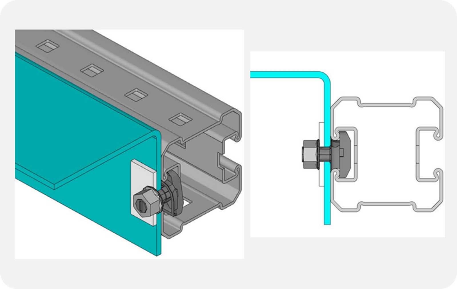
The modular system shown here consists of particularly rigidly designed, hot-dip galvanized steel girders, which, due to the special profile, support a very flexible connection of attachments irrespective of manufacturer. Toothed C-profiles are integrated in both sides of the girder profile (Figure 3). This supports the usage of T-hammerhead bolts for fastening the rail brackets. The T-hammerhead bolts can be moved independently in the C-profile, on both sides, for horizontal positioning of the rail brackets, allowing simplified alignment of the guide rails. In addition to the frictional connection during bolt fastening, the internal teeth shape a form fit that supports the stability of the connection. Drilling fastening holes or welding on the construction site is therefore no longer necessary (Merz, 2014).
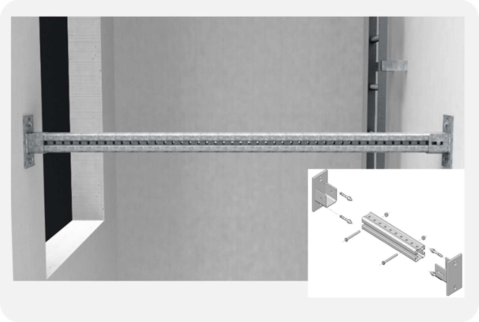
The beams are fastened in special wall connectors having a U-shaped opening. The wall connectors can be anchored to the walls independent of the beam using an anchoring system similar to that which anchors the rail brackets to the shaft walls (Figure 4). Mechanical or chemical anchors, as well as cast-into-concrete anchor channels, can be used (Merz, 2018).
During installation, the preliminary work involved in fastening the wall brackets to the wall includes usage and handling of compact components of low weight, which can easily be positioned and anchored by one person. Laser positioning systems are particularly well-suited for use in positioning the anchoring holes. The actual divider beam is placed in the U-shaped opening once both wall brackets have been anchored.
The divider beam has modest weight (9 kg per meter) when compared to standard steel beams, which are heavier by a factor of 2-to-3 and will therefore be heavier and more difficult to handle in narrow shafts. The divider beam can be moved into the hoistway and then placed in the wall bracket without any special lifting or hoisting devices (Figure 5). The wall bracket design ensures that the divider beams are secured against dropping or falling without any further arrangements or precautions.
After correct horizontal positioning, which can also be used to align the guide rails, the divider beam is clamped to the wall connector’s U-profile with through-bolts. Installation of this type of divider beam can be safely performed by a single person in less than 30 min.
Simple installation requires only a few concise steps and can be well documented in a standard process flow that can be made available to installers worldwide via a centralized documentation system. This supports central quality assurance for a uniform worldwide process for installing divider beams.
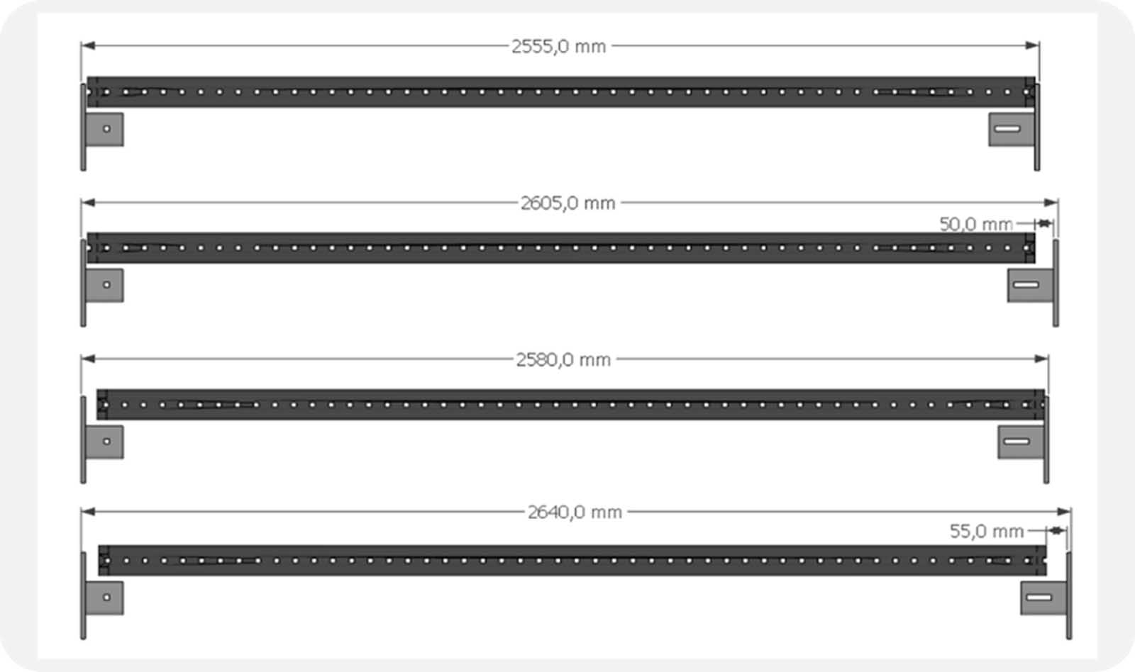
In terms of length and perforation, both wall brackets have been designed to support specification-conforming fastening in conjunction with the hole pattern in the divider beams, even if the shaft depth includes structural tolerances. The system can bridge shaft-depth deviations up to +/- 40 mm, allowing for all divider beams to be delivered to the construction site at a uniform length and doing away with the need for subsequent cutting to size (Figure 6).
3. Technical Design of the Divider Beams
The technical design of the divider beam is supported by a manufacturer-specific calculation software, which is based on the high-performance RSTAB statics program. In order to evaluate the load resistances and performance behavior of the overall concept, Finite Element Analyses of mechanical components are made based on ANSYS 2020 software during the product development process. The design software has been certified by TÜV SÜD.
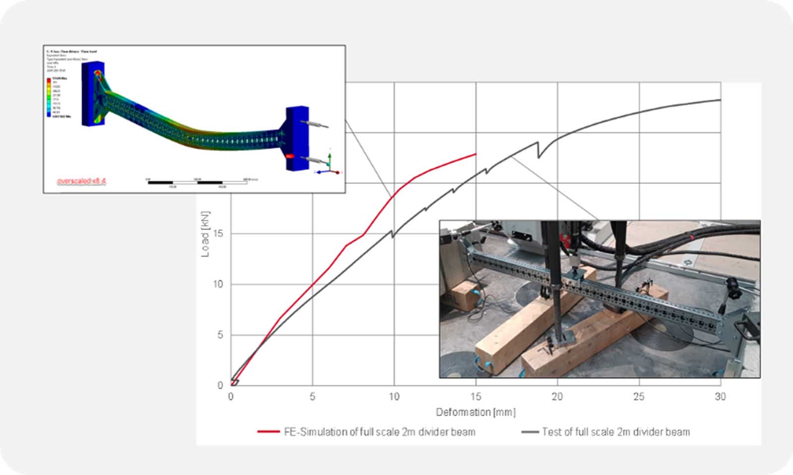
Numerical calculations and practical testing were carried out to calibrate the FE-Model and to determine technical data for all components in verification with physical testing. Figure 7 shows one example of a like-to-like comparison between the practical testing and the numerical simulation of a full-scale 2-m-long divider beam set. The stress distributions in the components and in the overall model were determined and documented in detail. For the case shown (Figure 7), the following setup was used: Material model of S350 for the girder and S355 for the base connectors with around 93,000 multizone hex elements and more than 608,000 nodes. Ultimately, all the evidence and extensive data of the numerical simulations is fed into the calculation software to serve as a basis for the technical design.
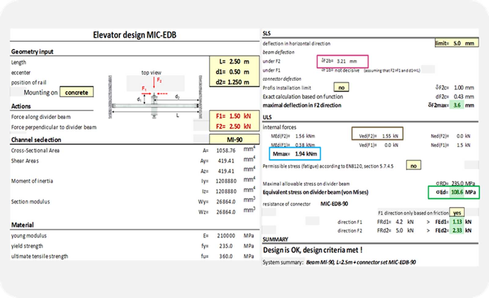
The calculation software creates a comprehensive report on the system’s design. The input data relating to the forces acting on the guide rails is documented, as is the geometric positioning of the guide rails by means of the rail brackets on the divider beam. This is supported by a schematic sketch of the divider beam. The design process results in the suggestion of a specific beam profile and a suitable wall bracket. Their capacity rate is also documented as it relates to the stresses in the components. Additionally, the deflection of the divider beams is shown at the point where the guide rails are attached to the divider beams (Merz, 2014).
An interface to the same manufacturer’s anchor design software supports the simultaneous design of the anchorage for the divider beam to the shaft walls and documents the different proposed anchor systems, including their capacity rate.
Depending on the manufacturer’s elevator model and the requirements for maximum deformation of guide rails and divider beams under load, the flexibility of the choice of beam profiles and wall brackets is limited. For each of these variations, a detailed design can be carried out with the calculation software — the results of which are then documented in a table (Figure 8). The table then serves as standard specification for the various elevator models offered to customers.
This reduces local planning efforts, eliminates sources of errors and saves costs in the design and installation of locally installed divider beams and also supports central quality assurance in the design of locally installed divider beams.
4. The Advantages of Standardized Modular Solutions
In addition to quality and development, the supply chain also finds advantages in the procurement of a uniform worldwide system for divider beams (Figure 9).
Centralization of procurement supports the implementation of economies of scale in price negotiations. This, in turn, means that the cost of the modular system differs less from the cost of locally procured solutions than might appear to be the case when using local modular system prices as a basis.
Cost advantages when installing the divider beam can additionally be realized through time savings and the elimination of certain tools and devices for handling the lighter material. Processing a reduced amount of steel in creating a defined length of divider beams results in less energy being used to manufacture the divider beams. Divider beams constructed from modular systems contribute significantly to achieving defined carbon footprint goals mandated by the various elevator companies.
The great simplification of the installation of divider beams in connection with a reduction of accident and error risks may, in individual cases, lead to the divider beam package being transferred to the elevator installer from the general contractor, which can contribute to a rise in both sales and profit.
Even the standardization of solutions having complex dividing wall structures consisting of pillars and divider beams reduces the possibility in individual cases of having to redesign the entire rail fastening system to expand distances between the rail brackets (Figure 10). This can lead to smaller rail profiles, with lower costs and effort, being used during installation in the hoistway.

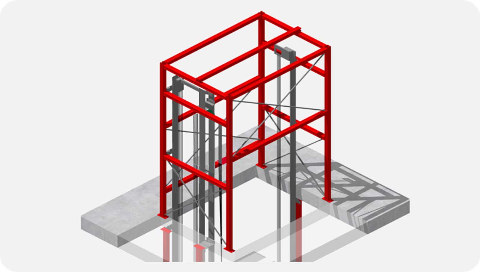
An additional, more complex application is given in modernization where modern traction elevators with machine-room-less (MRL) design shall replace old hydraulic machines. As the hydraulic design pushes the cabin up from the bottom often above the top landing floor, no load-bearing structure was needed in the building. Unfortunately, MRL elevators distribute the highest and most complex loadings to the building structure at and above the level of the top landing.
Modular support systems can be used to design and build a cage structure where the traction elevator machine and rails get assembled (Figure 11). The modular support structure takes up the forces from the elevator components and distributes them to the building via its anchoring at the top landing slab.
A standard modular design can be developed suitable for a specific traction elevator type of the manufacturer that supports simple, fast installation with much less noise and dust, as traditional construction activities involving concrete and steel members would cause to produce such a structure.
5. Conclusions
There are good reasons for omitting the design of an on-site partition wall in hoistways for group configurations. The quality of the fastening and installation of the guide rails is significant in regard to the elevator system’s safety and ride comfort. Supporting structures must be erected to fasten the guide rails between the elevator systems. Planning, design and installation of these supporting structures is generally given to a local subcontractor. This process represents a significant challenge for the central quality control process and carries considerable risks related to accidents, added cost and time delays in installation.
In many industries, modular systems have long been established for use in the design of supporting structures. Worldwide suppliers of these modular systems support global standards for modular-designed supporting structures in industry. The modular systems have been expanded in such a manner that they are suitable for use in the design of separation wall constructions for multiplex facilities in elevator installation (Figure 12).
The specification of standard solutions, based on this kind of modular system for divider beams used in certain system models, allows for central quality control and quality assurance relating to the construction of separation wall structures. The standardization of the solution is accompanied by a unification of the installation process, which is characterized by the handling of lightweight components that are assembled on-site without the need for separating or hot joining processes (such as welding etc.). This supports an entire range of advantages relating to avoiding the risk of accidents, as well as time and money savings, and the integration of the installation of the separation wall system into the elevator systems assembly process.
When the partition structure is specified in standards as an integral part of the elevator system model, the cost of providing it can be incorporated into the elevator manufacturers’ supply tools.
The great number of advantages posed by modular systems in creating separation wall structures will, in all likelihood, lead to these solutions becoming established worldwide in the future.
Acknowledgements
Thank you to Dr. Alexander Eberlein, team leader specials at Hilti’s Corporate Project Management Office, FL-Schaan in Liechtenstein for his support on the details on the FEM (finite element method) to support design calculation of elevator divider beams.
References
1. Merz, M. (2010). Practical Stress Behavior of Complete Rail Fastening System. Elevator Technology 18: Proceedings of ELEVCON 2010 (A. Lustig), Lucerne, p. 248-257. Elevator World, 2011, 59(6).
2. Merz, M. (2014). Modular Support Systems Replace Welded Support Structure. Elevator Technology 20: Proceedings of ELEVCON, 20 (A. Lustig), Paris, 214-226.
3. Merz, M. (2018). Added Value of Anchors following an Approval/ Assessment Standard. Elevator Technology 22: Proceedings of ELEVCON, 22 (A. Lustig), Berlin, 12-23.
Get more of Elevator World. Sign up for our free e-newsletter.
