Early Elevator Plants in New York City
Jan 1, 2013
A wealth of evidence concerning 19th century elevators survives. This evidence includes patents, line drawings, engravings and photographs of elevator machines and system components. However, very little that reveals how elevators were actually installed in buildings has survived. Although this topic was addressed in the section “From Cellar to Attic” in chapter seven of From the Ascending Room to the Express Elevator: A History of the Passenger Elevator in the 19th Century (2003, available at www.elevatorbooks.com), more work needs to be done. Your author’s recent research for new information concerning elevator installations yielded several plans of building mechanical floors and a few complete system drawings. This material constitutes a sufficient body of evidence to permit further investigation into this topic, and this month’s history article offers an examination of the elevator plants designed for three New York City skyscrapers completed in the late 1890s and early 1900s.
The first building examined was the 16-story Bowling Green Building (1895-1898), designed by William J. & George A. Audsley, which featured nine Otis hydraulic elevators. The building’s organization followed a normative arrangement for this period, utilizing a roughly “W”-shaped upper-floor plan, with the passenger elevators deployed in a continuous bank along an outer wall (Figure 1). The eight passenger elevators included two express elevators (rise: 260 ft.) and six general-use elevators (rise: 220 ft.). The ninth elevator operated in the building’s main stairwell and served as a combined freight/passenger elevator (rise: 235 ft.). The eight passenger elevators utilized Otis’ Standard Vertical Cylinder Engines (Figure 2). These elevators were powered by a “double power,” or “duplex,” system that could provide water at low (120 psi) or high (220 psi) pressure, depending on the load carried. Their operation was described by engineer Reginald Bolton as follows:
“In the Bowling Green Building, the duplex system of pressure has now been working successfully for four-and-a-half years. In that plant, a triple expansion engine pumps all the water required by the entire elevator service, but only to 120 [psi], sufficient for use with the average loads; a second compound engine then draws water from the first pressure drum at 120 [psi] and pumps to 210 [psi] in a second drum. The two supplies are piped over to the main valve, which is made with an extra lift, so that by pressing the lever in the car over to the last notch, water at the higher pressure can be taken into the cylinder. The cylinders are then reduced in size, and with the low-pressure water, are capable of carrying the car only with the average load at the proper speed. Instead of being 15-1/2-in. cylinders, they are only 12-1/2 in. in diameter. Under ordinary circumstances, that is, seven-ninths of the time, the operator carries his average load and gets his rate of speed by the use of the low-pressure water, but when he has an additional load, he puts his lever over to the farthest notch and takes in the high-pressure water.”
The mechanical diagram of the duplex system published by Otis engineer Thomas Brown in 1904 illustrated primary and secondary pumping engines, low- and high-pressure water reservoirs, a discharge tank and the vertical engine (Figure 3). This diagram was translated into reality in the Bowling Green Building. The machine-room plan shows the eight vertical cylinders in niches along the outer wall; the high- and low-pressure and surge tank arranged in a line adjacent to the cylinders, and three water (two compound and one triple) pumps near the tanks (Figures 4 and 5). Unfortunately, the plan does not depict the piping that connected the systems’ components. However, it does reveal that the combined freight/passenger elevator employed a horizontal hydraulic engine (likely an Otis High Pressure Engine) (Figure 6). While no explanation was provided for the shift in engine type, the drawing clearly reveals the impact this system had on machine-room space planning.
The 16-story Hudson Building (1896-1898), designed by Charles W. Clinton and William H. Russell, employed four Otis Standard Vertical Cylinder Engines with cars arranged in opposing banks in the center of the plan (Figure 7). The upper floor and machine-room plans both allocated the space necessary to add two additional cars, if needed. In this case, the machine-room plan depicted the pipes connecting the pressure and discharge tanks to the vertical cylinders. This plan, coupled with an elevation drawing of the machine room, permits a clear understanding of the character of this installation (Figure 8). A close examination of the plan and section also prompts questions regarding the nature of the elevator shaft and pit (Figure 9). The section depicts the shaft ending at a point even with the top of the basement floor, with the pit extending through the basement floor and ending approximately 12 ft. above the cellar floor. This pit design type was also depicted in Otis’ Standard Vertical Cylinder Engine engraving (Figure 10).
This aspect of the elevator installation prompts questions about pit construction, especially with regard to the question of what would happen if the safeties failed to the point that the car impacted the bottom of the shaft. However, given the consistent concern for safety expressed by Otis and other manufacturers, it may be safe to assume that this pit design simply reflected the mechanical and installation characteristics of this system type. This idea is supported by an examination of the machine room of the 15-story addition to the Mutual Life Building (1900-1904), which was also designed by Clinton and Russell. The plan of the machine room resembles that of the Hudson Building in its depiction of the complex system of piping, pressure and reservoir tanks, and elevator engines. This plant supported two banks of three elevators. The engines for the Cedar Street elevators (visible at the left side of the plan) were placed in a line at the end of the bank, while the engines for the Liberty Street elevators were spaced evenly across the bank (visible at the right side of the plan) (Figure 11). The fact that the Liberty Street elevators are indicated in the plan as dotted lines also reveals another factor occasionally encountered in planning these early installations – the Mutual Life Building had four below-grade levels: a sub-cellar (the lowest level), cellar, sub-basement and basement. The Cedar and Liberty Street elevator plants were located on different levels.
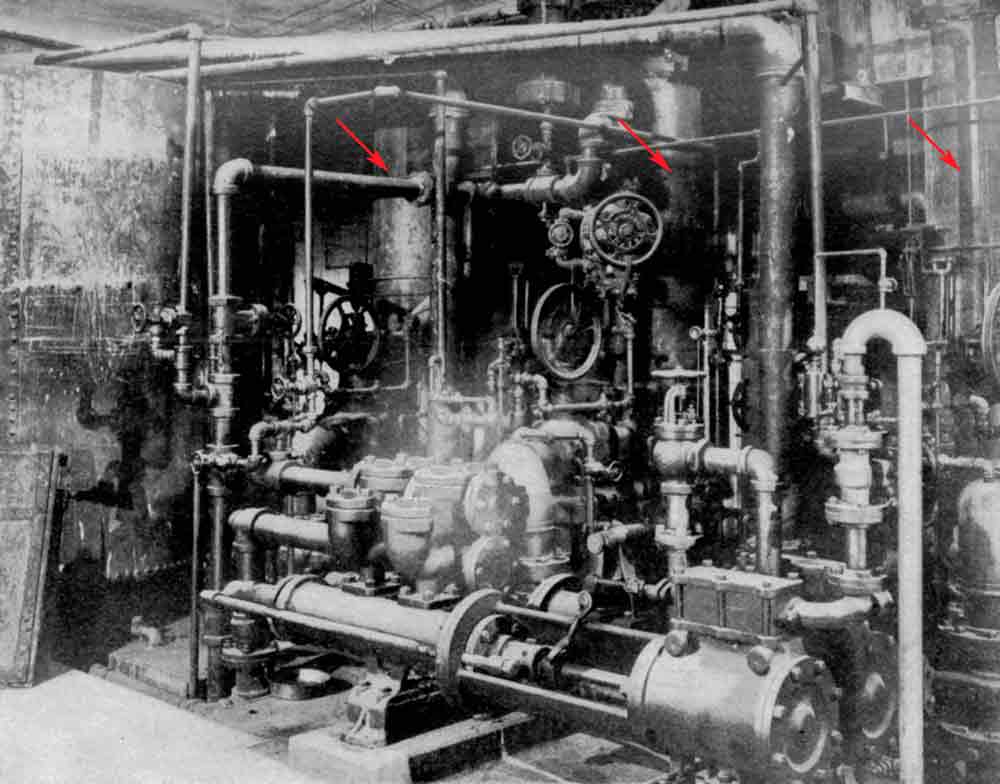
In addition to these drawings, a photograph of the Liberty Street elevator plant has also survived (Figure 12). The dense network of engines, tanks and pipes that effectively screen the vertical hydraulic cylinders seen in the background (indicated by red arrows) clearly precludes the presence of elevator pits at this level. Thus, this image helps explain the pit design noted above. It also serves as reminder that this aspect of elevator technology – plant installations – provides us with a very different view of elevator history. This alternative viewpoint is directly linked to the world of maintenance (Imagine working on these engines!) and realities of incorporating complex technologies into buildings. In the late 19th century, tall buildings were increasingly required to incorporate additional new and/or improved systems that dramatically increased the design challenges faced by architects and engineers. This has almost always been an aspect of elevator-plant design and installation, and, while today’s technology is radically different, the design challenge of integrating elevator systems into rapidly changing technological environments remains the same.

Figure 1: Typical upper-floor plan, Bowling Green Building 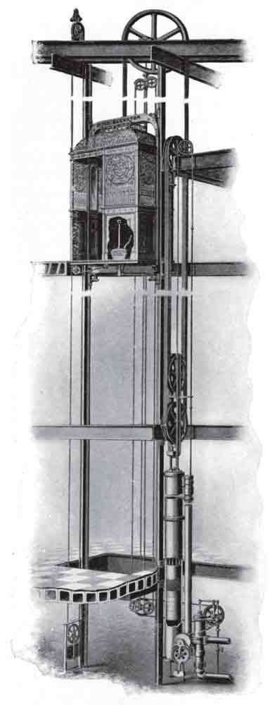
Figure 2: Otis’ Standard Vertical Cylinder Engine 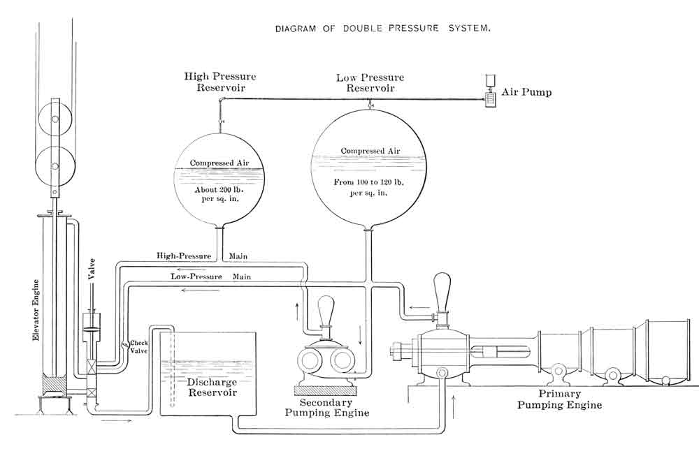
Figure 3: Double Power System diagram, Thomas Brown, 1904 
Figure 4: Mechanical floor, Bowling Green Building 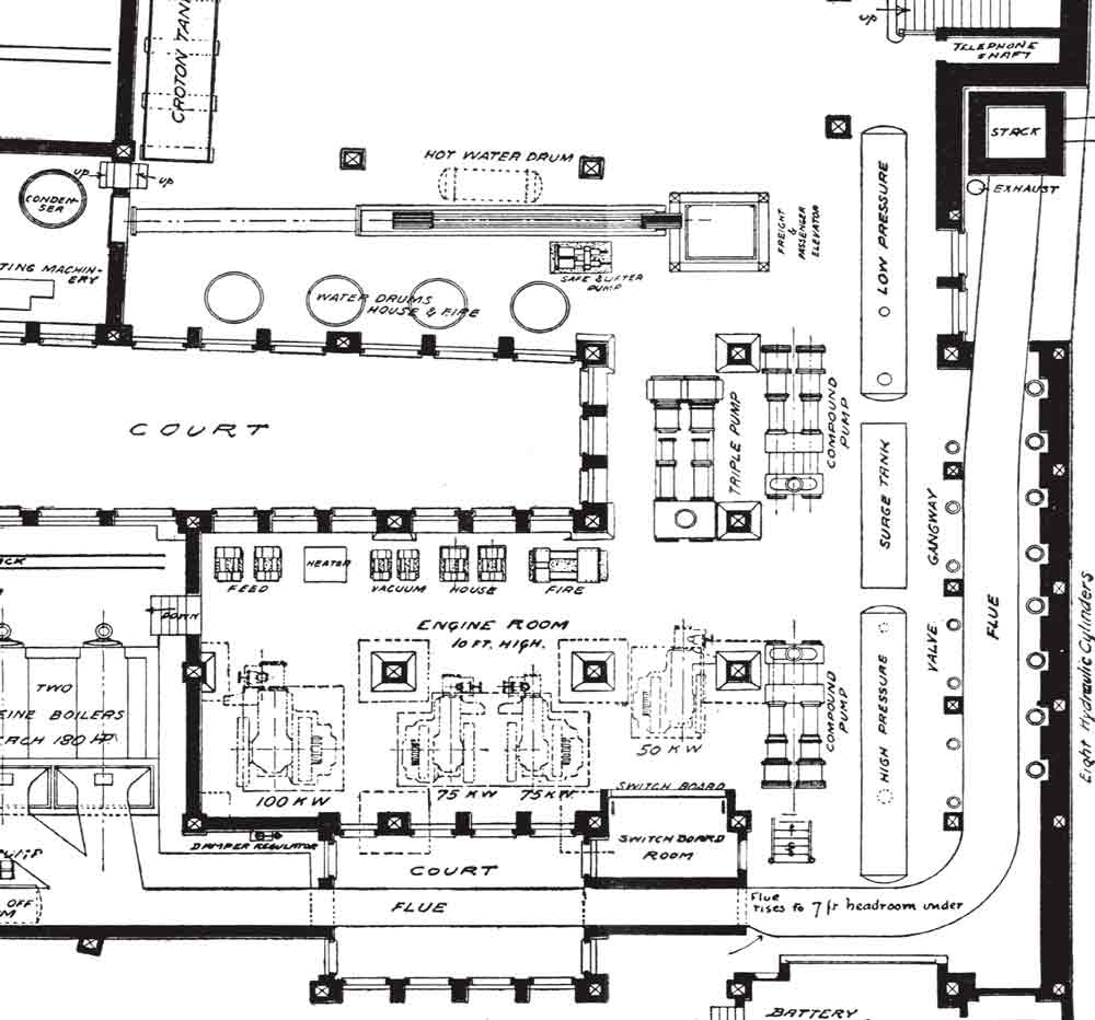
Figure 5: Detail of mechanical-floor plan, Bowling Green Building 
Figure 6: Otis Horizontal High Pressure Engine 
Figure 7: Typical upper-floor plan, Hudson Building 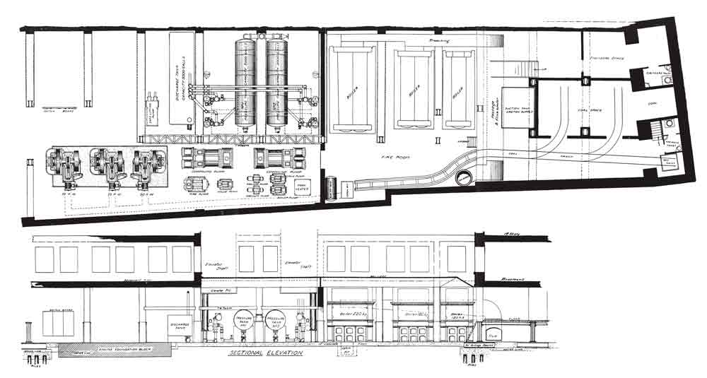
Figure 8: Mechanical-floor plan and section, Hudson Building 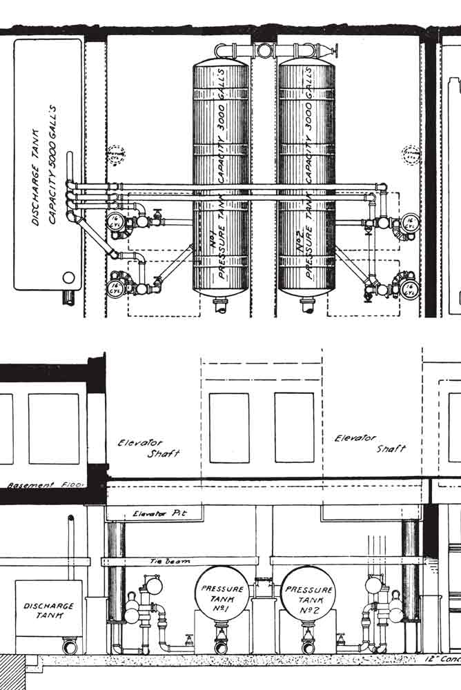
Figure 9: Detail of mechanical-floor plan and section, Hudson Building 
Figure 10: Detail of pit design with Otis’ Standard Vertical Cylinder Engine 
Figure 11: Detail of mechanical-floor plan, Mutual Life Building addition
Get more of Elevator World. Sign up for our free e-newsletter.

