This Product Spotlight details the development of and perceived need for Otis’ replacement of the centrifugal overspeed-governor subsystem and safety actuation module.
This article was first presented at the 2018 International Elevator & Escalator Symposium in Istanbul. For more information on November 2019’s event in Las Vegas and to participate,visit www.elevatorsymposium.org.
By Randy Dube, Peter Herkel, Dr. Pascal Rebillard and Rubén Sánchez Muñoz
Since the advent of machine-room-less (MRL) elevator systems, the elevator industry has observed some growing market trends that challenged engineering teams for years: hoistway size optimization, increased safety and installation-time reduction. One of the Otis innovations to address key customer requirements supporting these trends is the Electronic Safety Actuator (ESA) replacing the current centrifugal overspeed-governor subsystem and safety actuation module (i.e., safety linkages and lift rods) with a pair of independent electromechanical safety actuators — one on each side of the car — and an electronic Safety Actuation Board (SAB), which includes the dedicated circuits for the safety actuators, interface to a distributed safety control system and power supplies.
However, a pure replacement of the overspeed governor by an electronic one doesn’t answer all the safety requirements. Following a systems-design approach, the ESA is integrated into a distributed system of safety electronics extending the pure overspeed function into a set of interlocking functions. This distributed safety system is communicating over a serial bus to transmit both safety- and non-safety-related messages across the elevator control system.
The distributed safety control system collects discrete safety-related signals to assess overall safety status of the elevator system. The SAB receives car velocity data from an independent speed sensor and manages overspeed decisions. These decisions communicate overspeed status to the distributed safety system to signal the elevator control system to command the motor drive to remove torque to the elevator machine and engage the machine brake or activate the electromechanical safety actuators to control activation of the safety gear.
A model-based design approach is applied to ensure high reliability for the complex interlocking between the safety evaluation of the elevator through communication with the elevator control system and SAB on the car.
Introduction
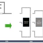
Since the aforementioned advent of MRL elevator systems in the 1990s, which was made possible thanks to the European Lift Directive, the elevator industry has observed some growing market demands to increase hoistway optimization, resulting in the emergence of systems providing low overhead or low pit.
Obviously, this has been and remains a technical challenge, because, in addition to the development of smaller and smarter components and subsystems able to fit in a reduced space, engineering teams must also take into consideration the following major requirements:
- To increase safety for both our mechanics and passengers without causing entrapments
- To decrease the installation time and make maintenance operations more efficient
The replacement of the conventionalgovernor subsystem with the ESA provides a number of benefits that enable meeting these requirements and, consequently, lead to a win/ win solution for our customers and passengers:
- Increased hoistway efficiency: More space because the governor, governor rope and governor-rope tension device are eliminated, while the safety linkages are significantly reduced.
- Decreased installation time: The ESA and safety can be assembled on the car-frame uprights in the factory, eliminating the need for field installation and adjustments.
- System health monitoring: The ESA will monitor the health of its subcomponents.
- Improved response time: Integration of an intelligent control unit allows for control algorithms. The response to freefall from contract speed could occur prior to reaching the code-defined maximum trip speed.
- No false actuation: Centrifugal mechanism-based governors may provide a false response to the elevator safety logic that will initiate stopping of the lift machine when not required, leading to passenger entrapment. The false actuation is caused by the mechanism being reactive to emergency stops, passengers intentionally bouncing the car, etc. when no overspeed conditions exist. An intelligent control unit using algorithms processing both velocity and acceleration can eliminate this problem.
The ESA is a new Otis design that combines overspeed
governor and Safety Actuation Module (SAM) functionality into a single interactive component. It is designed to perform the following primary functions:
- Determine if an elevator car is overspeeding beyond a certain threshold and alert the elevator system safety logic (PES- System) when this occurs
- Energize an electromagnetic actuator within each of a pair of SAMs mounted on the car-frame uprights to initiate engagement of a pair of adjacent mounted progressive safeties if the trip speed threshold is reached by the car or the car is accelerating at an undesirable magnitude (including a freefall condition)
- Discriminate abnormal passenger behavior and emergency stops from overspeeding conditions to prevent undesirable system reactions and passenger entrapments
- Facilitate system turnover, periodic testing and inspections required by authorities, and ensure safe working conditions are possible during service
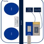
The ESA SAB uses electronic circuitry to process a velocity signal provided by an absolute position reference system via an industry-standard controller-area-network (CAN) bus interface. The ESA SAB communicates with the elevator’s PES-System through the elevator system car CAN bus. The ESA SAMs containing the electromagnetic actuators with magnetically coupled permanent magnets (PMs), connection to the safety gear and lever switches are integral to the ESA. Electrical wiring (e.g., cables) interconnects parts of the ESA and the ESA to the elevator system. Additional functionality enables self-diagnostics and communicating responses of fault conditions to the PES-System that indicate loss of integrity of its interfaces and overall readiness to execute its primary functions.
Current Overspeed Detection and Safety Gear Actuation Systems
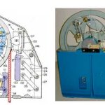
The traditional and dominant means of elevator overspeed detection today is with calibrated centrifugal mechanisms as part of “roped” governor subsystems. Centrifugal mechanisms take many forms, but all rely on established principles of rotational dynamics. The major advantage of these mechanisms is they require no power to function and rely solely on gravity and a means to rotate them. Consider the examples in Figure 2.
The elevator car’s vertical motion provides a correlated rotation of the mechanism; therefore, the fundamental elements are combined to create a valid elevator speed detection device. Normally, a tensioned governor rope wraps sheaves in a preferred configuration in which one sheave is connected to the mechanism (i.e., “the governor sheave”) and used to direct the speed correlation. This overspeed detection device is low cost, robust and a scalable implementation applicable to all elevator rises and speeds.
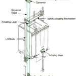
In addition to overspeed detection, another significant value of these “roped” governor subsystems is an ability to direct force to a car-mounted safety-actuating mechanism by decelerating the tensioned rope in various ways by creating a tension imbalance in different sections of the rope. This mechanism is normally located above or below the car and is traditionally formed of connected mechanical elements designed to engage the safety gear in a synchronized way. The dominant roping configuration used today is a simple loop with the ends of the governor rope connected to an actuating lever that is part of the safety actuating mechanism. The sheave connected to the centrifugal mechanism, or the governor sheave, is at one end of the loop fixed in a machine room or at the inside top of the hoistway and at the other end of the loop in the pit is a weighted idler sheave ensuring tension in the loop. Consider the illustration in Figure 3.
Sheave rope groove geometry combined with the rope tension avoids rope slip which would compromise speed correlation with car motion as described earlier. Alternate configurations combine the governor sheave in a weighted assembly in the pit for providing the rope tension and use only an idler sheave at the top of the hoistway. In these configurations, the governor rope is rotating as the car moves.
There are also fixed rope governor subsystems where the governor sheave and an idler sheave are contained within an assembly mounted on the car with the rope fixed at the top of the hoistway and tensioned by a hanging mass or spring in the pit. A mechanical element in the car-mounted assembly connects to the safety directly or the actuating lever part of the safety-actuation mechanism on the elevator car. Faster response and less rope and materials are some benefits of this configuration. An example is shown in Figure 4.
In all described configurations, one of three techniques is used to create a net “lifting” force to the actuating lever and subsequent motion of the car-mounted mechanism that leads to movement of the wedges or rollers of the safety gears and engagement with the guide rails, decelerating the car. The most popular technique uses a parallel jaw arrangement. At the required speed (i.e., trip speed), a moving jaw is positioned opposed to the spring-tensioned fixed jaw, applying a clamping force to the moving governor-rope portion above the actuating lever connection. Consider the example below.
Another relies on a high-friction rope groove geometry in the governor sheave (e.g., V-groove). When the sheave is abruptly stopped at the trip speed, it generates higher tension in the rope above the actuating lever connection than below it. Yet another combines a reduced contribution from the method of the previous approach using a round governor-sheave rope groove instead of a V-groove. In this design, most rope tension imbalance derives from forcing a single concave radiused spring-loaded cam or jaw against the rope wrapped around the governor sheave as shown in Figure 6.
Alternative overspeed detection (often named “ropeless”) and safety-gear actuation system designs have emerged in the last 10-15 years with intellectual-property publication increasing, but market penetration led by component supplier offerings has been limited. Elevator system OEMs have not transitioned appreciably to new systems with urgency. Some designs for overspeed detection have used elements rolling on one of the car guide rails to rotate forms of encoders, hoistway hung metal tapes (with or without proprietary printed patterns) read by car-mounted sensors and accelerometer-based systems. However, challenges with cost comparisons to existing systems, performance, complexity, increased failure modes, scalability, the need for software and power management, etc., must be overcome.
Barriers to new ideas are means to generate the forces to engage safety gears of various sizes in a synchronized way within desired times, compared with the traditional “roped” systems. All combined, cost effectiveness proves an enduring challenge, but rapidly declining cost curves of applicable building-block components such as accelerometers, noncontact sensors, PMs, etc., and an increasing Internet of Things-centric approach and acceptance of electronic/software-controlled safety functions have initiated a resurgence in new ideas.
System Integration Issues With Current Overspeed Detection and Actuation System
Overall, the dominance of the traditional solutions described is attributable to acceptable performance satisfying the needed functionality demanded by codes, proven reliability, limited and well-understood failure modes, low cost and wide commercial availability of the constituent components. However, from a system-integration standpoint, the use of traditional means of elevator overspeed detection using centrifugal mechanisms is a penalty for the following aspects:
- Hoistway efficiency: The overspeed governor must be installed either in the hoistway or on the car for MRL systems, or in the machine room. In all cases, a steel rope is needed for routing through the governor. The rope connected (typically to the cab) via a safety linkage actuating lever, and a governor-rope tensioning means is required. Last, the safety gears installed on both sides of the vehicle must be linked with a synchronization linkage that obliges location of the safety gear above the car roof level or below the car platform level, jeopardizing the opportunity to achieve low-overhead or low-pit systems, respectively.
- Car-frame design flexibility: The need for a safety-actuating mechanism connected to the governor subsystem to synchronously engage one pair (left and right) of safety gears consumes space on the car and adds mass.
- Installation time: A major disadvantage to the above-mentioned traditional solutions is the governor rope length dependence with rise and installation burdens inherent with the use of governor ropes, sheaves and rope tension devices.
ESA Description
Mechanical
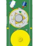
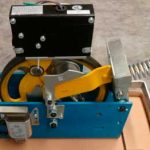
Mechanically, the ESA will integrate functions from the governor subsystem and safety actuation module. If car overspeed occurs, it is responsible for generating and transmitting sufficient force to activate the safety gear. To achieve this goal, we developed an electromagnetic actuator (Figure 7) that generates the force required from friction with the guide rail generated by an assembly formed of a PM and steel pieces.
The PM assembly is attracted and coupled to the steel-core coil, so the car can be moved without actuation of the safety gear, during normal operation. This attraction is produced without power by the field created in the PM assembly interacting with the steel core of the coil; this results in no energy consumption during most of the ESA’s life.
When necessary to engage the safety gear, the SAB energizes the coil to produce, within milliseconds, an electromagnetic field with the same polarity as the PM assembly, creating a repulsion force between both and deploying the PM assembly against the rail, due to the normal force created by the magnetic attraction of the PM assembly to the guide rail. When the car is moving, a friction force is generated, braking the PM assembly and transmitting a force through the link up to the safety gear’s wedge/ rollers upward relative to the descending elevator car to result in its engagement (Figure 8).
Pursuing EN 81-20, 5.6.2.2.1.1 d), this force generated will be at least twice the required force to engage the safety gear. As soon as the PM assembly is deployed against the rail, a lever switch will initiate a signal to the elevator safety logic, leading to the control system commanding the interruption of power to the lift machine, in compliance with EN 81-20, 5.6.2.1.5 and machine-brake activation. In case of accidental (undesired) single safety-gear engagement, this switch will detect it via initial motion of the PM assembly, followed by the SAB energizing both actuators, preventing the case of a single-side safety-gear actuation.
After safety-gear engagement, the elevator car must be raised until the PM assembly is coaxially realigned with the steel-core coil. After realignment, the SAB will energize the coil, creating a magnetic field with opposite polarity. This serves as an attractive force to couple the PM assembly to the steel-core coil, completing the actuator resetting.
All previous operations related to magnetic operations are affected by various magnetic airgaps. In order to keep these airgaps in an operational range, the complete safety actuation module can move horizontally relative to the elevator car frame upright and, thus, relative to the guide rail.
Electronic hardware and software
As mentioned in the previous sections, the ESA’s electronics perform the following three main functions:
- Detection of excessive speed in the car moving upward (EN 81-20:2014, 5.6.6)
- Detection of freefall and excessive speed in the car moving downward (EN 81-20:2014, 5.6.2.2.1)
- Pre-triggered stopping system for reduced clearance in the pit (EN 81-21:2018, 5.7.2.3)
The European lift standard describes the implementation of mechanical means; we have used an implementation in electronics. However, the rules for the design of electronics for safety-related applications defined in the European lift standard, i.e., EN 81- 20:2014, 5.11.2.6 referring to the tables in EN 81-50:2014, 5.16, are no longer considered state of the art. Thus, the IEC 61508 standard was selected. It provides guidance for the implementation of electronics in safety-related applications and guidance for the process to be followed when such safety electronics are designed, verified and validated.
As the lift standard asks for a mechanical solution, the Safety Integrity Level (SIL) of the functions are not defined, nor mentioned in Annex A of EN 81-20 and EN 81-21, respectively. The first step was to determine the required SIL by performing a risk analysis and achieving confirmation from a Notified Body. The next step was to identify use cases for operation of the ESA when the lift is used by customers and a service person, respectively, and during erection and commissioning of the lift.
The result of the analysis is a complete set of high-level requirements for the ESA in relation to the whole lift system. Using methods defined in systems engineering, the functional allocation for the SAB is defined, and the interface to the actuator, the other safety system and the lift control and car speed sensor system are defined.
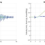
The benefit of the system engineering approach is it enables the ESA to deal with abnormal passenger behavior. By combining the acceleration and velocity of the car movement from jumping and PM assembly deploying Actuator resetting rhythmic bouncing of a person can be detected and differentiated from the other causes of car shaking (e.g., emergency stopping).
Model-Based-Design (MBD) Approach
A framework for analyzing and exploring the operation of the actuator was developed to assess critical parameter performance of the safety gear actuation. A simulation framework was used to explore the different hardware architectures and identify the appropriate software algorithm to perform the governor function in the required reaction time with the defined actuator hardware. A second framework for designing the software functions was set up to improve the software design process and improve the quality of the software. This framework is commonly named MBD.
Two models are derived from the requirements written in natural language: one with the focus on functional behavior — a functional model, and the other with the focus on implementation — a design model. First, both models are analyzed, executed and tested separately to check the design correctness. Here, an automated test-case generation supports the design-verification task, and aspects of coverage analysis are considered. In a second step, both models are executed with the same test vectors, and the execution result of both models are checked for consistency. In a third step, the test cases generated from the functional model are executed on the design model, and the test cases generated from the design model are executed on the functional model to validate the design. This last step is repeated using the executable code generated from the design model to verify and validate the generated software code. Additional tests are performed on the generated software code to cover the full aspects on testing of safety-related applications as indicated in the standard for safety electronics and other state-of-the-art literature.
Technical Challenges
Besides the business-value deliverables and cost targets inherent with any product development, the need to overcome several technical challenges shaped the resulting design. Broadly, these challenges can be grouped into three categories: system integration, performance and testing. Additionally, project structure played a role in the execution of the design.
System Integration
Mechanical
System integration included basic overall physical size, mounting structure and the requirement to design a compact arrangement of the needed components that would interface to the car frame (each side) and operate with the specified safety gear. The type of safety gear operated by the ESA is not 100% “symmetric”; therefore, some lateral car movement requires accommodation and the need for some guidance of the actuator housing with respect to the guide rail. The challenge here was to control the amount of guidance without creating unacceptable acoustic noise, while providing for a long wear life for any parts in contact with the rail. Rollers using a biasing PM to ensure guide- rail contact were chosen to accomplish this, creating some overall housing physical-size penalty. Synchronization of the left/right actuators, electrically and mechanically, was also analyzed from a DFMEA perspective to avoid safety-gear application potentially distorting the car frame.
Electronics and Software
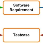
The most significant challenge faced during the design was traceability between a requirement; its implementation in software; and, finally, the verification test. The challenge was intensified using different tools for the three domain elements.
The issue was solved by selecting a set of tools interfacing to an application lifecycle management tool, supporting traceability of requirements at the system level to requirements at the hardware and software level. This provided a trace to the implemented software code and provides independent links to the test cases if they were automatically generated by the MDB tool or generated manually, and, finally, provides a trace to the test result.
Performance
Magnetics and electromagnetics design are key to the operation of the ESA. A challenge was balancing the interdependency of the passive PM and active electromagnetic circuit designs required to ensure rapid magnet deployment, adequate force to move the safety-gear wedges and an ability to remove the PM assembly from the rail to recouple it to the steel-core coil with high reliability.
Commercial magnetics design software was employed, along with circuit analysis optimization and empirical testing, to converge on the final design. Demonstrating SIL 2 and 3 reliability (based on function) drove considerable design iterations and enabled the team to learn from failures and improve the design.
Testing
Conventional test infrastructure (i.e., freefall hoistways, elevator systems and environmental chambers) are not adequate to test the ESA design at the detailed levels necessary to understand the performance of the magnetic elements and their driving circuits, and software of the ESA. Consequently, supplemental test rigs and fixtures were developed, and test procedures to focus on those attributes most critical to ensuring desired performance and reliability were refined over time. The combination of new and traditional test infrastructure enabled the necessary experimentation and refinement to achieve the targets.
The ESA project transitioned from an advanced technology- development phase for ideation, concept feasibility and risk assessment into a product-development project over several years. An international development team comprising less-experienced and more-senior engineers/technicians/managers located in four countries (Germany, Spain, France, and the U.S.) challenged overall organization and demanded strong cooperation to work effectively. Otis embraces this decentralized global structure for most of its development projects, but this project’s departure from the traditional method of safety-gear engagement enhanced the need to draw on the collective contributions from all.
- Figure 1
- Figure 2
- Figure 3
- Figure 4
- Figure 5
- Figure 6
- Figure 7
- Figure 8
- Figure 9
- Figure 10
- Figure 11
- Figure 12
Get more of Elevator World. Sign up for our free e-newsletter.

