Elevator Emergency Operations
Nov 1, 2014

Recommended safety features and how to make an elevator fully compliant with the codes in effect are discussed.
Passenger elevators play the most important role in vertical transportation within most buildings. The design and operational features of an elevator require thorough review for predicting the emergency conditions a passenger could face while traveling in an elevator and suitable methods to manage such emergency conditions. Various emergency operational features have been developed over the years to keep the passenger fully informed and assured of complete safety, and to rescue entrapped passengers. These features have been developed through user experience, and the development of elevator safety codes, international building codes and life safety codes.
This article discusses various emergency operational features recommended on modern elevators. It aims to apprise architects, engineers and owners of the importance of incorporating and procuring a fully compliant elevator and ensuring the safety of elevator users.
Essential Services in Emergency Conditions
Any emergency condition would require the continued availability of a safe environment and effective communication means until the condition is resolved. For entrapped passengers, the provision of sufficient lighting, ventilation and communication means are very essential.
Emergency Power Supply
Depending on its occupancy type, a building could be provided with various types of low-voltage power-supply systems, such as “normal,” “essential” or “emergency (life safety)” power. In normal power, virtually all building services are connected to the city power supply. In the case of a citywide power failure, the systems that must function to retain the normal operation of the building should be provided with essential power, which is usually supplied by the generator. In emergency conditions (such as fire, earthquake and other evacuation scenarios), systems that must remain operational to carry out rescue operations are provided with emergency power, which is supplied from the generator but with multiple redundancy to protect the power-supply branch.
Only a few preselected elevators (often, one from each group) are classified as essential systems, while firefighters’ and evacuation elevators must be pre-identified and provided with emergency power to successfully manage emergency scenarios. Centralized monitoring systems, communication systems, air-conditioning, pressurization, ventilation and lighting systems related to firefighters’ and evacuation elevators must also be connected to an emergency power supply so essential status information, control features and communication features will be available even in emergency conditions.
In-Car Lighting
Emergency lighting must be adequate for passengers to identify the car-operating panel and the intercom/alarm buttons. Emergency lighting is usually supported by a rechargeable battery. However, battery-level/charging-status monitoring is not often employed. In ideal cases, a battery-level warning indication/beep should be provided, and the starting of the traction machine must be prevented in case the battery charge level is lower than the minimum required.
The same concept is adopted by a few manufacturers in the “brake release mechanism” of machine-room-less elevators. The mechanism is supported by a battery bank, and the battery charge level is monitored. Further elevator operation is prevented by the safety circuit in case the battery charge level falls below the minimum recommended. Alternatively, an “emergency light test” button could be provided in the control cabinet. This button enables quick verification of the proper functioning of an emergency light. It disconnects main car lighting and connects emergency lighting at the press of a button.
Modern elevator car decorations employ innovative car lighting. Architects prefer to have emergency lighting as part of main car lighting (instead of a separate emergency light bulb). The interior decoration takes priority, and, in the process, the factory-supplied emergency lighting is modified locally by installers using nonstandard components and circuitry. Reliability of such local solutions is questionable, and errors are not identified until a real breakdown happens.
In-Car Features for the Disabled
While under emergency lighting, improved visibility and communication features are required for trapped passengers with disabilities. Complying to accessibility standards will help in meeting the requirements of the disabled. For example, push buttons with Braille and other tactile markings will help the visually challenged to identify the intercom/alarm buttons. A button with a response beep will assure the user of registering a call. Similarly, providing an induction-loop system will help deliver emergency messages to users with hearing difficulties. “Call-in-progress” and “speak now” indicators help the disabled effectively communicate with the external rescue service.
Alarm button and microphone/speaker locations are critical. These must match the requirements of users in wheelchairs, in order to have a clear conversation.
In-Car Ventilation
Car fans typically do not work when an elevator is in a power-failure condition. This may make some trapped passengers have difficulty breathing. Natural ventilation slots are provided at the top and bottom levels of an elevator car to aid in air circulation. However, such ventilation slots are often blocked when elevator cars are covered with decoration panels. This could make air circulation impossible. Care should be taken not to block such ventilation slots on the elevator car shell.
In-Car Communication Systems
Reliable communication systems are essential to raise an alarm, identify the location of an emergency and communicate emergency requirements clearly to an external rescue service. Intercom systems with battery-power backup must be provided with relevant audio/visual indicators to communicate the requirements clearly. On large projects with many elevators, each elevator car must be labeled clearly to correctly guide the emergency-service provider.
A centralized emergency command center should be provided on large projects. All the elevator cars must be positively linked to the command center, and proper audio/visual alarm signals must be provided. Labeling each elevator is mandatory in order to identify an incoming call. Such centralized intercom systems are sometimes part of an elevator supervisory panel (watch board), which functions with a single-phase power supply point. Such systems must be pre-identified and connected to the emergency (life safety) power-supply circuit.
While decorating the elevator cars, care should be taken not to block the escape hatch, but to have an easily operable hatch on the suspended ceiling, too.
In-car visual communication screens/indicators can also be employed to display emergency messages. If this is the case, it is especially important the messages are in local languages. Including an induction-loop system will help the hearing impaired to converse clearly with the external rescue service.
Where a dedicated, 24/7 emergency management center is managed by the elevator manufacturer at the project’s location, an auto dialer should be installed to dial preprogrammed external service-station numbers. Auto dialers should be self monitoring to ensure proper operation at all times.
Passenger Entrapment and Rescue Operations
Even though modern elevator systems have become more reliable, passenger entrapment is one major emergency condition in which foolproof systems are necessary. Effective communication equipment is required to talk to the person(s) trapped inside the car, advise them of the rescue work in progress and instruct them during the rescue process.
When City Power Is Available
Passenger entrapment can occur in both conditions: with normal power available or during the failure of normal power. The former could be due to an equipment malfunction, a defective safety circuit, etc. Elevator machines are generally provided with a “hand winding wheel/arm” for manual rescue. Hand winding shall be employed on smaller elevators with gear reduction systems. However, on large elevators, without gear reduction, the effort to turn and control the hand wheel is quite high, making it necessary to use electrical emergency operation means, located within the machine room.
Usually, a “hand winding wheel/arm” is removable. The wheel/arm is located within the machine rooms, and it is installed on the machine only when required. Here, an electric safety device must be provided to disconnect elevator power during installation of the wheel/arm on the machine.
During City Power Failure
When city power fails, elevators are immediately stopped using the motor brakes, and the passengers are (at least initially) trapped inside the car. Many modern elevator systems employ “automatic rescue devices,” which supply battery power to open the brake and move the car to the closest landing.
The battery charge level of the automatic rescue device should be monitored to ensure proper operation when needed. In case the battery charge level is below the minimum recommended, further elevator operation should be prevented by the electrical design. To verify the capacity of the automatic rescue device, it is recommended to move large-capacity elevator cars on battery power over long distances. Particularly in express elevator shafts, emergency-rescue openings are provided every 11 m, but their occurrence sometimes exceeds this distance. In such cases, the battery bank of the automatic rescue device should be sufficient to move the cars across these distances.
Some elevator installations utilize “essential power” supplied from the generator to carry out automatic rescue. On large projects with many elevators, it is not possible to accommodate all the elevators within the generator power supply. Due to generator capacity limitations, it is usual that only a few elevators, at maximum, in any given building are designed to run under generator power. However, as opposed to “automatic rescue devices,” automatic generator power-transfer operation is employed to temporarily provide generator power to every elevator for rescue purposes. This is done in a pre-determined sequence, one elevator after the other.
While automatic generator power-transfer operation may work with smaller elevator groups, it will cause considerable concern with larger elevator groups. For example, consider a large, eight-elevator group. If the generator power is to be transferred to eight elevators one after the other, the passengers trapped in the eighth elevator would have to wait for an extended time and will go through more trauma than the passengers trapped in the first elevator. Such operations and the time taken for rescue should be reviewed in detail. Accordingly, automatic rescue devices must be employed as the first choice.
Entrapment Due to Unmovable Car
When the elevator car overspeed safety gear has been activated, the car becomes jammed on the guide rails, and it is no longer movable. Similarly, the drive sheave could become jammed due to a mechanical failure, after which the car is not movable. Under the circumstances, external rescue is carried out through the emergency escape hatch on the car roof. Even though the EN 81-1 code does not clearly state that an escape hatch is mandatory on passenger elevators, the possibility for a car to become stuck between two landings is possible, making an escape hatch necessary. Without an escape hatch, the elevator shell would have to be forcibly breached to gain access to the trapped passengers. EN 81-1 recommends a minimum size of 500 X 350 mm.
It is, however, mandatory to provide an escape hatch if the elevator has been designated as a firefighters’ elevator. The required hatch is larger in size (500 X 700 mm) unless the car’s capacity does not exceed 630 kg, in which case a smaller 400- X 500-mm hatch is allowed.
It is preferable for manufacturers to supply a standard landing door with a proven door-locking mechanism, rather than fabricating a custom-designed access door and its door safety lock.
Even if an escape hatch is provided by the elevator manufacturer, the interior decoration of the car and the suspended ceiling may permanently obstruct the hatch, rendering it unusable. While decorating the elevator cars, care should be taken not to block the escape hatch, but to have an easily operable hatch on the suspended ceiling, too.
For express elevators with nonstop zones, emergency doors must be provided every 11 m. Such openings should be properly interlocked with the elevator safety circuit to prevent elevator operation in case an emergency-access door is opened. Ideally, these specifications are the same for elevator landing doors. It is preferable for manufacturers to supply a standard landing door with a proven door-locking mechanism, rather than fabricating a custom-designed access door and its door safety lock.
Alternatively, car-to-car rescue can be employed, provided there is an adjacent car available within a maximum horizontal distance of 750 mm. However, there is a possibility that there are separator (divider) beams between the two cars in rescue position. The rescuer and the person(s) being rescued may be required to cross/climb over the beams and rails in the way. This is a risky condition and must be handled appropriately by the rescue team.
Firefighters’ Emergency Operation
As a standard of the Firefighters’ Emergency Operation procedure, all the elevators are provided with Phase 1 recall (i.e., to recall all the elevators to the main exit floor) in the case of smoke-detector activation from the elevator lobby, hoistway and machine room. The elevators are then parked at the exit floor to prevent further usage by the public. On each building project, designated firefighters’ elevators (Phase 2) are identified and connected to protected emergency power-supply systems and central-monitoring systems at the fire command center. It must be noted here that the life safety code NFPA 101 requires that all new elevators be provided with firefighters’ emergency operation (Phase 2) requirements.
Firefighters’ elevators are then utilized by the emergency personnel in Firefighters’ Operation Phase 2. Firefighters’ elevators should be connected to protected emergency power-supply systems and central monitoring systems at the fire command center. The NFPA 5000 Building Construction and Safety Code requires that all high-rise buildings have a fire command center wherein the essential status of elevators is monitored, along with the Phase 1 recall switches and emergency power-transfer operation switches.
Firefighters’ elevators should be well protected against water to keep them in working condition for an extended period during a firefighting operation. Water discharged through firefighting hoses and sprinkler systems could enter the firefighters’ elevator’s shaft through the landing-door openings. It is recommended to raise the door thresholds with a slope and introduce large floor drains to remove the excess water.
For the firefighters’ elevators, it is recommended to waterproof (IPX3 protection at a minimum) electrical components within a 1-m distance from landing doors. All pit electrical equipment within 1 m of the pit floor should be provided with IP67 protection. Suitable water-level sensors must be installed in the elevator pits to ensure the water level in the pit does not rise more than the level of a compressed buffer.
Emergency Power Transfer Operation
Due to limitations in generator power, only a preselected elevator(s) is provided with generator power. In such cases, the International Building Code requires this power be transferable to any other elevator(s) within the same group. This helps improve redundancy. In case the preselected elevator(s) is unable to run due to a malfunction, the available emergency power is transferred to another elevator(s) within the same group so the rescue/firefighting operation can still be carried out.
The design of low-voltage electrical distribution systems must accommodate the emergency power transfer operation and include such suitable electrical hardware as automatic transfer switches. The elevator controllers will also require identification signals to differentiate between normal and emergency power supply.
Earthquake/Seismic Emergency Operation
Buildings in seismically active regions must be provided with seismic detection systems and, if desired, primary (P-) wave detection systems. Seismic detection systems should be placed in the lowest position of the elevator shaft (i.e., the pit floor). These systems detect the ground acceleration (tremors) of an earthquake. The system interfaces with the elevator controllers. Upon activation beyond the preset trigger value, the elevator, if it is at a landing, is removed from service until the seismic activation is reset. If the elevator is in motion, its speed is stopped, and it is moved slowly to the nearest landing, avoiding moving toward the counterweight.
Seismic acceleration due to an earthquake can also disturb the main power supply. Elevators must be provided with automatic rescue devices to avoid passengers’ entrapment within the car.
Seismic detection systems should be provided with enough standby battery power supply for 24 hours of operation. The system should be self monitoring, and its interface with the elevator controller must be verified every 24 hours.
It is recommended to install displacement switches on counterweights. These are activated in case the counterweight is dislodged from its position between the guide rails. If an elevator moves when the counterweight has come out of the guide rails, it could come into contact with the car. A loose-hanging counterweight could also damage other shaft equipment, ropes and cables. When activated, the displacement switch prevents normal operation of the elevator.
P-Wave Sensor Operation
P-waves travel faster and are less destructive than secondary (S-) waves. P-waves are detected by the seismic sensors. S-waves travel slower but cause greater destruction. Detecting P-waves could aid in safely offloading elevator passengers and parking the elevators until the destructive secondary waves pass through the building’s location. Seismic sensors detect extremely small accelerations due to the P-waves. Both the seismic detection switches and the seismic sensors could be integrated with the elevator supervisory panel at the fire command center to provide relevant alarm.
High-rise towers more than 200 m and slender towers more than 150 m tall may require building-sway emergency operation.
Building-Sway Emergency Operation
High-rise towers more than 200 m and slender towers more than 150 m tall may require building-sway emergency operation. Depending on the location of the building, the built mass of the tower and the elasticity of the structure, a high-rise tower may move under high wind conditions. Long-lasting earthquakes can also cause such buildings to vibrate laterally, causing them to sway. Such movement sets the tower in oscillation on its own frequency. Elevator equipment on such towers (especially compensating ropes, governor ropes and main suspension ropes) face the risk of oscillating (excitation under resonance) with the building. When the frequency of the tower’s movement resonates with the frequency of the ropes and cables, the amplitude of the oscillation grows and could build to dangerous levels. High amplitude of oscillations could cause the rope and cables to slam against other shaft equipment and become entangled.
During the design stage, a building’s sway properties should be identified and simulated, along with the elevator equipment’s sway properties. Zones that cause resonance are to be identified and marked as risky. Ideal parking positions for the elevator (that do not cause resonance) are identified.
Structures that require building-sway emergency operation must be provided with appropriate sensors, such as those for wind speed and building sway to detect a tower’s movement beyond the preset threshold value. When a building-sway detector is triggered, depending on the severity, an elevator’s operational speed is reduced, and/or calls to risky zones are not accepted, and/or the elevator is moved to the safe zone and parked, out of service, until the building-sway trigger is cleared.
Elevators must be provided with many emergency-operation features to ensure the complete safety of passengers.
Conclusion
Elevators must be provided with many emergency-operation features to ensure the complete safety of passengers. They must also be provided with emergency features that reduce and/or prevent damage to the installation itself. Architects and engineers, with the help of a specialized elevator consultant, should carefully evaluate project requirements and identify the implications and consequences of deleting any emergency operation. Requirements must be clearly identified early in the planning stage, and negotiations must be made between the architects, engineers and project owners to include the maximum amount of safety and emergency operations to safeguard users and the elevator installation from the dangers that can be presented in emergency scenarios.
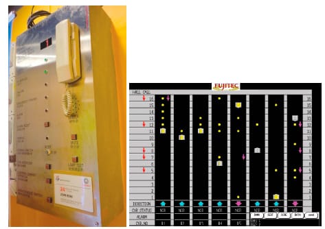
All centralized monitoring and communication systems require a protected power supply. These images show elevator supervisory systems that require an emergency power supply. 
Local modification to factory-supplied lighting is not recommended. 
(l-r) “Call-in-progress” and “Speak now” indicator illumination 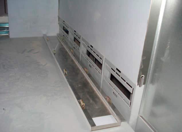
Ventilation slots at the bottom level of an elevator car 
Centralized intercoms must be labeled for clear identification of the calling elevator. 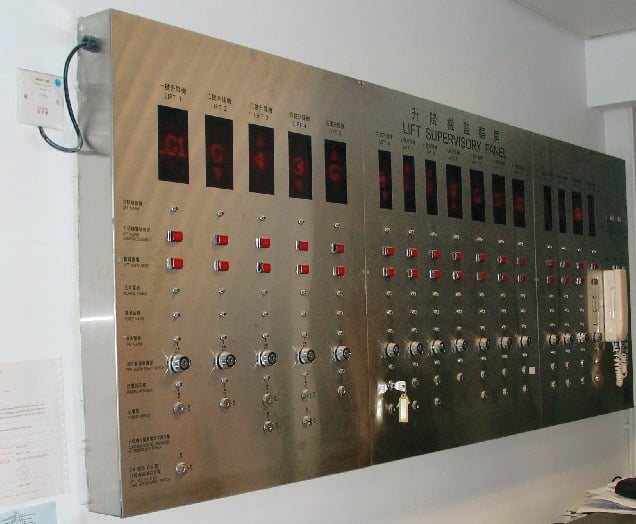
A large supervisory panel with a centralized intercom system 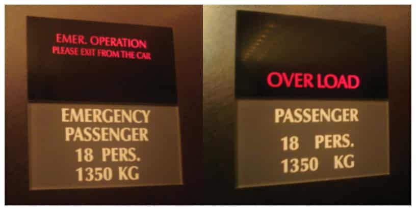
Visual indicators being used to display emergency messages. 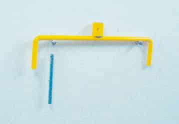
A removable hand-winding arm with brake release lever 
The emergency power-transfer operation switch on an elevator supervisory panel 
Escape hatch on an elevator car roof permanently blocked by the car’s suspended ceiling 
Typical arrangement of a Phase 2 Firefighters’ Emergency Operation unit 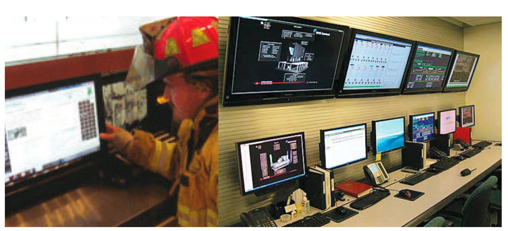
A typical fire command center 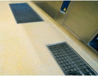
Floor drains in an elevator lobby 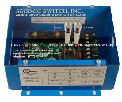
A Seismic Switch, Inc. ground motion detector 
A typical counterweight derailment switch 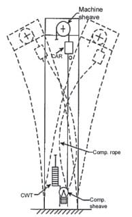
Illustration of building and rope sway 
A sample compensation rope motion graph (x-axis = lateral; y-axis = vertical)
Get more of Elevator World. Sign up for our free e-newsletter.