Elevator Hoistway Doors
Apr 1, 2015

Failures of door guiding means and door safety retainers on horizontally sliding doors can cause catastrophic injury to someone falling through a hoistway door into the hoistway when the elevator is not present. Knowledge of the significant elements of the design when performing elevator door installation and maintenance is critical for safety. This Continuing Education article will provide the information needed to ensure elevator personnel understand the designs used in the industry, the forces they are designed to resist and the importance of maintaining doors and related equipment.
Learning Objectives
After reading this article, you should have learned:
♦ Maintenance on door guiding means and retainers is required by code.
♦ The ASME A17.1/CSA B44 Safety Code for Elevators and Escalators has been updating the required strength of door panels since 1955.
♦ Door panels are designed with high strength to ensure human contact with the door panel does not expose a fall hazard into the hoistway.
♦ Components must only be replaced with the same brand of components, unless the listing agency approves the difference.
♦ Main landing hoistway doors need more frequent maintenance to ensure the components do not become so worn they cannot function as designed.
♦ The adjustment of up-thrusts (eccentrics) is critical to ensure door-panel retention.
♦ Labels are required to show certified testing was performed and was successful.
♦ The design and testing of hoistway doors are important to the safety of passengers.
A17.1/B44 Requirements
The ASME A17.1/CSA B44 Safety Code for Elevators and Escalators prescribes the design, testing and maintenance of door systems. The strength of door panels has changed from 1955 to 1990; the design requirements were 250 lbf (1,112 N) applied to the center of the hoistway door panel. In 1993, this was increased to 1,125 lbf (5,000 N). Then, in 1996, because of the addition of door retainers, door guiding means were reduced to their present-day value of 560 lbf (2,500 N).
Requirements for entrance fire testing also changed over the years. It was first required in 1955; therefore, doors older than this will likely not have a label, nor be required to have one. Those manufactured after this year are required to have a label.
Design Requirements
Design requirements call for door panels to be provided with door-guiding means typically consisting of door rollers and up-thrusts (eccentrics) at the top of the door panel and gibs on the bottom of door panels. Gibs are required to engage the sill groove a minimum of 6 mm (1/4 in.). Adjustment of eccentrics vary slightly from manufacturer to manufacturer; however, it is required that with center-opening doors, the door panels cannot open more than 20 mm (4/5 in.) when the panels just above the sill are pried apart. This is achieved only by setting the eccentrics 0.006–0.012 in. from the underside of the door track. This also ensures the rollers cannot be pushed off of the door track and dislodge the door panel.
In 1993, A17.1 required safety retainers on both the tops and bottoms of door panels, in addition to door guiding means, to ensure the door panels would be retained should the door guiding means fail (Figure 1). Retainers are required to engage to a depth specified by the entrance manufacturer.
Strength Testing
Strength testing of an entrance design is typically performed by the entrance manufacturer, generally tested in house, and signed off on by the design engineer, manufacturing engineer and management. When successfully strength tested, it is documented for code compliance, then sent for fire testing before production and sales.
There are two types of strength tests: a static load test and an impact test. They are equivalent in establishing the strength of the entrance and the door panels tested. The static load test consists of laying an assembled entrance on sawhorses with the lobby side of the door panels facing up, the gibs in a groove, and the adjusted door rollers and eccentrics on the door track. Weights are successively added until the gibs or door rollers and eccentrics fail, the panel bangs to the floor, and the weight is recorded. The same test is repeated with the safety retainers. The door rollers and eccentrics and gibs alone must retain 560 lb/ft. (2,500 N). The top and bottom safety retainers must retain 1,125 lbf (5,000 N). The impact test has the entrance upright and fixed in place, and a weighted bag is swung into the center of the panel applying a force. The higher the bag begins its swing, the higher the velocity at impact, and the higher the force. An example is shown in Figure 2. Either test result must demonstrate no appreciable permanent displacement or deformation of any parts of the entrance assembly resulting from the test up to the required rating.
Fire Testing
The code further requires entrance assemblies be fire tested to UL 10B, NFPA 252 or CAN4-S104 by the manufacturer to verify the design; then, labels are required to show certified testing was performed and was successful. A third-party testing laboratory must perform fire testing, and the results must be certified. There are multiple test standards, because Canada has its own standards, and some AHJs specify a particular standard. These are considered equivalent, though.
This test requires a complete sample entrance assembly be mounted on a large rolling platform, arranged as intended by the manufacturer to be installed in a building, at the testing facility. The entrance assembly forms one wall of a large oven, then is tightly connected and sealed so the entire lobby side of the entrance is exposed to the oven’s heating elements.
The oven heats the entrance assembly to over 1,800°F (982°C) for a time based on the fire rating desired. In the case of standard elevator entrance assemblies, 1.5 hr. is typical. At these temperatures, all plastic components will melt and burn away, leaving the door panels to be retained in the entrance assembly frame by only the remaining metal safety retainers designed to survive this temperature.
After the specified time at the temperature has expired, the oven is turned off. Then, the rolling wall is moved into position for a hose spray test. The lobby side of the hot entrance is sprayed with a 1-1/8 in. (29-mm) fire-hose nozzle from 20 ft. (6 m) away at 30 psi (207 kPa) for 20 min. delivering 58 lbf (258 N) onto each element of the enclosure assembly.[1] After water impact, this severely weakened entrance cannot present any openings greater than 2.88 in. (73 mm) to a wall and no more than 1.25 in. (32 mm) around a door panel. If the metal bends beyond the test limits, the entrance is rejected and must go back to the manufacturer for further design revisions, then a new entrance must be tested.
A successfully tested entrance assembly design is then “listed” with the testing laboratory to provide traceability to the testing conditions and assembly components used during the test. Then, the entrance is “labeled” as evidence of successful completion of the test. All listing and labeling requirements in the code have a similar process, just a different standard reference and test procedure.
Manufacturers of listed and labeled entrances are required to have quarterly inspections by the certification laboratory at the manufacturing facility in a process known as “follow-up service” or, as the code refers to it, “factory inspections.” Differences in the design discovered at the time of follow-up service inspections can cause manufacturers to stop production or, worse, have recalls of sold product. Manufacturers are very careful to maintain the design and send instructions to purchasers and installers to ensure construction and assembly in the field are done correctly as designed, tested and certified. The factory inspections end when the product is no longer in manufacture.
The labeled entrance assembly must be maintained throughout the lifecycle of the entrance in the field; if not, the entrance can be out of compliance with the certification requirements and the elevator code, because what is installed is not what was tested and certified. Modifications made by an installer or maintainer can affect the tested and certified strengths, so reference must always be made to the original instructions when making any change in the field. It is critical for the installer to keep the records and instructions to make repairs and replacements of components according to the manufacturer. A call to any manufacturer is the most prudent action by which to obtain the correct information.
Elevator personnel need a full understanding of the critical nature of component listing and labeling. Hoistway entrance listing specifies the hoistway door components used during testing. These components must not be from a different manufacturer without review by the listing agency and OEM. Maintenance personnel must be aware that these components are not optional; they must all be there and be replaced with the same brand that was tested with the original design, and damaged components removed and replaced. They must be mounted per the manufacturer’s recommendations. They must all be adjusted to ensure the proper depth of engagement (1/4 in. [6 mm]) is always maintained.
MCP
A17.1/B44 Section 8.6 has required maintenance on applicable components since its 2000 edition to ensure elevator components are maintained for the many years they will be in service. This is to ensure the failure of applicable components due to lack of maintenance does not present a hazard, up to the design strength or other design criterion. Requirement 8.6.4.13 covers door systems, including all the door components. The maintenance control program (MCP) should include specific enough procedures and tasks to ensure gibs and retainers are maintained to manufacturers’ specifications. Simply having a procedure to look at and fix as needed has shown to be inadequate, because there are no methods identified to ensure every door panel is maintained.
Too often, overlooked failed components, replaced components of different brands or style, maladjustments, reuse of damaged components and missing components are the root causes of incidents involving injuries to users. Providing an MCP detailing the applicable components that must be maintained in code compliance is required by code.
The MCP should provide reminders for maintenance personnel to inspect each gib and retainer, marked with a permanent marker when verified (or some other tallying method) to ensure none are overlooked, at intervals determined by the required frequency analysis. Doors with higher use should be inspected more frequently. Companies should collect and provide the relevant instructions for proper mounting and maintenance instructions of the components to employees for reference.
Force
To appreciate what the code requires a door panel to be able to do, one needs to understand force requirements in the context of the elevator safety code relevant to elevator door panels. There needs to be some reference and explanation. Figure 5 and the following calculations are for illustration of relevant forces door panels must retain.
To start, the force that can be exerted by a standing man on a vertical surface, such as an elevator door panel, has been studied. An excerpt of the results from a January 1971 National Technical Information Service study[2] is shown in Figure 5 for reference.
The relevant results show on a floor surface with a coefficient of friction greater than 0.9 (very high, approximately that of sandpaper), the most push force that can be developed by a sample of 28 men with a mean weight of 171 lb. (77.5 kg) is 70 lbf (300 N). On a floor surface with a coefficient of friction of approximately 0.6 (approximately that of a tile floor), the force of 45 lbf (200 N) can be developed. Recall the hose-stream test also provides a force; the applied force of the water was 58 lbf (258 N). This information indicates that even with utter destruction by heat, the entrance assembly is generally required to withstand a force of someone deliberately pushing against the door panel and not falling through the door panel.
These are generally static forces, simply pushing hard. Impulse or kinetic forces must also be considered, particularly when a mass is moving horizontally and impacts the door panel. This force is estimated by calculation.
Physics tells us that a moving body (mass) hitting another body (mass) changes the bodies’ acceleration and velocity. Sir Isaac Newton described this motion in his famous Second Law of Motion. We will use this formula in our examples; they involve very simple algebra and no high-level calculus. Note that a slug is the proper unit of mass in the Imperial system. It is the pound force divided by the gravitational force. So, if an object is 32.17 lbf, its mass is 1 slug (32.17 lbf divided by 32.17 fps2 = 1 slug) at the surface of the Earth, where the gravitational force is 32.17 fps2. Those using the Imperial system have interchanged pounds and pounds force for so long, many think they are the same, but now you know: we live in a world of slugs.
Visualize:
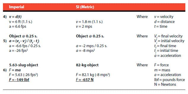
- 1) Tossing a basketball at a door panel 6 ft. (1.8 m) away and the ball is in flight for 1.1 s. It is moving at 6.6 fps (2 mps).
- 2) It weighs 1.3 lb (0.04 slugs/0.6 kg) and is in contact with the door panel for 0.1 s. while the air inside the ball compresses. During the short time the sphere is misshaped, its velocity goes to zero, having a negative acceleration of -66 fps2 (-20 mps2).
- 3) After that, the reverse occurs, the misshapen ball normalizes its shape, the force to become a sphere again pushes the ball away from the door panel, and it rebounds. The force imparted onto the door panel is calculated using the acceleration of the object (basketball) while stopping. Then, the mass of the object (basketball) is added to find an applied force of -2.6 lbf (-12 N).
Calculations from these examples are:

Scaling up this example, let’s again:
- 4) Move a mass with a velocity of 6.6 fps (2 mps) and increase the mass of the object to a human weight. Let’s represent the worst case using a mass that is airborne (like the basketball) as it impacts the door panel and weighs 181 lb. (5.63 slugs/82 kg) with a velocity that goes to zero in 0.25 seconds.
- 5) A human body is not a solid object like a block of metal; it takes time to come to a stop, but it is a little more compressible than a basketball. If a solid-metal object of the same weight were to impact the door, the negative acceleration would be very high, because the time to stop the entire mass is near 0 s. When the metal object’s leading edge hits the door panel, the back edge hits at the same time; there is no compression of the object. During an impact, the skin of a human body is first to contact the door, then the muscles and fat. Then, there is movement of the organs and skeleton, then of the muscles and fat on the other side on the body. That compression of the body is what can take 0.25 s. to bring to a stop (zero velocity). The more rigid an object, the higher the stopping force; the more compressible an object, the lower the force, because of the time-to-stop difference.
- 6) In this example, the force imparted onto the door panel is calculated using the acceleration of the object (human) while stopping, then putting in the mass of the object (human) to find the applied force of -149 lbf (-657 N).
Calculations from these examples are:
A final example is from Football Physics, The Science of the Game[3] with minor decimal and unit corrections for simplicity:
- 7) “The force linebacker Dick Butkus exerts on his opponent is proportional to the ball carrier’s mass times his acceleration: F = ma. Let’s say that Butkus is facing off against a fullback of a similar weight, 245 lb. (7.6 slugs/111 kg). The back hits a hole opened up by his hardworking offensive line, and he’s running hard, so his initial speed is about 10 yd. per s., or 30 fps.
- 8) “Then, Butkus enters the picture, and the play comes to a crashing halt. The back’s final speed, immediately after the hit from Butkus, is zero.”
- 9) “The duration of the hit, from the first contact of pads to the point when the back’s forward motion stops, is about 0.2 s. (We can determine this by analyzing a slow-motion replay of the hit.) Dividing the speed change by the time interval over which it occurred gives us the acceleration of the back, or, rather, the deceleration, as his forward motion is stopped cold: a = (0-30 fps)/0.2 s. = -150 fps2. (The minus sign tells us that a is actually a deceleration.) Now, all we have to do is multiply by the ball carrier’s mass to find the force acting on him: -150 fps2 X 245 lb. (7.61 slugs) = -1,142 lbf (5050 N), or about three-fifths of 1 T. in the backward (negative) direction.”
Calculations from these examples are:
It is clear that the code-required 5,000 N (1,125 lbf) for retainers is nearly the retaining force required to stop a 111-kg (245-lb.) fullback running very fast into the center of a door panel. When you add the code-required door guiding means, the total force is 7,500 N (1,688 lbf) before any appreciable displacement or permanent deformation can occur. These door panels are very strong when maintained with the correct components, mounted with the correct fastenings and undamaged.
To be very clear, these code forces are to the middle of the door panel, so each gib and retainer on the bottom is retaining only its share of the total applied load. If there are two gibs, the bottom of the door panel is responsible for half of the total load of 2,500 N (560 lbf), or 1,250 N (280 lbf), and each gib is responsible for half of that, or 625 N (140 lbf).
In many designs, there is only one bottom door retainer. It has the job to resist a third of 5,000 N (1,125 lbf) all by itself. The 1,500 N (375 lbf) it must resist, without appreciable displacement or permanent deformation, is a very large force. This requirement has kept our doors hazard free when mounted with correct fastenings and replaced when damaged with the same manufacture. We all must be aware that these components prevent the most terrible of accidents from occurring and install and maintain them accordingly.
Code writing utilizes history of incidents and hazard assessment based on predictable human behavior, foreseeable misuse, and common sense when specifying the minimum strength of door panels and other requirements. People and equipment fall against and are pushed against elevator door panels. These incidents can occur to any elevator door panel. Protecting against door failure nearly up to the force of a fullback running full speed at the middle of the door panel is the minimum force against which the door panels must protect from failure, without appreciable permanent displacement or deformation of the entrance components. This appreciable deformation includes the gibs and retainers.
Conclusion
Mechanics should look at all door guiding means (gibs) and ensure all mounting screws are in and secure. They should also look at eccentrics and adjust per manufacturers’ instructions, and look at retainers and ensure all hardware is present and secure.
Elevator companies should ensure they have manufacturers’ instructions for repairing, replacing, adjusting and maintaining door equipment. They should also train employees on the importance of these essential elements and ensure there is adequate time on the job devoted to performing these critical tasks.
Learning-Reinforcement Questions
Use the below learning-reinforcement questions to study for the Continuing Education Assessment Exam available online at www.elevatorbooks.com or on p. 113 of this issue.
♦ Which A17.1 requirement specifies the door components requiring maintenance?
♦ To which temperature are entrances heated during a fire test?
♦ What force does the hose spray apply to heated panels?
♦ What can be changed on the door panels without violating the listing?
♦ What needs to be adjusted to ensure door panel retention?
♦ In which edition of A17.1 were safety retainers first required?
♦ Which requirement of A17.1 specifies the strength requirement for door retainers?
♦ When was labeling of entrances first required?
♦ What has A17.1 Section 8.6 required since 2000?
♦ What is the correct value for the adjustment of up-thrusts (eccentrics)?
References
[1] Griffiths, Jeff. “Hose Stream or Smoke Screen?” Doors and Hardware, February 2008, p. 32-36.
[2] Kroemer et al. National Technical Information Service, U.S. Department of Commerce. “Horizontal Static Forces Exerted by Men Standing in Common Working Positions on Surfaces of Various Tractions Including Coefficients of Friction between Various Floor and Shoe Materials,” AD 720-252, Aerospace Medical Research Laboratory, Wright Patterson Air Force Base, Ohio (January 1971).
[3] Gay, Timothy, PhD. Football Physics: The Science of the Game, Holtzbrinck Publishers (2004).

Figure 2: Typical impact test setup 
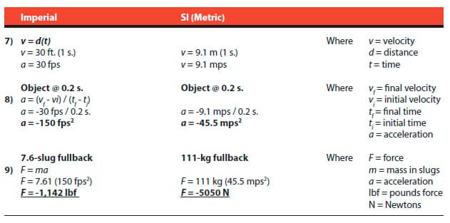
Figure 3: Typical label on the door panel indicating evidence of fire testing 
Figure 4: Hose stream test from UL 10B, NFPA 252 and CAN 4-S104 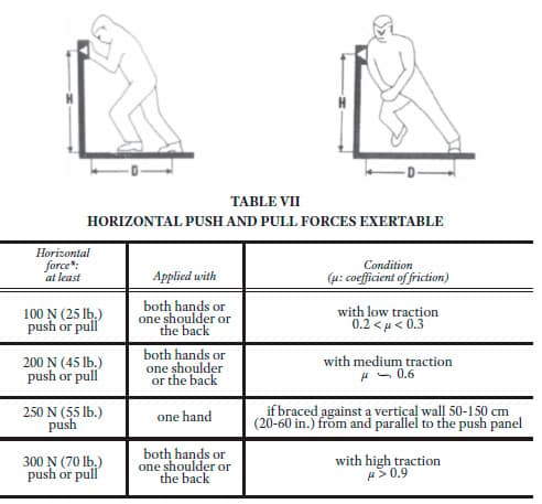
Figure 5: Exertable human push forces[2]

Get more of Elevator World. Sign up for our free e-newsletter.