Elevator Wire Ropes Inspection: Regulations, State of the Art, Statistics
Oct 1, 2024
by Bruno Vusini, Daniel Rossi and Tommaso Bertani
KEY WORDS: Magnetic, rope, monitoring, safety
This paper was presented at Elevcon 2023 in Prague, Czech Republic.
Abstract
The traction cables of lifts play a very important role in the safety of people. In Italy alone, there are about 900,000 working lifts that make an average of more than 1 million trips per day. This means that millions of people rely on the proper operation and maintenance of all components of this particular (and let’s say intrinsically safe) machine. There are, of course, laws and standards that must correctly regulate the maintenance operations that allow the elevator to operate as correctly and safely as possible, and it is often taken for granted that maintenance technicians operate in total accordance with these documents. International standards, such as ISO 4344, require the identification of very small damages that are really difficult to visually identify and, for this reason, a real rope visual inspection takes hours to complete.
Fortunately, technology is advancing and, concerning rope analysis, much more efficient inspection methods have appeared on the market in the last 10 years.
The purpose of this article is to provide basic information about the inspection market, laws and standards and the results obtained over a period of more than 10 years, from which both the advantages of using advanced methods and the total inefficiency of antiquated analysis methods are evident.
1. The Laws and the Regulations
Here the law is imperative: “Ropes and their attachments must be minutely controlled.” This is DPR 162/99, which places the burden of inspection on the maintenance technician, the administrator and the condominium owner. What does this mean? It means that if a problem occurs, the administrator and the condominium owners will eventually have to answer for it, together with the maintainer. One important thing, however, is that the condominium is always responsible for what happens due to poor (or non-existent) maintenance of common property.
A failed inspection of a lift rope is equivalent to a lack of maintenance. How does the tenant realize this? By requesting the minutes of the inspection of something that, after all, is also his.
The law, of course, cannot stipulate how the checks are to be carried out, let alone the rejection criteria. This is taken care of by the regulations, which are very comprehensive in this respect.
In the lift sector, we have UNI ISO 4344 (ISO, 2022) and EN 12385, the latter harmonized, which define on the one hand the rejection criteria, and on the other hand, the contents of the rope’s use and maintenance manual on which the normative reference should always be present. The maintenance technician, but also the building administrator, should always have a clear picture of the situation, also because, beyond safety considerations, ropes in particular are mentioned several times in Presidential Decree 162.
Unfortunately, contrary to what one might think, UNI ISO 4344 is unknown to most people. It often happens that maintainers and notified bodies refer to laws that are now obsolete, such as Presidential Decree 1497 of 1962 or other references that have now been repealed.
For this, and other reasons, UNI decided to produce a technical specification that could provide clarity once and for all.
The document is UNI/TS 11807 (UNI, 2021) published mid-March 2021, after a gestation phase of about five years, during which they tried to understand how to publish a document that could be used as a real guide. We are going to describe, in broad terms, some interesting passages of the standard, in particular the part in which the magneto-inductive method is described and standardized.
2. The Laws and the Regulations: A Closer Look
As mentioned, the technical specification introduces the methodology from its basics. The meaning of technical terms such as “measuring head,” “localized discontinuity,” “magnetic saturation” and many others is then indicated. The aim is obviously to explain in a simple and clear manner what is normally found in a scientific bibliography that is not accessible to everyone.
Table 1 defines the types of deterioration that need to be assessed in wire rope, such as broken wires, wear, etc., alongside the methods of assessment.
Here, visual remains the main one, but magneto-inductive also appears for the first time in history as an option available to the maintainer.
So, is visual inspection always sufficient? A very interesting parenthesis can be opened here.
Let us start by saying that, in the field of non-destructive testing, the visual method is regulated by a standard called ISO 9712. This naturally applies to quality controls and special inspections of parts of various kinds. The visual method is used whenever a visible defect is to be highlighted, i.e., one that does not require special additional investigation techniques. A hole on a plate is a visible defect, as is a cut on a pipe. In the world of ISO 9712, certified technicians are subjected to special visual examinations to ensure that their measuring instrument (their eyes) is up to the task, and they are trained ad hoc to know exactly what to look for.
In the rope sector, the situation is different. The visual method is not a regulated type of examination carried out in a controlled-light environment, and above all, there is no report as to exactly what the technician has done. Here, the concept of “visual” is modified because it often takes on the meaning of “what the technician sees during the test,” which is quite different from “what is external and therefore visible.”
The maximum number of permissible broken threads is reduced to four in certain situations. And seeing four broken wires (wires, not strands) on a rope is very complicated.
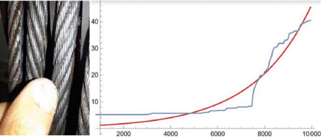
If we add to this the very short timescales (Figure 1) that have to be met for economic reasons and the lack of knowledge of many technicians in the sector, we understand why many installations in operation have ropes that should have been replaced long ago.
So does a rope break with four broken wires? No, the rejection criteria defined by the standard allow a sufficient degree of safety to be maintained so even when I reach the maximum permissible levels, the lift does not collapse. However, the evolution of breaks on a rope is not linear. As the number of broken wires increases, the time it takes to get a new one decreases.
That is why the limits serve precisely to understand when it is time to replace the rope so that the situation does not become completely uncontrollable within a short time.
This is why the chapter on visual inspection in the technical specification is extremely detailed, with guidance on correct lighting, photographs of practical examples and many tables for rejection criteria. Precisely with regard to rejection criteria and the ill-considered habit of concentrating on macro-breaks (for which the rope is immediately rejected, and the installation has to be stopped), among the criteria we have one relating to so-called “valley breaks” or “broken wires at the point of contact between the strands.”
These are very insidious types of breaks, which are extremely difficult to identify and are characterized by having one of the ends of the broken wire not being visible: You only see one wire coming out of the rope without being able to identify the other end.
The danger of such a defect arises from the fact that it could be the mirror of an internal (therefore not visible) situation that is now compromised. When there is such a broken wire on a rope, it must be discarded.
Thus, even a single broken wire can take on a very important significance.
Magneto-inductive testing fits in very well in this context, as it allows the identification of all defects, external and internal, visible or not, and provides the maintainer and the building owner with a graph that proves, firstly, that the inspection has been carried out and, secondly, protects them from problems that may occur later.
Let us imagine that an accident happens due to one of the ropes, and the judiciary starts its course. The last minutes will be requested to make sure that the checks have been done correctly. Let’s imagine that the maintainer’s report says, “Found a few broken wires.”
How many? Where? Why wasn’t it replaced? If they were less than those specified in the regulations, why wasn’t it written down? Let us always remember what weight one carries when signing a report. One takes a picture of an existing situation and admits that the installation continues to function, but this outcome must necessarily be supported by evidence.
A graph, in this situation, solves the problem because it shows exactly the state of wear and tear of the rope and allows you to legitimize your choice. This applies to the maintainer but also to the administrator and the condominium. They have an obligation to protect the common property; we have already said so.
Finally, the minutes. The report must be complete and detailed and must indicate how the test was carried out and what kind of defects were found. The report must be the result of the inspection and must be the way in which the maintainer communicates the outcome. If the rope can be maintained, it must be stated what was found and why replacement can be avoided. Conversely, if the rope is to be replaced, we must know why.
3. The Magneto-Inductive Method
The methodology called MRT (Magnetic Rope Test) is currently used in various sectors, in some of which it is even mandatory.
It uses a relatively simple physical principle, based on measurements of dispersed magnetic fields due to the presence of anomalies on the measurement object. Let us therefore take a look at the basic principles of the method in order to understand how it works (Vusini, 2021; Canova et al., 2008; Canova et al., 2009).
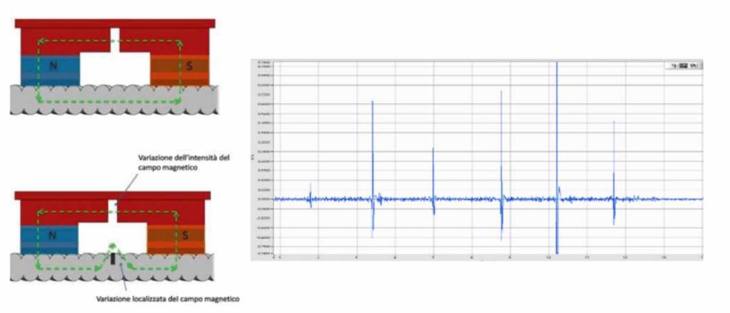
In Figure 2, we observe a simple configuration often used for educational purposes in which a magnetic field is forced by a structure consisting of permanent magnets and grain-oriented iron. The field produced by the permanent magnets is enclosed within the rope, which consists of ferromagnetic material characterized by a suitable magnetic characteristic, which is obviously non-linear.
When the rope does not have any defects, all the magnetic flux flows inside it without any particular dispersion except for that due to the presence of the strands. When defects are present, such as broken strands, a proportion of the magnetic flux will be deflected, as can be seen in Figure 2. This stray flux exits the wire and enters the air above, literally “jumping” the defect.
This gives rise to an effect detectable by appropriate probes placed at specific points in the device, which depends on what the broken wire looks like, its size and its arrangement in the rope. The final result is an easy-to-read graph highlighting the presence of broken wires, wear and distortions — what should be identified when inspecting the rope and which, often, a visual inspection fails to detect.
However, the method also has a second, less “technical” but more “legislative” value. It is the only way we can be sure that the ropes have been checked. Yes, because let us not forget that today we have a report, often minimal, in which the maintainer writes a sentence, sometimes sibylline, about the state of wear of the ropes.
Words such as “rope OK,” “good,” “a few broken wires” are unfortunately the standard and, from the pictures that will be presented later, we may wonder, “But did they really check them? How is it possible that these ropes are still in place?”
Obviously, the ordinary user, and often the administrator, cannot be aware of the condition of the ropes because, for them, they are just one of the technical parts of the system. But let us never forget that when we take the lift, we are all taking a leap of faith in those who have maintained the system.
Although the lift is a very safe system, the safety behind which we sometimes take shelter depends on how the maintenance has been done.
4. Visual Analysis — How It Is Made and How It Should Be
In a lift, we know, there is only one rope to control. On old installations you still find two, but the average in Italy is four ropes. Today there are many lifts without a machine room (so-called machine-room-less or MRL) with six or more ropes. Let us therefore try to understand how the inspection of the ropes should be carried out in order to operate according to regulations.
The maintenance technician should stop the installation, approach the first rope and inspect it around its entire circumference to see if there are any broken wires in that section. If so, he should note the position and number of wires, counted over a reference length defined by the standard.
You can then move on to the next wire, repeating the process. Once the inspection on the first section has been completed, the cabin should be moved to approach the next section, repeating the operation.
It is not possible to perform the inspection with the lift in motion as this would violate the most basic safety rules with the risk of serious injury. Once the inspection is complete, the number of anomalies found in the worst section should be compared with what is indicated in the standard. Only then can a decision be made whether or not to carry out the replacement.
But how long does it take to carry out such an operation?
Assuming that the section of rope that can be inspected by the maintenance technician is half a meter long and that the installation has four stops, at least 30 successive repositionings of the lift are necessary. Let us assume that there are four ropes and that the time taken to visually check that “half meter” is at least 60 s for each rope.
Doing the appropriate calculations gives a total time (excluding the various notes of the defects found) of 48 min. If the installation had eight stops, the time doubles (more than an hour and a half). A document published by an association of lift manufacturers and maintenance companies shows that the average time spent inspecting the entire machine room (ropes, inverter, control panel, motor, pulleys) is between a minimum of 5 min and a maximum of 10 min. Even considering the longer timeframe and assuming that half of the time required for the total inspection (5 min) is spent on the ropes, it is complex to assume that the inspection is carried out as a whole.
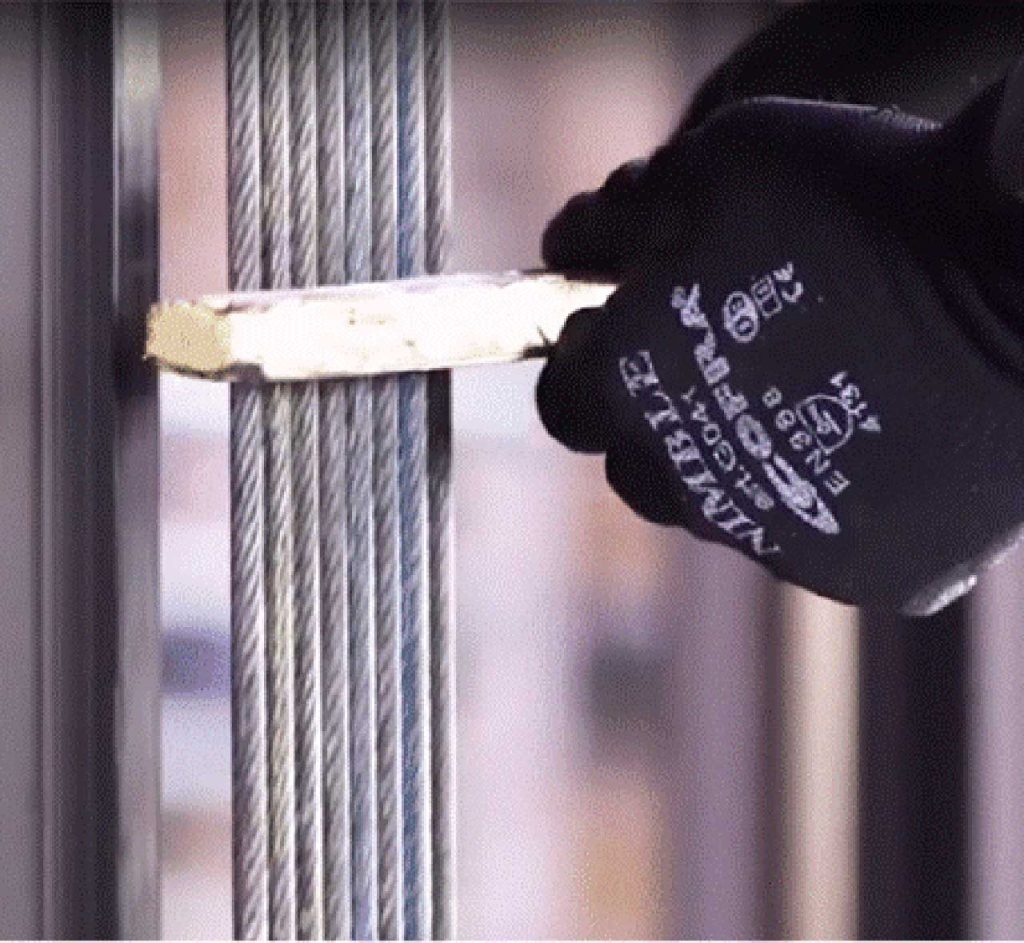
In fact, what has been described above is not normally carried out. The classic inspection that the maintenance technician carries out is the so-called “wood” inspection (Figure 3).
Basically, a piece of wood is placed on all the ropes, and the lift is moved at nominal speed. When the maintainer feels a vibration of the wood, he assumes that it is due to the presence of broken wires on the rope.
Apart from the fact that it makes one smile a little to see the use of such a technique in a context of applying specific regulations in the year 2022, it is also evident that the timber would be borderline sensitive to the presence of “something” at the point of contact with the rope. But anyone who has studied a minimum of geometry knows that a straight line has only one point of contact with a circumference. Here, there would be 360 degrees to inspect.
Finally, it is interesting to add that there is no law or regulation requiring the use of this piece of wood (and I would be surprised if it were the other way around). It is a “technique” that has now become part of the daily routine of many operators in the sector, which is neither regulated nor described.
5. Statistic Analysis 2012-2022
During the last 10 years of activity, magneto-inductive testing has been applied to approximately 70,000 lift systems nationwide. This number is sufficiently high, even though it was obtained on a 10-year basis, and makes it possible to have at one’s disposal a quantity of data that is certainly representative of the overall plant stock, constituting approximately 10% of it.
By analyzing the data, it is possible to observe the condition of the ropes, but also an interesting range of information regarding the age of the installed ropes, their diameters, the average height of the installations and, last but not least, the results of visual examinations carried out during previous inspections. These data, appropriately cross-referenced, give us an overview of the national rope park and also of the veracity of the traditional findings.
It must be said, as a premise, that all the lifts were in operation and, therefore, none of them were in a dangerous condition based on the visual examinations performed in the previous six months.
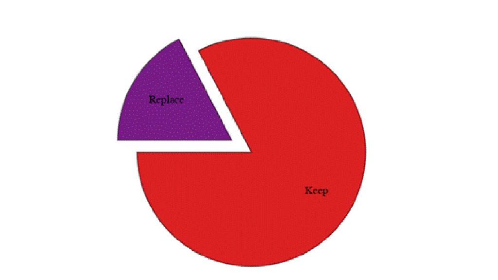
The outcome detected (and analyzed by an expert technician) by the magneto-inductive method provides a three-level discriminator: new ropes, ropes to be kept under observation and ropes to be replaced. In Figure 4, new ropes and ropes to be kept in observation have been merged.
This subdivision makes it possible to immediately see what state the ropes are in and to act accordingly. Through a view of the graph, it is also possible to see where the ropes are damaged, and which of the ropes have problems. In the course of the analysis, as previously explained, the result that the maintenance technician has entered in the appropriate register in the engine room is also recorded. This outcome was the result of the visual analysis previously carried out. Out of the total of more than 70,000 systems observed, it is interesting to see what terminologies are used to indicate the presence (or absence) of defects (Table 1).
| N.R. | 40166 |
| Wearing | 9417 |
| Broken Wires | 4455 |
| Good | 4045 |
| Worn | 2631 |
| Discrete | 2540 |
| Normal Wearing | 1255 |
| Oxide | 1063 |
| ND | 776 |
| Good Status | 723 |
| External Broken Wires | 650 |
| Ok | 583 |
| Good Wire Ropes | 546 |
| N,D | 461 |
| Disc | 408 |
| No Broken Wires | 340 |
| Wearing in Normal Status | 320 |
| Positive | 315 |
| Consumed | 256 |
| N.N. | 236 |
Table 1 displays more than 1,300 different types of outcomes. The most frequent ones are shown here, among which an N.R. (Not Detected) out of about 40,000 installations stands out. Well over 50% of the installations analyzed did not have an outcome related to the state of preservation of the ropes (or at least not reported to us). There are also outcomes that are difficult to understand, such as Disc, Oxide, Broken Wire(how many and where?).
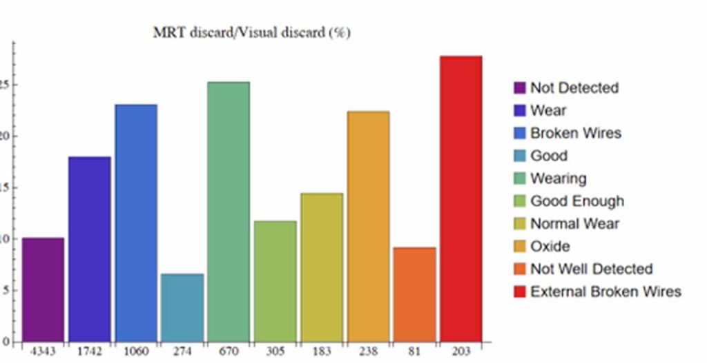
Let us now see, for each of the main outcomes provided by the maintainer, what the actual state of preservation of the traction ropes was (Figure 5).
The graph in Figure 5 is very interesting. It shows that more than 10% of the ropes for which the outcome was not available, some 4,500 lifts, were in need of replacement. This number is impressive considering that 4,500 lifts move a very large number of people. In the case of results corresponding to the outcomes “Wear,” “Broken Wires,” “Oxide,” the percentage approaches, or exceeds, 20%. Almost 15% replacement occurs for the outcome “Normal Wear and Tear.” We note that, even in the case where the ropes are defined as “Good,” there is a margin of error of more than 5%, which corresponds to almost 300 installations.
The total number of non-standard installations is approximately 11,000 lifts, which is a huge number. These installations were in service at the time of the inspection.
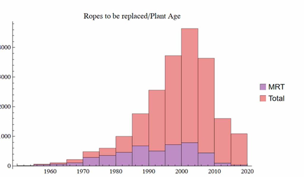
From the data in our possession, it is also possible to observe the distribution according to the age of the ropes. Italy is a country where the fleet of installations is rather old, and this is confirmed by the graph below (Figure 6).
From the instrumental results, it can be seen that, in percentage terms, the discrepancy for older ropes is greater, as can easily be guessed. An older rope should have worked harder and therefore the number of cycles should be higher. Of course, this is not said a priori, but it is statistically correct to assume this to be true.
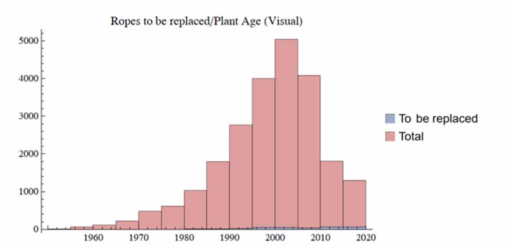
Contrary to the above, the results provided by the maintainers do not show a trend similar to Figure 7, but a number of installations defined as “To be replaced” that is completely unrelated to the age of the ropes themselves. This number is, moreover, extremely limited and not credible.
From the data shown above, there is a tendency to “not give an outcome” in order to (apparently) reduce liability. The use of an objective and documentable methodology, on the other hand, succeeds in providing a more accurate picture of reality.
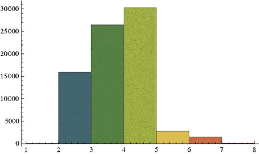
Another interesting piece of data is the number of ropes present on the installations (Figure 8). Here it can be seen that the largest number of lifts still have fewer than four ropes, which further confirms the old age of our installations.
6. Conclusions
Some evidence of big problems in standard visual analysis on elevator ropes has been shown in this paper with a new technology that increases the knowledge around conditions. This technology has been accepted by the main regulations around the world, but it is still only used in some special cases. The real advantages are shown with specific reference to repeatability and to the certainty of the results.
References
[1] Vusini, B. (2021). Lift wire cables maintenance. ANACAM MAGAZINE, 12.
[2] Canova, A., Vusini, B. (2008). Magnetic Analysis of Non Destructive Testing Detectors for Ferromagnetic Ropes, COMPEL, 27(4), 867-878.
[3] Canova, A., Ficili, F., Gruosso, G., Vusini, B. (2009). Device for the monitoring of multicable system. Patent WO2009IB50656 20090218, 18/02/2009.
[4] ISO (2022). ISO 4344:2022 – Steel wire ropes for lifts — Minimum requirements. 01/12/2022.
[5] UNI (2021). UNI TS 11807 – Ascensori, piattaforme elevatrici e montacarichi – Sistemi di sospensione e compensazione dell’impianto e sistemi di attuazione del paracadute a mezzo di funi di materiale ferromagnetico non rivestito. Requisiti per la verifica e criteri di scarto, 18/03/2021-
Get more of Elevator World. Sign up for our free e-newsletter.
