Elevatoring Communications Towers: 1956-1968
Feb 1, 2013
The infrastructure that supports modern communications systems (TV, telephone and radio) has changed dramatically over the past 25 years. Television antennae have vanished from rooftops, satellites and satellite dishes have replaced massive broadcast towers, and the newest incursions on the landscape – cell-phone towers – lack any pretense of engineering or aesthetic quality. The latter structures are also not accessible to the public and often viewed as unwelcome additions to their surrounding environment. (This is, perhaps, especially true of such towers “designed” to look like gigantic, misshapen fir trees.)
In 1950s Europe, however, the desire to build a comprehensive communications network resulted in the construction of a series of remarkable towers specifically designed to be architectural icons and community symbols. These buildings also presented unique elevatoring problems, which included spatial constraints, severe internal environmental conditions and substantial building movement or sway. These challenges will be explored here through the examination of four communications towers completed between 1956 and 1968.
One of the first large-scale communications towers built in Europe was the Stuttgart Fernsehturm (TV tower) in Germany, designed by German engineer Fritz Leonhard (1909-1999) and completed in 1956. From the base of the cylindrical concrete tower to the top of its massive steel-lattice aerial, the structure stands 712 ft. tall. Its principle architectural feature is a cylindrical “pod” that begins 445 ft. above grade. The pod contains four enclosed floors that house mechanical rooms (first floor), kitchens and support spaces (second floor) and a restaurant (third and fourth floors). The pod is also topped by a two-level outdoor observation deck. The decision to incorporate public spaces into the tower meant that passenger elevators were required: in this case, two 16-passenger machines. The primary design challenge was, in essence, how to efficiently place rectangular elevator shafts into a cylindrical volume. The elevators for the Fernsehturm were designed, manufactured and installed by C. Haushahn GmbH & Co. of Stuttgart, Germany. The company, founded in 1889, began building elevators in 1895. In 1922, the firm manufactured and installed elevators in an earlier important Stuttgart tower, the 56-m-tall Bahnhofsturm (train station tower).
The elevators for the Fernsehturm departed from the typical plan configuration of rectangular cars and shafts. One corner of each rectangular car was chamfered, resulting in a five-sided design that fit neatly into the shaft, providing space for counterweights in niches behind the angled walls and a mechanical chase behind the car shafts (Figures 1-3). The elevator plant employed gearless machines that had a maximum speed of 800 fpm. One car served eight landings (the first landing was at 246 ft.), and the other served five landings. Each car was equipped with side emergency-exit doors, which were designed such that they could be aligned with each other to facilitate the safe transfer of passengers between cars should one become disabled. The cars also featured center-opening entrance doors, had interiors built of sheet metal with “Aluminyte fixtures” and were equipped with “fan-lite fixtures” and telephones.
The Donauturm or Danube Tower in Vienna was completed in 1964 and designed by architect Hannes Lintl (1924-2003) and engineer Robert Krapfenbauer (1923-2005). The tower (827 ft. tall) also employed elevators that featured a chamfered side. However, in this case, the angled wall held a set of entry doors. In fact, each car was equipped with two sets of center-opening doors, located opposite each other, which were intended to permit “a swift flow of passengers in and out of the cab.” The published tower plans are too schematic in nature to allow a detailed understanding of how passenger flow actually worked in the tower (Figure 4). However, these drawings, coupled with a photograph of a car with both doors open, reveal that one door set was smaller than the other, which raises questions about the actual ease of traffic movement (Figure 5). An additional detail not legible from the plans is the fact that, while only two shafts are present, three cars were in operation: one shaft featured a double-deck car that simultaneously served the observation deck (located at 494 ft. above grade) and the restaurant (in a two-story cylindrical pod above the observation deck).
The cars were “constructed of hard surfaced plastic bonded upon sheet metal” and equipped with emergency exits, the operation of which was similar to those found in the Stuttgart Fernsehturm:
“In the event of a car stoppage, one car can be brought perfectly abreast of the other by powerful standby magnetos so the two exit-way frames match with only the slightest crack. The unbolting of either emergency door automatically switches off the operating circuit in the rescuing car.”
The cars also featured telephones that allowed the elevator operators to communicate with each other and “with all offices of the tower complex.” The 508-ft.-tall elevator shaft was built as a separate concrete structure inside the tower core. It was composed of two distinct sections: an “E”-shaped, 246-ft.-tall freestanding shaft and an upper “T”-shaped shaft connected to the tower’s outer walls.
The elevators were designed, manufactured and installed by Stefan Sowitsch & Co. KG. The company had been founded by Austrian engineer Stefan Sowitsch (1883-1970) in 1914. Between World War I and World War II, the firm established a relationship with the Swiss firm of Brown, Boveri & Cie (founded in 1891), which specialized in building electric motors. The two Sowitsch gearless machines built for the Donauturm where powered by 70-hp Brown-Boveri motors and featured eight-groove driving sheaves (Figure 6). They were equipped with Ward-Leonard drives “controlled by magnetic amplifiers” to ensure “smooth acceleration and deceleration.” The elevators had a maximum speed of 1,400 fpm, a capacity of 2646 lb. and were fitted with “electro-pneumatic brakes” instead of the typical “solenoid magnetic type.”
The technical description of the Donauturm elevators also outlined the solutions to two problems unique to communications towers: what happens to elevator systems when the tower sways excessively, and what is the impact on elevators operating in an unconditioned space? The former problem was addressed by equipping the elevators with sensors that slowed the car speeds if the tower deviated more than 7 in. “out of plumb” and stopped the cars if the deviation reached 15 in. The solution to the latter problem was described somewhat vaguely but speaks to the challenges of these buildings: “The consequences of winter temperatures turning condensation into ice had to be considered and de-icers were installed on the guide rails.” The cars were also cooled and heated independently.
Ice buildup on guide rails was also a problem confronted in Moscow’s Ostankino Tower. The 537-m-tall tower was completed in 1967 and was designed by a team composed of engineer Nikolai V. Nikitin (1907-1973) and architects Leonid I. Batalov and Dmitry I. Burdin. The interior of the tower’s concrete structural core was open to outside air. In an article in its October 1969 issue, ELEVATOR WORLD reported: “It is estimated that during the time the temperature does not exceed zero degrees Celsius, three to four tons of ice and frost deposit on the rails and shaft walls solely due to the exhalation of passengers.” This necessitated the installation of “ice strippers” on the top and bottom of the car roller guides and top and bottom of the counterweight frame. The car-door suspension tracks were also equipped with “heating devices” to prevent ice from forming and impacting door operation.
When it opened, Ostankino Tower employed four elevators. Its three passenger elevators were laid out in a conventional manner with rectangular cars and counterweights running behind the cars (Figure 7). The fourth machine – a combination freight and service elevator for the three restaurants (which began at a height of 337 m) – employed a five-sided car design similar to the Stuttgart Fernsehturm elevators. The Ostankino elevators were designed and installed by R. Stahl of Stuttgart. This company had been founded by Rafael Stahl (1845-1899) in 1876 and initially specialized in building machines for the textile industry. As the business grew, it gradually increased its production scope and began building elevators in the early 1890s. (The company built its first elevator in 1893.) The Ostankino elevators were described as “gearless machines of the Ward [Leonard] system.” The passenger elevators had a maximum speed of 420 mpm, and the service elevator’s maximum speed was 240 mpm. The units’ length of travel was 384 m, and the passenger elevators served four observation decks (the first located at 147 m) and the upper-level restaurants.
The guide rails were described as having been designed for “a theoretically endless shaft.” This referred to design features that addressed fluctuations in elongation caused by temperature variations. The guide rails were “suspended by their upper ends,” and they moved up and down in “rail brackets by means of guide shoes.” Concerns about excessive tower sway were expressed with regard to its impact on the hoisting and counterweight ropes. This factor, coupled with the uneven heating of the tower’s exterior during the day, meant the ropes “had to be protected against damage. . . caused by hitting the walls.” The solution was to install “impregnated wooden deflectors,” which eliminated the prospect of the ropes striking the concrete walls.
One of the most interesting features of the Ostankino Tower elevators was the absence of car-operating cables. Each elevator communicated with its controller via a radio transmitter and a system of aerials placed on top of the car. This system conveyed all car commands and safety signals, as well as operator telephone calls. Power for the radio was supplied by batteries under the car floor. The batteries also powered the car’s electric heating system. When the tower was closed, the cars were parked at the bottom of the shaft, where the batteries were recharged “by contact lines in the pits.”
The complexities of elevatoring communications towers were further revealed in the design of the Ostankino Tower’s penthouse (Figure 8). Due to the narrow diameter of the upper tower core, the machine room was dispersed across five separate floors: the governors were located on the first floor, the elevator machines were located on the second and third floors, and the control room was located on the fifth floor. (The fourth floor was left open and apparently used for machine maintenance.)
The final tower examined for this study is the Hamburg Fernsehturm, also known as the Heinrich-Hertz-Turm. The tower was designed by architect Fritz Trautwein (1911-1993) and engineer Fritz Leonhard, and completed in 1968. Its three elevators were designed and installed by C. Haushahn. While a plan has survived, only limited information on the elevators, which had a maximum speed of 1,200 fpm, has been published. However, the plan permits a detailed examination of the shaft and car configuration, which reveals that Leonhard (lead designer of the Stuttgart Fernsehturm) had learned from his earlier experiences. The plan consists of a compact central elevator core that includes shafts for two passenger elevators and one freight elevator (Figure 9). The passenger cars featured two-panel side-opening doors and side emergency-exit doors, and had two chamfered corners corresponding to the placement of the corner guiderails. The counterweights were located off center behind the cars. The freight elevator had a rectangular car with two sets of two-panel side-opening doors located opposite each other. This arrangement implies the shaft extended above the passenger shafts and that the freight elevator may have been used to access the elevator machine room. (Unfortunately, no section drawing to confirm this was found.)
This brief survey of communications towers serves as a reminder of the challenges of elevatoring unique structures and of the important role vertical transportation has played in the public success of these remarkable buildings. Each of these towers is still a vital part of their respective communities, and EW readers are encouraged to visit them and share information about their construction and current elevator systems. A future History article will look back at other unique elevator systems covered by EW over the past 60 years.
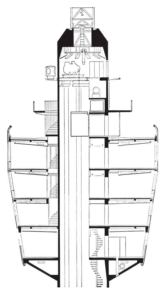
Figure 2: Stuttgart Fernsehturm “Pod” section 
Figure 3: Stuttgart Fernsehturm tower section 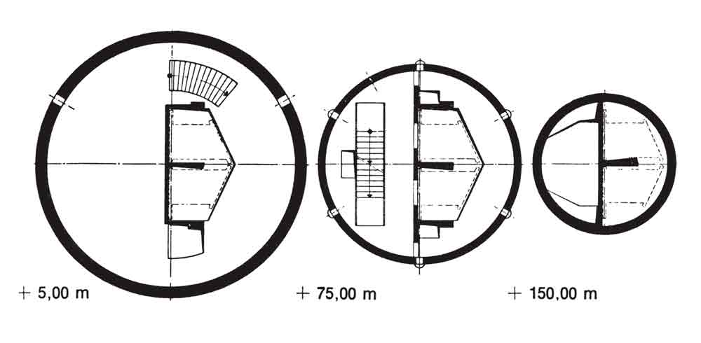
Figure 4: Vienna Donauturm plans 
Figure 5: Donauturm passenger elevator 
Figure 6: Stefan Sowitsch & Co. gearless machine, Donauturm 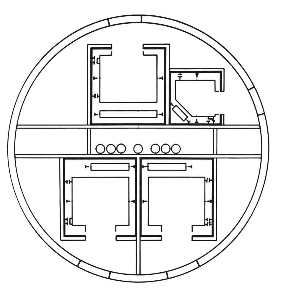
Figure 7: Ostankino Tower plan 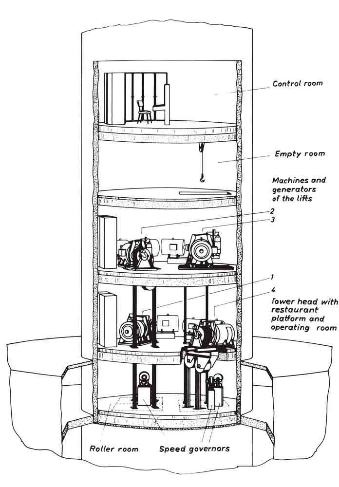
Figure 8: Ostankino Tower penthouse section 
Figure 9: Hamburg Heinrich-Hertz-Turm plan
Get more of Elevator World. Sign up for our free e-newsletter.


