Elevators for Fire Service Access and Occupant Evacuation
Nov 1, 2014

This paper was presented at  Paris 2014, the International Congress on Vertical Transportation Technologies, and first published in IAEE book Elevator Technology 20, edited by A. Lustig. It is a reprint with permission from the International Association of Elevator Engineers
  (website: www.elevcon.com). This paper is an exact reprint and has not been edited by ELEVATOR WORLD.
Abstract
Providing safe elevators during emergencies must include changes in building, fire and elevator codes, as well as modified occupant behavior and increased user awareness. With more knowledge about the dispersal of people using standard means-of-egress, it has become clear to building design professionals that elevators are a key component of any emergency response. This paper presents an overview of the design requirements currently introduced in the United States for fire service access and for occupant evacuation in tall buildings. The new guidelines are intended to reduce access and egress times during emergencies, and they outline a more structured evacuation model.
1. Introduction
Responders must have safe, reliable and unobstructed access to upper floors when handling emergency situations, while building occupants must be able to evacuate safely, orderly and rapidly. Thus, two critical objectives must be met simultaneously — the first, containment and prevention of additional damage to structures; the second, protected evacuation of affected areas.
Until as recently as 2013, the design criteria for fire recall, Manual Phase I Operation under ASME A17.1, has merely required that elevators be taken out of service and recalled to a designated or alternate landing.
Phase I Recall Operations are initiated when smoke is detected in any elevator lobby, machine room or hoistway. Signs are posted at each landing, near the call station, clearly instructing occupants, “In case of fire do not use elevators, use stairs.”
Once elevators travel non-stop to the designated level and Phase I Recall is completed, power-operated doors open and remain open, waiting for emergency responders to decide — based upon the level of incident — whether to use any elevator during Phase II, or to use the stairs.
Phase II is implemented when firefighters determine they need elevators for their use; it becomes operational when firefighters use a key switch in the car-operating panel that is accessible to them. Phase II overrides any building security system so that access to all floors is unrestricted.
During Phase II operations, car doors are under control of the emergency responders by means of a continuous-pressure door open button. To provide more information to emergency responders, if smoke is detected in the elevator machine room or hoistway, a flashing light in the elevator cab alerts the emergency responder to use caution when utilizing affected elevators.
If it is determined that the incident is minor in nature, the elevator system can be returned to normal operation by selecting the bypass position at the main hall station, located at the designated level; further investigation and resetting at the fire command center occurs later.
These two systems are basic in principle and rely on emergency responders to plan and execute a building evacuation by restricting the use of elevators to trained emergency personnel. Concurrently, the only option for tenants is to use stairs for evacuation purposes, allowing emergency responders to assist the disabled and, at the same time, deploy resources and personnel to contain further building damage.
In conceptualizing the use of elevators for occupant self-evacuation, it is essential to remember that both critical objectives – containment/prevention and protected evacuation — can only be achieved through a combination of factors: implementing revised building and elevator codes, ensuring equipment reliability, changing fire department Standard Operating Procedures, increasing human awareness, training, and clear communication.
Changes in Building and Fire Codes were initiated in 2009, based on recommendations from NIST (National Institute of Standards and Technology). Elevator code changes followed later, in the 2013 edition of ASME A17.1.
Before venturing into an examination of high-rise buildings and sophisticated elevator emergency systems, it is essential to look at the evolution of different elevator requirements incorporated by building design professionals when they are developing a project, and the order of magnitude of design strategies for building models.
2. Buildings under 75 Feet (22.8 Meters)
2.1 Elevator Cab Standard Dimensions for New Installations
Must be in conformance with accessibility requirements for elevators classified for passenger use; operation must be automatic. Table 1 shows typical configurations; configurations providing wheelchair-turning space with closed door are possible.
2.2 Existing Elevator Cab Minimum Dimensions in Building Alterations
If existing building conditions will not allow the new cab standard dimensions shown in Table 1, above, elevator car configurations that provide a clear floor area of 16 square feet (1.5 m2) minimum, and an inside clear depth of 54 inches (1370 mm) minimum and clear width of 36 inches (915 mm) minimum, may be permitted.
2.3 Firefighters’ Emergency Operation
Firefighters’ Emergency Operation (FEO) is also known as Firefighters’ Service; it is required for all automatic elevators, except where travel does not exceed 80 inches (2000 mm) and the hoistway does not penetrate a floor. FEO has been standardized over the years to eliminate differences between elevator manufacturers; this allows firefighters to follow standard procedures for any type or make of elevator and eliminate confusion during an emergency.
Phase I Emergency Recall Operation is the automatic fire alarm initiating device, or the manual key-operated return of elevators to the designated level.
Phase II Emergency In-Car operation refers to provisions allowing emergency personnel to operate the elevator from within the car.
2.4 Pit Sump Pump or Drain
If FEO applies, a drain or sump pump with a capacity of 3,000 gallons/hour (11.4 m3/hour) per elevator is required.
2.5 Flood-Prone Areas, FEMA
Federal Emergency Management Agency (FEMA), National Flood Insurance Program (NFIP), Title 44 Code of Federal Regulations (CFR), Section 60.3(a), requires the installation of a detection system with one or more float switches in the elevator shaft to prevent the cab from descending into flood waters. Firefighters’ designated and alternate landings will be above base flood elevation.
2.6 Fire Department Emergency Access
Section 3002.4 of the 2012 International Building Code (IBC-2012) requires at least one elevator for fire department emergency access to all floors in buildings of four or more stories. The elevator must be of such size and arrangement to accommodate an ambulance stretcher 24 inches by 84 inches (610 mm by 2134 mm), with no less than five-inch (127 mm) radius corners, in the horizontal, open position. Standard configuration requires a minimum of 3500 pounds (1,588 kg) capacity. This elevator will be identified by the international symbol for emergency medical services (Star of Life).
2.7 Elevator Lobby
Pursuant to IBC–2012, Section 713.14, an enclosed elevator lobby is provided at each floor where an elevator shaft enclosure connects more than three stories. The lobby enclosure separates elevator openings on each floor by fire partitions and has at least one means of egress. Exceptions are made for: exit discharge levels, unenclosed elevator hoistways, elevator doors protected by a smoke and draft control assembly, installation of an appropriate automatic sprinkler system, pressurization of the elevator hoistway, and elevators serving an open parking garage.
3. High-Rise Buildings over 75 Feet (22.8 Meters)
IBC-2012 defines a high-rise as a building with an occupied floor more than 75 feet (22.8 m) above the lowest level of fire department vehicle access. In addition to the design criteria described in Section 2, above, the following are also required:
Fire Command Center. Displays in Center must provide information that includes: number of elevator banks; elevator bank designation; elevator car numbers and floors they serve; location of elevator machine rooms, sky lobby, and freight elevator banks; standby power loads for all elevators; and emergency power loads for elevator car lighting.
Emergency Voice/Alarm Communication Systems. The operation of any automatic fire detector, sprinkler waterflow device, or manual fire alarm box automatically sounds an alert tone; tone is followed by voice instructions giving approved information and directions for a general or staged evacuation, in accordance with the building’s fire safety and evacuation plans. These systems operate on the alarming floor, floor above and floor below. Speakers are provided throughout the building by paging zones. At a minimum, paging zones are located at: 1) elevator groups; 2) exit stairways; 3) each floor; and 4) areas of refuge.
Emergency or Standby Power Systems. Elevators are normally connected to legally-required standby power systems – not emergency power systems – except for cab lights and communications. Upon loss of normal power, the legally-required standby power system must supply power within 60 seconds. Wiring for legally-required standby power systems can be installed in the same raceway, cables, or boxes used for other general wiring.
Where the standby power source is not of sufficient capacity to operate all elevators to the designated landing at least one elevator in each group will automatically remain operable using the standby power source; others can be selected by manual override with a key switch at a designated level.
Standby power also provides venting or cooling of elevator machine rooms, shunt trip operation, sump pumps, hoistway/lobby pressurization, FEMA flood switch operation.
4. High-Rise Buildings over 120 Feet (36.5 Meters): Fire Service Access Elevator (FSA)
High-Rise Buildings with an occupied floor more than 120 feet (36.5m) above the lowest level of fire department vehicle must comply with Section 3007 IBC-2012. These high-rises are required to have no fewer than two fire service access elevators, or all elevators must be so designated, whichever is less. Each fire service access elevator must have a capacity of not less than 3500 pounds (1588 kg); the net clear cab inside dimensions will be not less than 38 feet2 (3.53 m2). Every floor of the building is served by fire service access elevators. The following features must be added specifically to meet the fire service access elevators:
Phase I Emergency Recall Operation. Actuation of any building fire alarm-initiating device initiates Phase I emergency recall operation on all fire service access elevators. All other elevators remain in normal service, unless Phase I emergency recall operation is manually initiated by a separate, required three-position, key-operated “Fire Recall” switch, or it is automatically initiated by activation of smoke detectors in the associated elevator lobby, hoistway or elevator machine room.
Automatic Sprinkler System. The building is equipped throughout with an automatic sprinkler system. Automatic sprinklers are eliminated in elevator machine rooms, elevator machine spaces, and elevator hoistways. The sprinkler system has a sprinkler control valve supervisory switch and water flow initiating device provided for each floor monitored by the building’s fire alarm system.
Water Protection. An approved method to prevent water from infiltrating into the hoistway enclosure when the automatic sprinkler system is activated is provided.
Shunt Trip. Means for elevator shutdown are not installed on elevator systems used for fire service access elevators.
Hoistway Enclosures. The fire service access elevator hoistway has a minimum two-hour fire-resistance rating on the shaft enclosure that meets building code-required structural integrity. Under FEO, the hoistway height must be illuminated at not less than one foot-candle (11 lux), measured from the top of the car.
Elevator Lobby. The elevator lobby is a transitional element between the fire service access elevator and the remainder of the floor. It is used as a staging area for evacuation or to fight the origin of the fire. The lobby has direct access to an interior exit stairway, allowing safe access to and from any other floor. Lobbies and hoistways are jointly pressurized to eliminate smoke intrusion by establishing pressure differential. The adjacent exit stair enclosure is pressurized separately.
Lobby Enclosure. The elevator lobby is enclosed with a smoke barrier having a fire-resistance rating of not less than one hour; an exception is that lobby doorways can have a ¾-hour fire door assembly complying with smoke and draft control requirements. Enclosed lobbies are not required at exit discharge levels. Each enclosed lobby cannot be less than 150 feet2 (14 m2) in area, with a minimum dimension of eight feet (2440 mm).
Standpipe Hose Connection. A Class I standpipe hose connection is provided in the interior exit stairway and the ramp having direct access from the fire service access elevator lobby.
Fire Service Access Elevator Symbol. A pictorial symbol of a standardized design is installed on each side of the hoistway door frame designating fire service access elevators, at right angles to the fire service access elevator lobby. The fire service access elevator symbol is designed as shown in Figure 2; it will measure not less than three inches (76 mm) in height. The vertical center of the symbol is centered on the hoistway door frame. Each symbol is installed at not less than 78 inches (1981 mm), and not more than 84 inches (2134 mm) above the finished floor at the threshold.
Elevator System Monitoring. The fire service access elevator is continuously monitored at the fire command center by a standard emergency service interface system meeting the requirements of NFPA 72.
Electrical Power. Each fire service access elevator is supplied by both normal power and Type 60/Class 2/Level 1 standby power; including: elevator equipment, elevator hoistway lighting, elevator machine room ventilation/cooling equipment, hoistway/lobby pressurization and any elevator controller cooling equipment.
Protection of Wiring or Cables. Wires or cables that are located outside of the elevator hoistway and machine room and that provide normal or standby power, control signals, communication with the car, lighting, heating, air conditioning, ventilation and fire-detecting systems, are protected by construction having a fire-resistance rating of not less than two hours, or use circuit integrity cable having a fire-resistance rating of not less than two hours.
5. High-Rise Buildings over 120 Feet (36.5 Meters): Occupant Evacuation Elevators (OEE)
All passenger elevators for general public use in a building designed for occupant self-evacuation by elevators must meet the same design criteria and be in compliance with the special provisions required by Section 3008, IBC-2012. While the voluntary incorporation of OEE provides new tools for the architect or design professional to consider when designing tall buildings, under no condition is the installation of such elevators compulsory.
5.1 Additional Exit Stairway
An additional exit stairway is not required for buildings more than 420 feet (128 m) in height, with the exception of those that are designated R-2 (permanent residents).
5.2 Fire Safety and Evacuation Plan
The building must have an approved fire safety and evacuation plan in accordance with the applicable requirements of the International Fire Code. The fire safety and evacuation plan must incorporate specific procedures for the occupants using evacuation elevators.
5.3 Phase I Emergency Recall Operation
An independent, three-position, key-operated “Fire Recall” switch complying with ASME A17.1/CSA B44 is provided at a designated level. OEE are to be used for occupant self-evacuation only in the normal elevator operating mode prior to Phase I Emergency Recall Operation, in accordance with ASME A17.1/CSA B44 and the building’s fire safety and evacuation plan. Occupant evacuation operation is activated with the automatic sprinkler system, smoke detectors, and other approved manual controls.
5.4 Automatic Sprinkler System
The building is protected throughout by an approved, electrically-supervised automatic sprinkler system. Automatic sprinklers are not installed in elevator machine rooms and elevator machine spaces for OEE. The sprinkler system is designed with a sprinkler control valve supervisory switch and a water flow-initiating device, provided for each floor and monitored by the building’s fire alarm system.
5.5 Water Protection
An approved method is required to prevent water from infiltrating into the hoistway enclosure when the automatic sprinkler system is activated.
5.6 Shunt Trip
Means for elevator shutdown are not installed on elevator systems used for OEE.
5.7 Hoistway Enclosure Protection
OEE hoistways are located in shaft enclosures, in compliance with Section 713 of IBC-2012; they must have the required structural integrity dictated by the building’s height.
5.8 Elevator Lobby
The OEE open into an elevator lobby that must have direct access to an interior exit stairway or ramp and be enclosed with a smoke barrier having a fire-resistance rating of not less than one hour. Enclosed elevator lobbies are not required at exit discharge levels. Other than the door to the hoistway, each doorway to an OEE lobby is provided with a 3/4-hour fire door assembly. The fire door assembly complies with smoke and draft control assembly requirements, with a UL 1784 test conducted without the artificial bottom seal. A vision panel is installed in each fire door assembly protecting the lobby doorway. The vision panel consists of fire protection-rated glazing and is located to furnish clear vision of the elevator lobby.
Each fire door assembly protecting the lobby doorway automatically closes upon receipt of any fire alarm signal from the emergency voice/alarm communication system that serves the building. Lobbies and hoistways are jointly pressurized to eliminate smoke intrusion by establishing pressure differential. Any adjacent exit stair enclosure is pressurized separately.
Each OEE lobby has a minimum floor area that will accommodate, at three feet2 (0.28 m2) per person, not less than 25 percent of the occupant load of the floor area served by the lobby. It will be capable of accommodating one wheelchair space of 30 inches by 48 inches (760 mm by 1220 mm) for each 50 persons, or portion thereof, of the occupant load of the floor area served by the lobby. The minimum floor area size for lobbies serving multiple banks of elevators is approved on an individual basis and consistent with the building’s fire safety and evacuation plan.
5.9 Signage
An approved sign indicating elevators are suitable for occupant self-evacuation is posted on all floors, adjacent to each elevator call station serving OEE.
5.10 Lobby Status Indicator
Each OEE lobby is equipped with a status indicator arranged to display all of the following information:
An illuminated green light and the message, “Elevators available for occupant evacuation”, when the elevators are operating in normal service and the fire alarm system is indicating an alarm in the building.
An illuminated red light and the message, “Elevators out of service, use exit stairs”, when the elevators are in Phase I Emergency Recall Operation.
No illuminated light or message when the elevators are operating in normal service.
5.11 Two-Way Communication System
A two-way communication system is provided in each OEE lobby for the purpose of initiating communication with the fire command center or an alternate location approved by the fire department. The two-way communication system includes audible and visible signals and is designed and installed in accordance with the requirements in ICC A117.1. Instructions for the use of the two-way communication system along with the location of the station are permanently located adjacent to each station. Signage complies with the ICC A117.1 requirements for visual characters.
5.12 Elevator System Monitoring
The OEE are continuously monitored at the Fire Command Center or a central control point approved by the fire department. Monitors display elevator floor location; direction of travel and occupancy status of each elevator car; status of normal power to the elevator equipment, elevator controller cooling equipment, and elevator machine room ventilation and cooling equipment; status of standby or emergency power system providing backup power to the elevator equipment, elevator controller cooling equipment, and elevator machine room ventilation and cooling equipment; and notification of the activation of any fire alarm-initiating device in any elevator lobby, elevator machine room, machine space or elevator hoistway.
5.13 Elevator Recall
The Fire Command Center, or an alternate location approved by the fire department, is provided with the means to manually initiate a Phase I Emergency Recall in accordance with ASME A17.1/CSA B44.
5.14 Electrical Power
Normal power and Type 60/Class 2/Level 1 standby power are required to supply elevator equipment, elevator machine room ventilation/cooling equipment, hoistway/lobby pressurization and elevator controller cooling equipment.
5.15 Protection of Wiring or Cables
Wires or cables located outside the elevator hoistway and machine room provide normal or standby power, control signals, communication with the car, lighting, heating, air conditioning, ventilation and fire-detecting systems; they are protected by construction having a fire-resistance rating of not less than two hours, or designed with circuit integrity cable having a fire-resistance rating of not less than two hours.
5.16 Emergency Voice/Alarm Communication System
For OEE, operation of any fire alarm initiating device (smoke detector, sprinkler water flow device, manual fire alarm box) requires that an alert tone be followed by appropriate voice instruction. The alert tone and voice instruction must be provided on the alarm floor as well as the floors directly above and below, and/or selectively to paging zones for elevator groups, exit stairways, each floor, areas of refuge.
5.17 Hazardous Material Areas
No building areas will contain hazardous materials exceeding the maximum allowable quantities per control area, as addressed in Section 414.2 of the IBC.
6. Summary
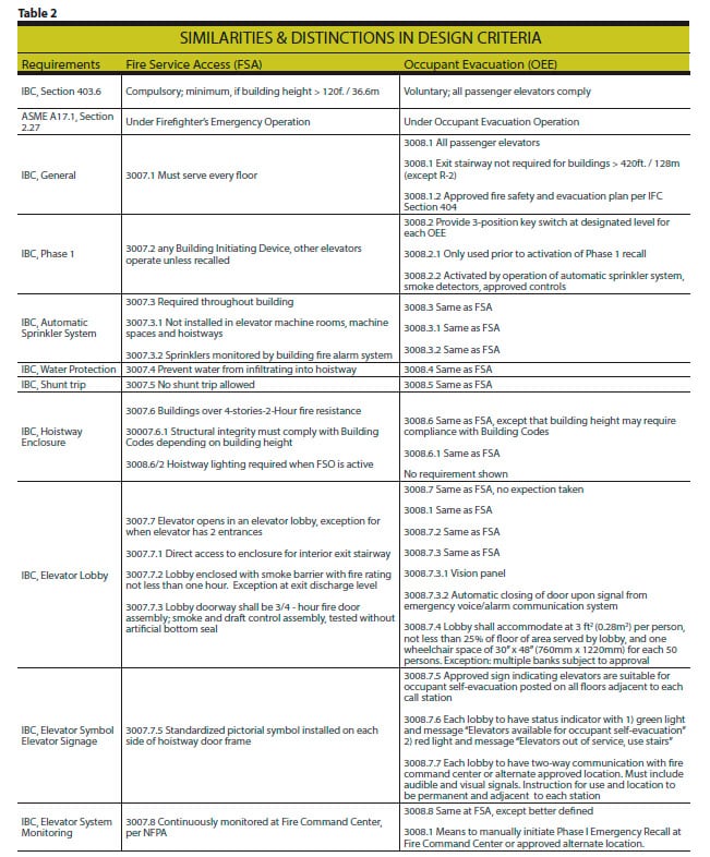
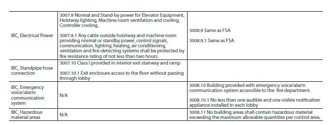
Table 2 summarizes similarities and distinctions in the design criteria of FSA and OEE.
7. Conclusion
With the introduction and incorporation of elevator evacuation systems in building design criteria, elevator operations have become an interactive tool to assist building occupants in their decision-making process during emergency situations. This paper summarizes divergent elevator requirements in relationship to building occupancy and height and provides an overview of code requirements, culminating with the occupant evacuation elevator. It also explains similarities and differences between the A17.1 definitions of Firefighter’s Emergency Operations and Occupant Evacuation Operation in view of discrepancies between Building Codes and Elevator Codes on this subject. Citing one example, Section 3007 of IBC-2013 clearly mandates Fire Service Access Elevators for buildings with heights exceeding 120 ft. (36.5m); ASME A17.1-2013 covers “Firefighter’s Emergency Operation” without that distinction. This discrepancy and other differences must be clarified between Elevator, Building and Fire Codes. Occupant Evacuation Elevators and Fire Service Access Elevators are important building components the design professional must consider when engineering proper and safe means of egress during incidents requiring rescue operations or building evacuations.
References
International Code Council, Inc. (2011). 2012 International Building Code (4th printing, July 2013). Country Club Hills, IL: Author.
National Fire Protection Association. (2013). NFPA 70 National Electrical Code 2014 Edition. Quincy, MA: Author.
Richardson, L. F. & Roux, R. J. (2012). National Fire Alarm and Signaling Code Handbook (7th ed.). Quincy, MA: National Fire Protection Association.
Safety Code for Elevators and Escalators. New York, NY: Author.
The American Society of Mechanical Engineers (2013). ASME A17.1-2013/CSA B44-13
Get more of Elevator World. Sign up for our free e-newsletter.
